RAK5205 WisTrio LPWAN Tracker Quick Start Guide
Prerequisites
Before going through each and every step in the installation guide of the RAK5205 WisTrio LPWAN Tracker, make sure to prepare the necessary items listed below:
- RAK5205 WisTrio LPWAN Tracker
- Micro USB Cable
- Gateway in Range for Testing
- Windows PC
Package Inclusions
- 1pc - RAK5205 WisTrio LPWAN Tracker
- 1pc - Micro USB Cable
- 1pc - LoRa Antenna
- 1pc - GPS Antenna
- 1pc - Battery connector cable (JST) - requires soldering
- 5pcs - Jumper Caps
- Male to Female Jumper Wires
Product Configuration
Interfacing with the RAK5205 WisTrio LPWAN Tracker
To interface with the RAK5205 WisTrio LPWAN Tracker with your Windows PC, you need to download the RAK Serial Port Tool.
Before powering the RAK5205, you should install the LoRa and GPS antenna first. Not doing so might damage the board.
Use Figure 1 as a reference to connect the antennas.
- Connect your RAK5205 WisTrio LPWAN Tracker to your Windows PC using the provided micro-usb cable.
- Open the RAK Serial Port Tool.
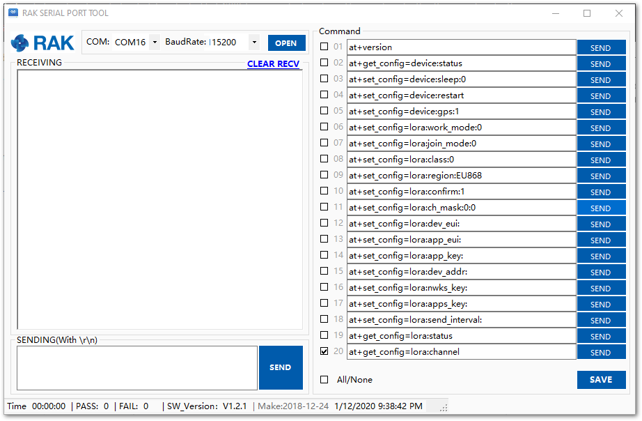 Figure 1: RAK Serial Port Tool
- To setup the correct COM Port number for your device, go to Device Manager by pressing Windows + R and type devmgmt.msc. Or, search for devmgmt.msc in the Start Menu.
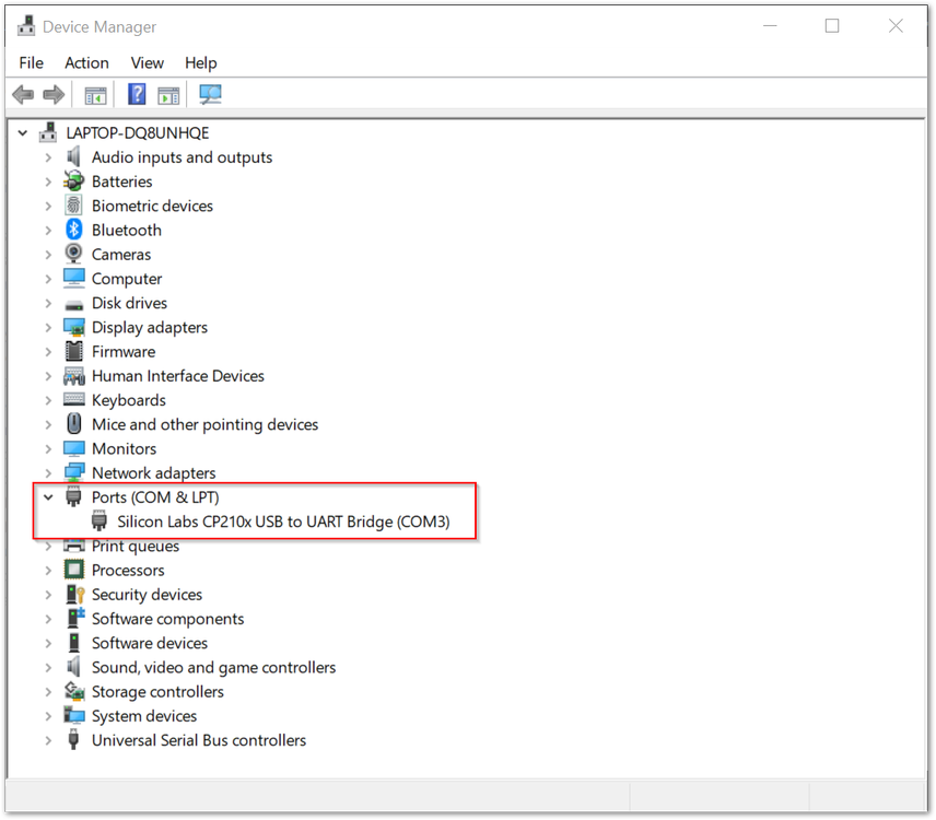 Figure 1: Device Manager
- Look for ports (COM & LPT) and find the name Silicon Labs CP210X USB to UART Bridge and take note of the COM Port Number.
If you can't find any port with the name Silicon Labs CP210X, make sure you have installed the CP210X Drivers on your Windows PC.
- Choose the correct port number and baud rate from the device manager, then click Open.
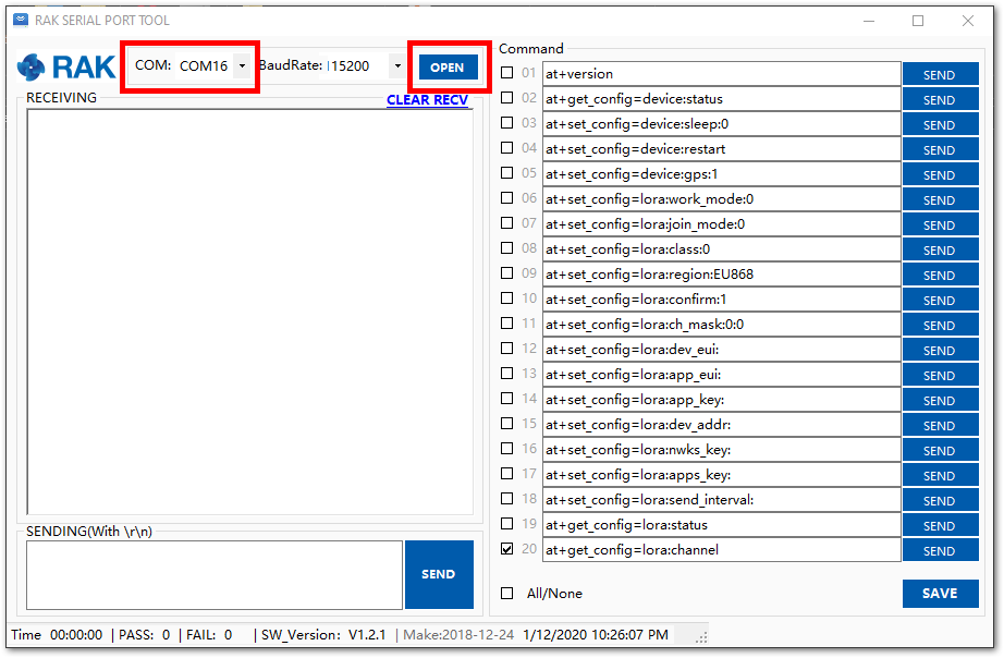 Figure 1: Correct COM Port and Baudrate
Connecting to The Things Network (TTN)
In this section, you will be connecting the RAK5205 WisTrio LPWAN Tracker to The Things Network (TTN). If you don't have an account yet, head on to TTN website and create one. Once done, log in to your account and go to the console.
 Figure 1: The Things Network Home Page
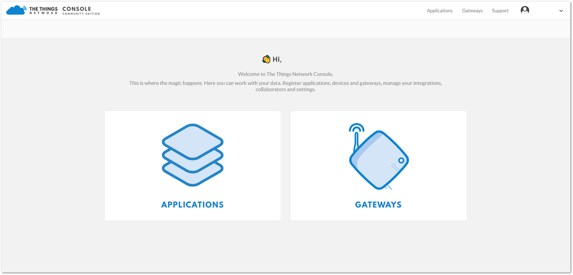 Figure 1: TTN Console Page
- Choose "APPLICATIONS".
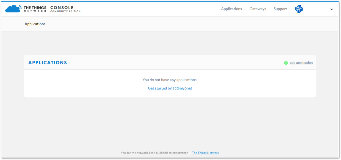 Figure 1: Application Page
Adding An Application
- Click the "add application" button.
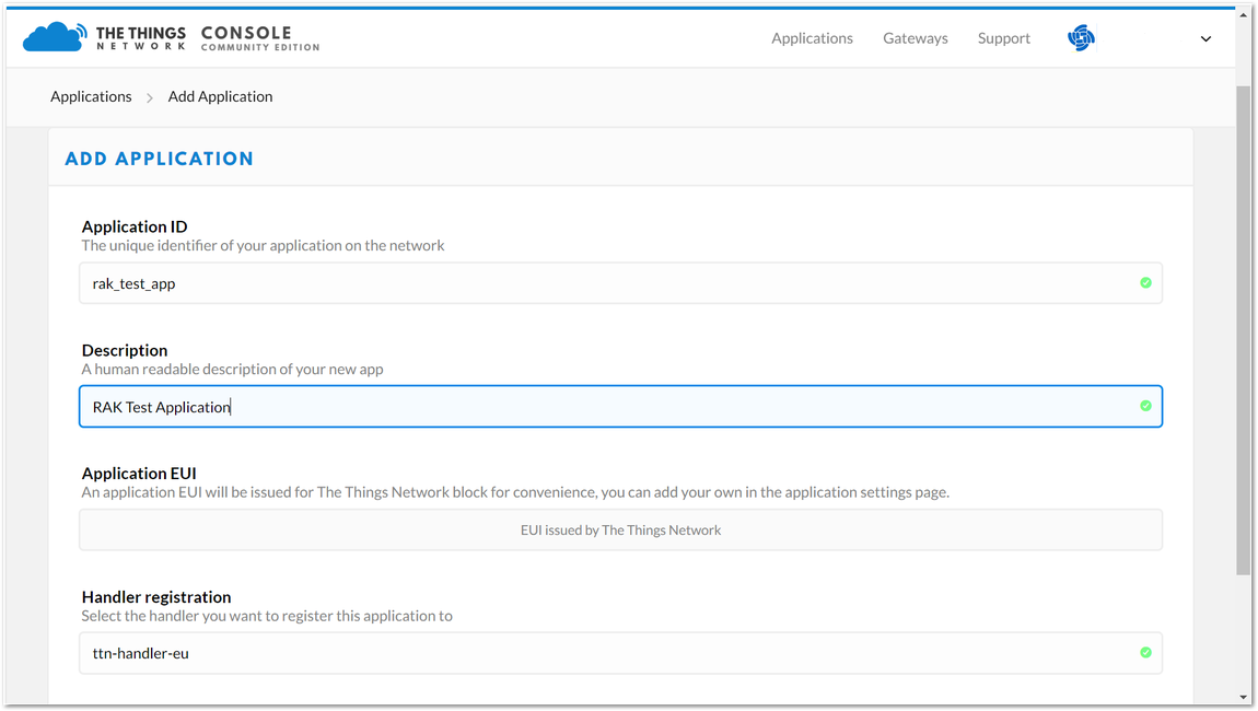 Figure 1: Adding an Application
Here are the things that you should take note of in adding an application:
- Application ID - this will be the unique id of your application in the Network. Note that characters should be in lower case, and no spaces are allowed.
- Description - this is a short and concise human readable description of your application.
- Application EUI - this will be generated automatically by The Things Network for convenience.
- Handler Registration - handler you want to register this application to.
- After you fill in the necessary information, press the "Add application" button at the bottom of the page. If you see the same page as Figure 9, then this means that you have successfully registered your application.
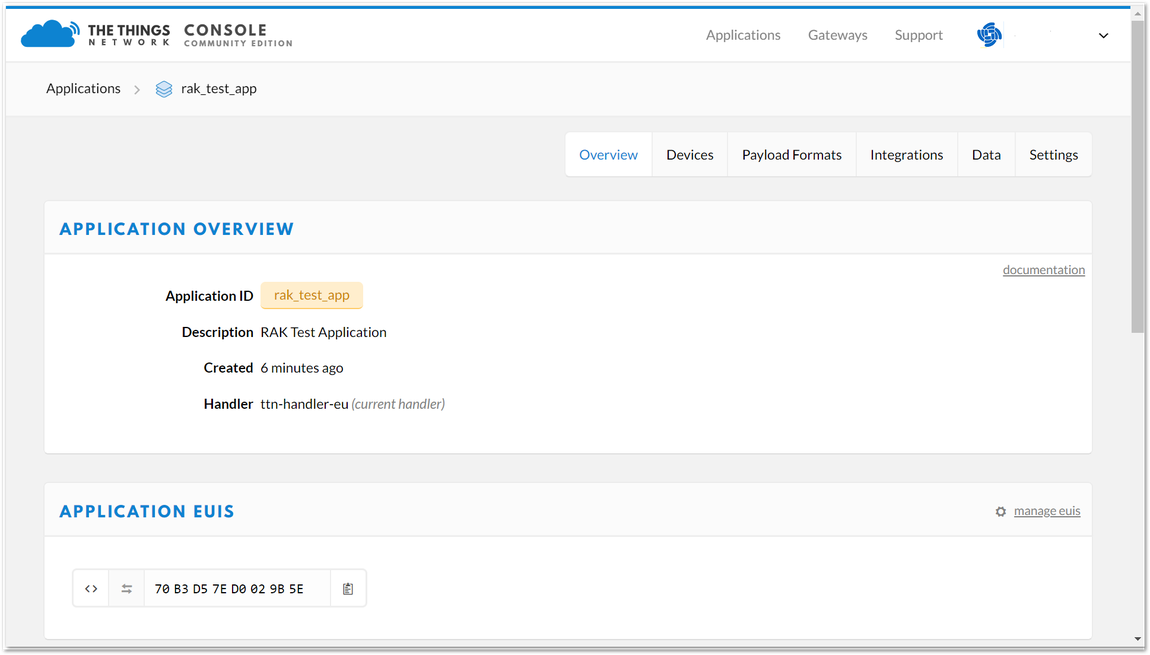 Figure 1: Application Overview
Register Device
- Scroll down until you see the Devices section, or you can also click the "Devices" button at the top.
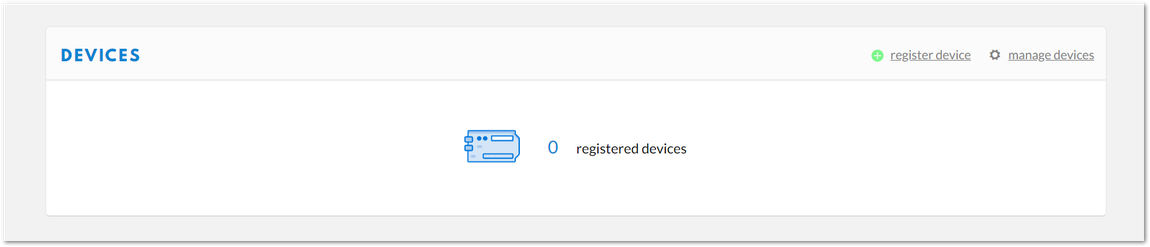 Figure 1: Device Section
- Click "Register device".
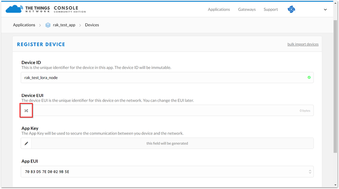 Figure 1: Add your Device
Here are the things that you should take note of in registering your device:
- Device ID - this is the unique identifier for your RAK5205 WisTrio LPWAN Tracker in your application. You need to enter this manually.
- Device EUI - Device EUI of RAK5205 can be found on the sticker label of the RAK811 module. This will ensure you have a unique identification across LoRaWAN networks. You can still change it later, if you want.
The App Key should be in auto generation mode by default.
- Lastly, click the Register button. Now, your device is registered under the corresponding application.
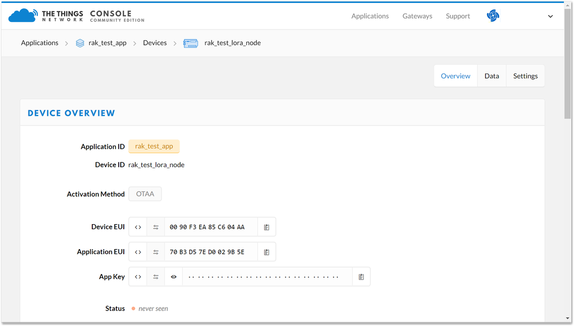 Figure 1: Device Overview
Depending on which authentication method you want to use, proceed to either the OTAA mode or ABP mode section.
OTAA Mode
When setting up a new device in TTN, its default mode is OTAA or Over-the-Air Activation. For configuration, you need the following three parameters: Device EUI, Application EUI, and App Key. You can get them all from the Device Overview page.
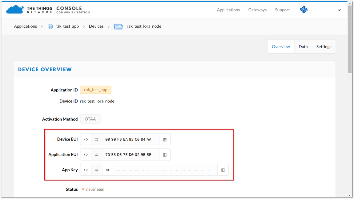 Figure 1: Device OTAA Parameters
Now, configure the RAK5205 to work in OTAA mode in the EU868 band, as an example.
The default LoRa working mode for the RAK5205 is LoRaWAN 1.0.2, while the default LoRa join mode is OTAA, and the default LoRa class is Class A.
- Set mode to OTAA, device class to Class A and your LoRaWAN region to your correct frequency band, with the following set of commands below. Remember to replace XXX with your LoRaWAN region. Refer to RAK5205 Datasheet for your frequency plan.
at+set_config=lora:join_mode:0
at+set_config=lora:class:0
at+set_config=lora:region:XXX
RAK5205 will be sleeping most of the time. You need to input again the command if the reply you get is Wake up.
- Now that RAK5205 is configured to be activated via OTAA, enter these parameters: Device EUI, Application EUI, and App Key using the commands below. Remember to replace the "XXXX" with the corresponding parameter value that matches the LoRaWAN network server.
at+set_config=lora:dev_eui:XXXX
at+set_config=lora:app_eui:XXXX
at+set_config=lora:app_key:XXXX
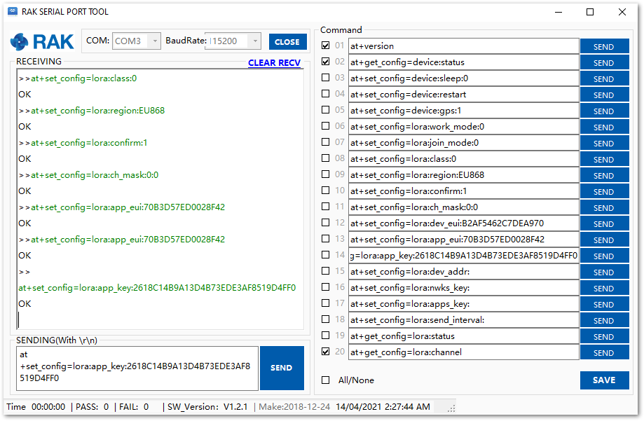 Figure 1: Setting up the RAK5205 OTAA parameters
You should end up with a window like the one in Figure 14 with a series of OK replies.
- Finally, execute the join command. If you join successfully, you will see that the device will start to search for satellite signal.
at+join
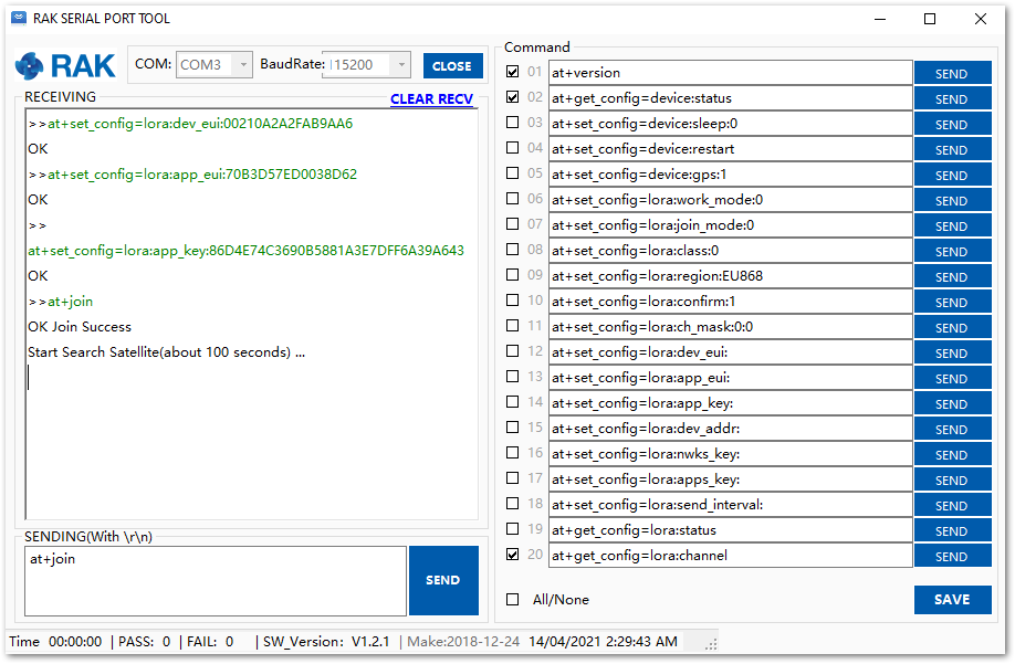 Figure 1: Join command
- After the successful join, the device will automatically send uplinks that contains the sensor readings. This will take a while so you have to wait. If you do not see any transmissions, you can set the time interval via AT command. Also, if you are working indoors on your first setup, you will not see the GPS coordinates on the payload. The GPS needs to fix first.
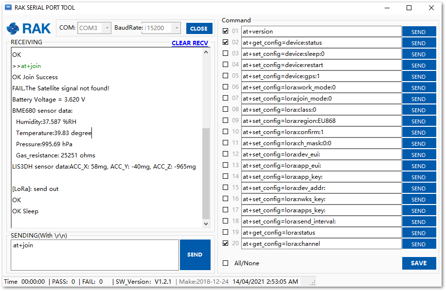 Figure 1: Sending an uplink frame
- If everything works ok, you will get a response in your TTN live data feed as shown in Figure 17.
Be sure that the TTN console is open before sending the data through the RAK Serial Port. Else, you will not be able to see the packet sent.
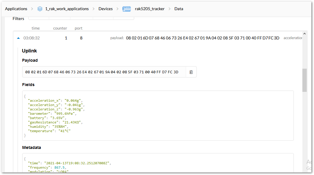 Figure 1: Sending Data to TTN from RAK5205
ABP Mode
-
To join the ABP mode, go to device settings and switch the activation method to ABP.
-
By default, the Device Address, Network Session Key, and App Session Key will be generated automatically.
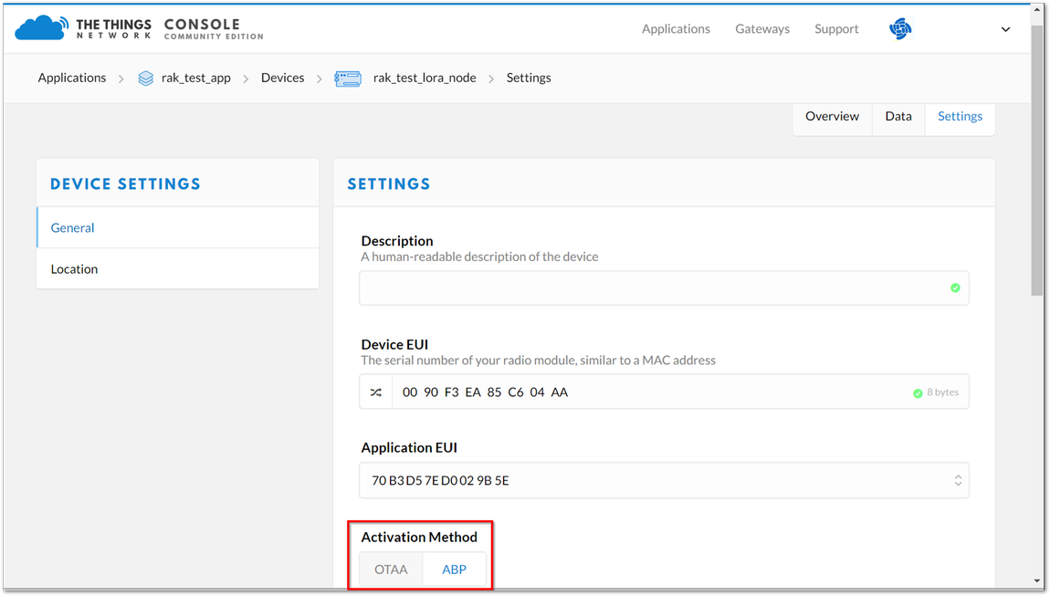 Figure 1: Switching to ABP mode
- Save the mode change and return to the Device Overview page. You can copy the keys by pressing the button after the value fields marked in red in Figure 19.
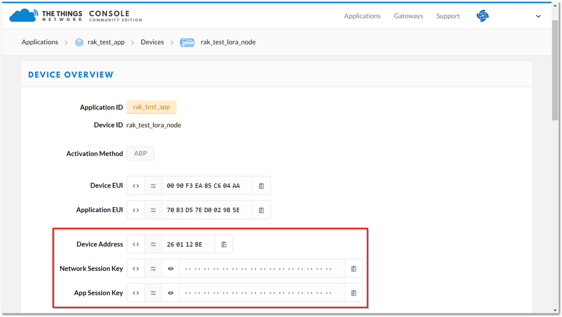 Figure 1: ABP parameters screen
- Set mode to ABP and device class to Class A, respectively. For the LoRaWAN region, set it according to your frequency plan, which can be found in the Datasheet. Replace the XXX with the correct LoRaWAN region. You should end up with a series of OK replies as shown in Figure 20.
at+set_config=lora:join_mode:1
at+set_config=lora:class:0
at+set_config=lora:region:XXX
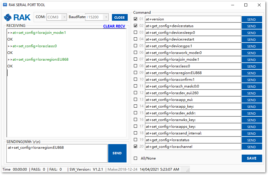 Figure 1: ABP parameters screen
- Now that the mode has been changed, enter the parameters listed which are needed for ABP activation: Device Address, Network Session Key, and Application Session Key. Remember to replace the "XXXX" with the corresponding parameter value that matches the LoRaWAN network server. Refer to Figure 19 for the parameters.
at+set_config=lora:dev_addr:XXXX
at+set_config=lora:nwks_key:XXXX
at+set_config=lora:apps_key:XXXX
- Finally, execute the join command:
at+join
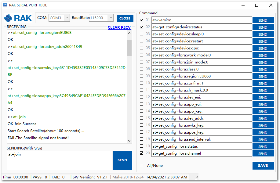 Figure 1: Join command
- After the successful join, the device will automatically send uplinks that contains the sensor readings. This will take a while so you have to wait. If you do not see any transmissions, you can set the time interval via AT command. Also, if you are working indoor on your first setup, you will not see the GPS coordinates on the payload. The GPS needs to be fixed first.
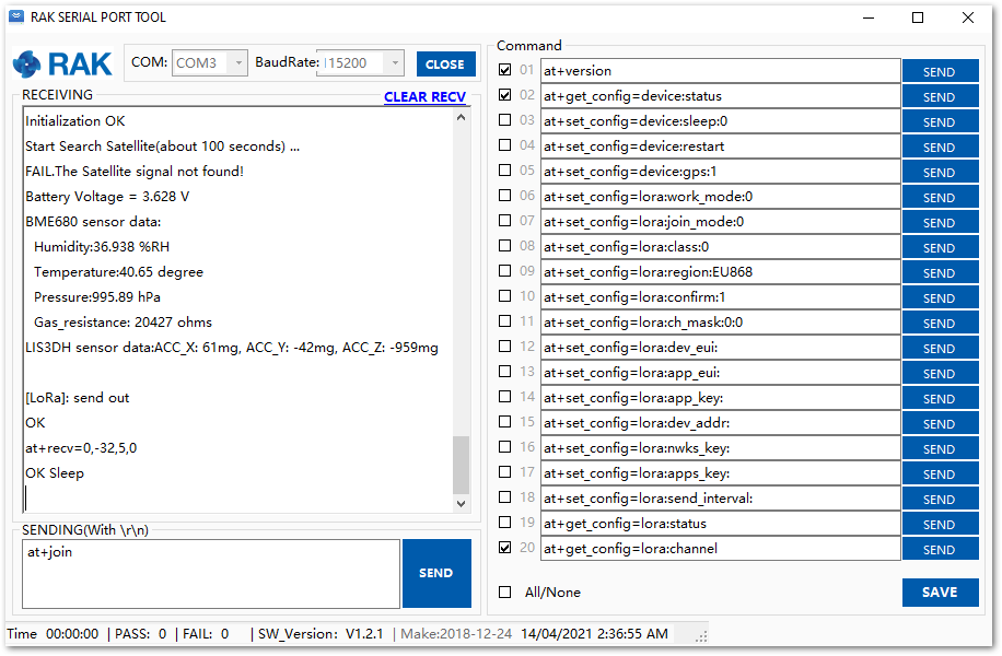 Figure 1: Sending an uplink frame
If you get the same response in your TTN live data feed as shown in Figure 23, then you are all set.
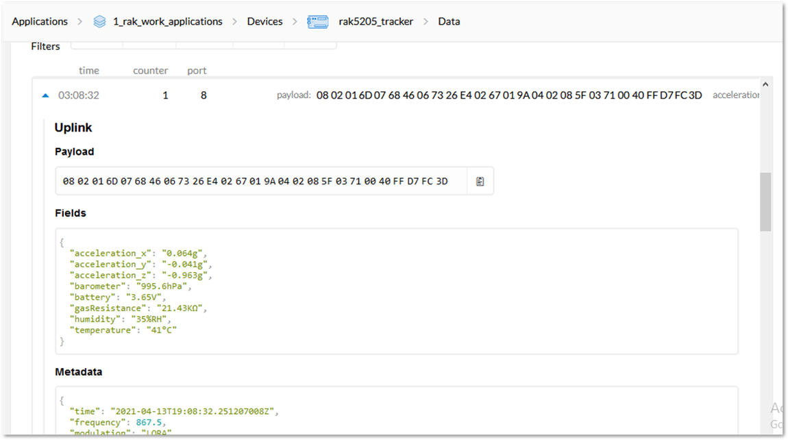 Figure 1: Sending Data to TTN from RAK5205
Connecting to ChirpStack
The ChirpStack or previously known as LoRaServer project provides open-source components for building LoRaWAN networks. To learn more about ChirpStack, visit their website.
You can use RAK5205 to connect with ChirpStack according to the following steps:
In this section, it is assumed that you have already connected your gateway to ChirpStack correctly. If not, look into the RAK Documentation Center of your RAK Gateway in hand.
-
Open the web page of the ChirpStack which you want to connect with and login.
-
By default, there are already one or more items on this page. You can either use it or create a new item, but for this, create a new item by clicking the “CREATE” button.
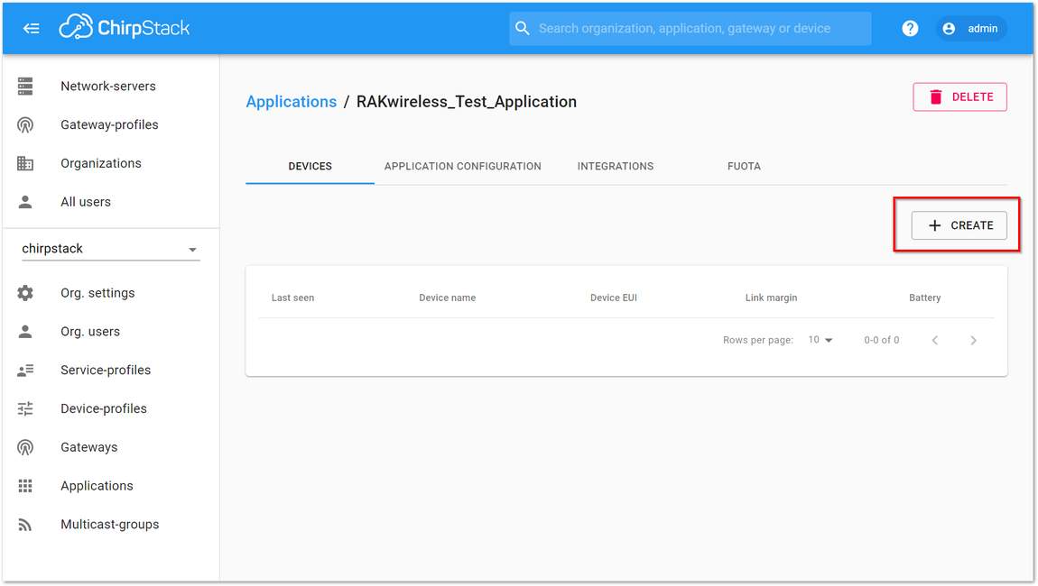 Figure 1: ChirpStack Applications
- Fill up the necessary information, then click "CREATE APPLICATION”.
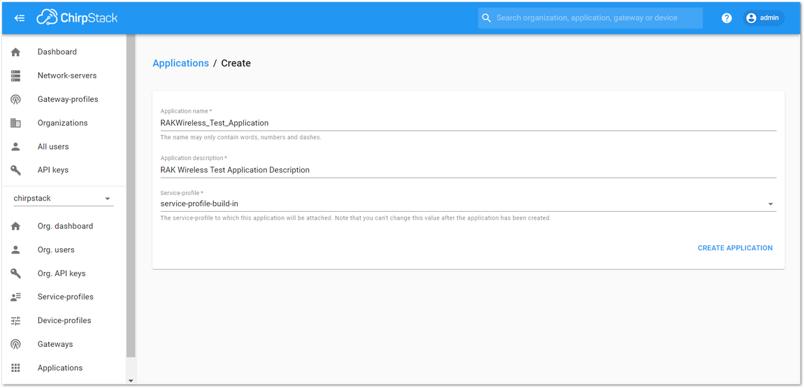 Figure 1: Creating the Application
- Click the new item name “RAKwireless_Test_Application”.
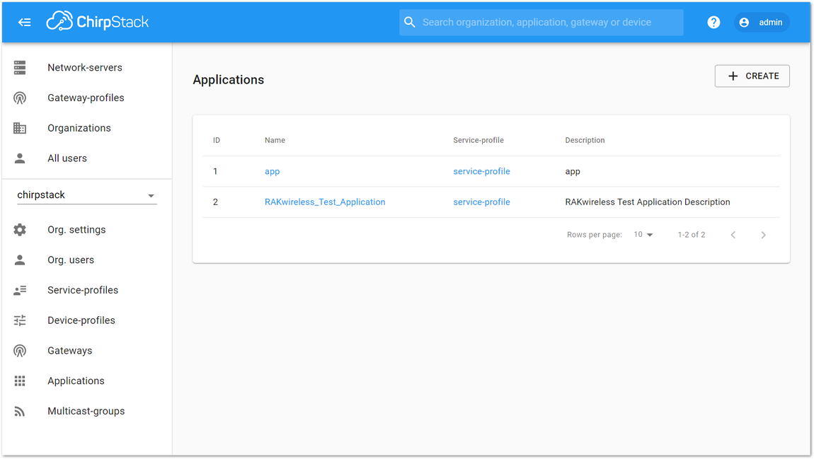 Figure 1: Applications page in ChirpStack
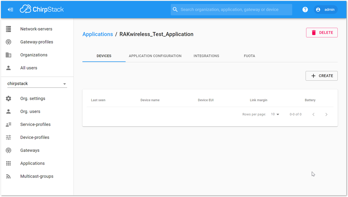 Figure 1: RAKwireless Test Application
- Add a LoRa node device into ChirpStack by clicking the “+ CREATE” button.
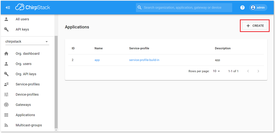 Figure 1: Adding a Node Device
- Fill them in. The Device EUI of RAK5205 can be found on the sticker label of the RAK811 module. Use this to ensure that you have a unique identification across LoRaWAN networks. You can also generate a random Device EUI automatically by clicking the Device EUI icon.
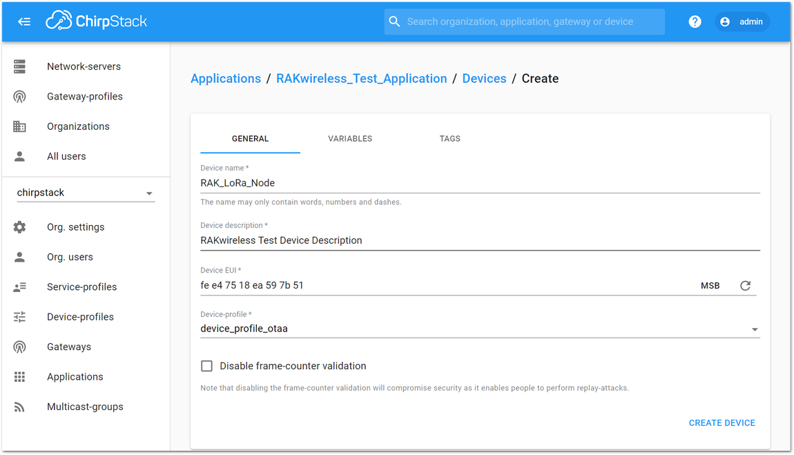 Figure 1: Filling the Device Parameters
- If you want to join in OTAA mode, select “device_profile_otaa” in the “Device-profile” item.
- If you want to join in ABP mode and CN470 frequency, select “DeviceProfile_ABP_CN470” in the “Device-Profile” item.
- If you want to join in ABP mode and other frequencies except for AS923 and CN470, select “device_profile_abp” in the “Device-profile” item.
OTAA Mode
- To join ChirpStack in OTAA mode, select “device_profile_otaa”.
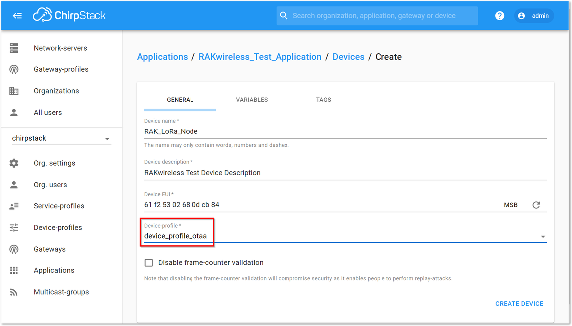 Figure 1: Selecting OTAA Activation Mode in ChirpStack
- Press “CREATE DEVICE” button. You may write the application key by yourself or generate it automatically by clicking the icon highlighted in Figure 31.
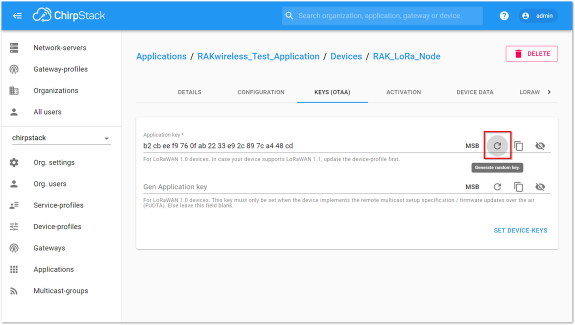 Figure 1: Application Key Generation
- The generated Application Key (App Key) is highlighted in Figure 32.
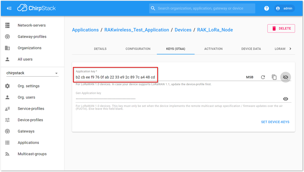 Figure 1: Application Key LoRaWAN
The Application EUI which is set into RAK5205 via AT Command as “app_eui” is not needed for ChirpStack.
-
Click "SET DEVICE-KEYS” button. Now, you’ve completed the configuration on ChirpStack.
-
You should now configure the device via AT commands. Set mode to OTAA, device class to Class A, and your LoRaWAN region to your correct frequency band, with the following set of commands below. Remember to replace XXX with your LoRaWAN region. Refer to RAK5205 Datasheet for your frequency plan.
at+set_config=lora:join_mode:0
at+set_config=lora:class:0
at+set_config=lora:region:XXX
RAK5205 will be sleeping most of the time. You need to input again the command if the reply you get is Wake up.
- Now that RAK5205 is configured to be activated via OTAA, enter these parameters: Device EUI, App EUI, and App Key using the commands below. Remember to replace the XXXX with the corresponding parameter value that matches the Chirpstack network server. You can use the same dev_eui and app_eui when connecting to Chirpstack.
at+set_config=lora:dev_eui:XXXX
at+set_config=lora:app_eui:XXXX
at+set_config=lora:app_key:XXXX
You should end up with a window like the one in Figure 33 with a series of OK replies.
- Finally, execute the join command.
at+join
- You can view the "JoinRequest" and "JoinAccept" on ChirpStack console. The sensor data will be automatically sent in a programmed interval after a successful join. If you do not see any transmissions, you can set the time interval via AT command. Also, if you are working indoor on your first setup, you will not see the GPS coordinates on the payload. The GPS needs to be fixed first.
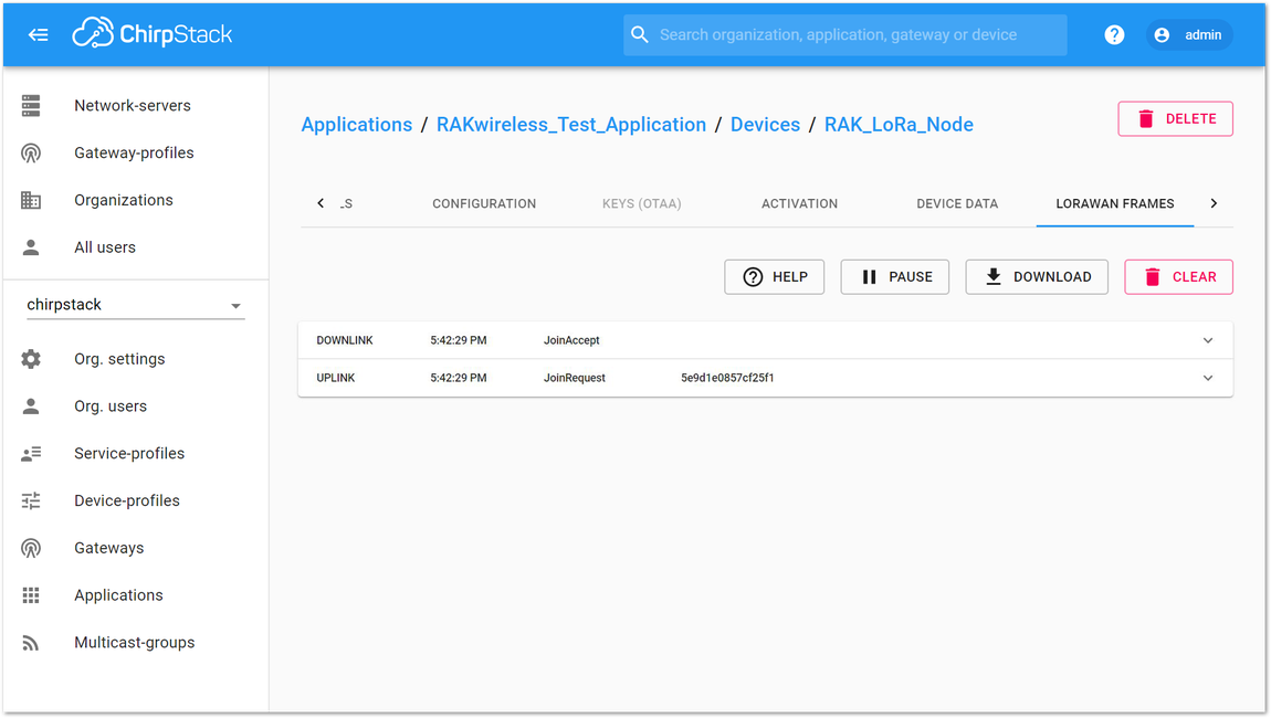 Figure 1: Join Request of the Device in the ChirpStack
ABP Mode
- If you select “device_profile_abp” or “device_profile_abp_cn470”, it means you want to join ChirpStack in “ABP mode”. Fill the parameters “Device name” and “Device description” then click on “CREATE DEVICE” button.
Frequency AS923 in ABP Mode is not supported in Chirpstack.
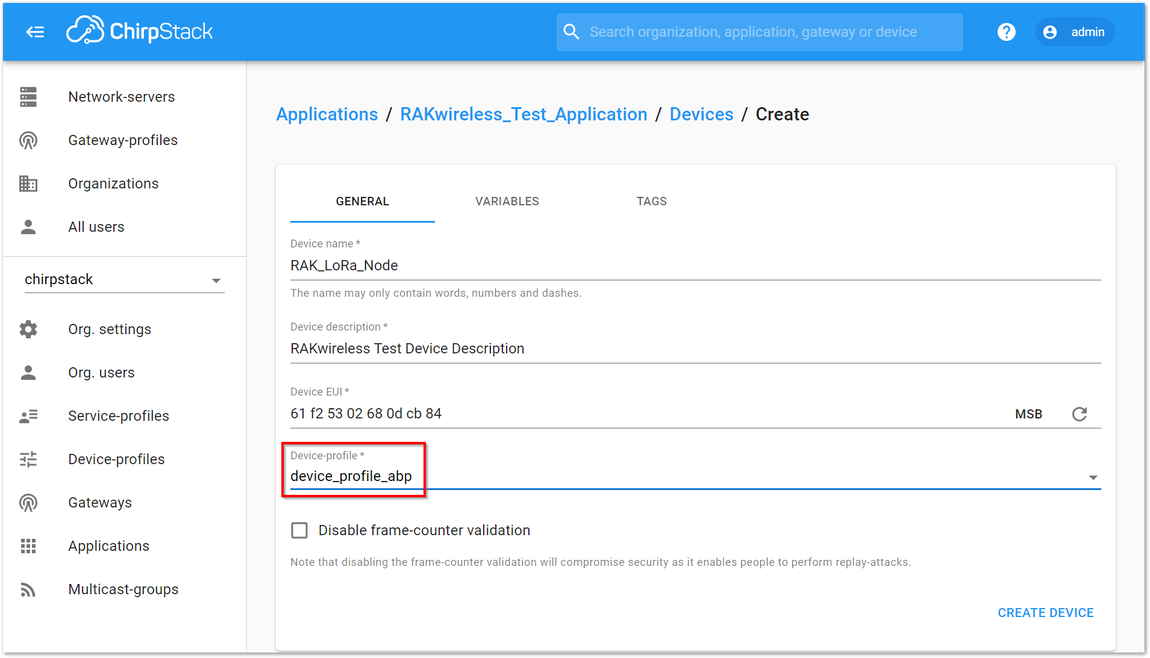 Figure 1: Chirpstack ABP Activation
- Then, you can see that there are some parameters for ABP in the “ACTIVATION” tab.
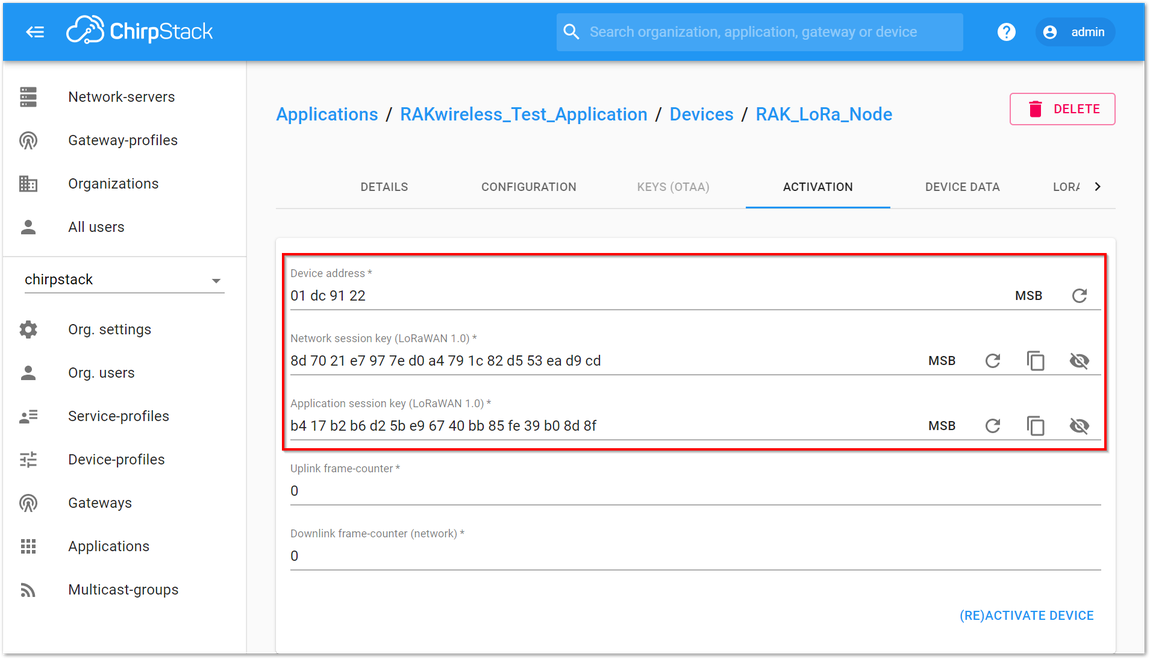 Figure 1: Chirpstack ABP Activation Parameters Needed
- Now that RAK5205 is configured to be activated via ABP, the next step is to setup the device. Set mode to ABP, device class to Class A, and your LoRaWAN region to your correct frequency band, with the following set of commands below. Remember to replace XXX with the your LoRaWAN region. Refer to RAK5205 Datasheet for your frequency plan.
at+set_config=lora:join_mode:1
at+set_config=lora:class:0
at+set_config=lora:region:XXX
- Now that the mode has been changed, enter the parameters listed below which are needed for ABP activation: Device Address, Network Session Key, and Application Session Key. Remember to replace the "XXXX" with the corresponding parameter value that matches the LoRaWAN network server. Refer to Figure 37 for the parameters.
at+set_config=lora:dev_addr:XXXX
at+set_config=lora:nwks_key:XXXX
at+set_config=lora:apps_key:XXXX
- Finally, execute the join command. After a successful join, the sensor data will be automatically sent in a programmed interval. If you do not see any transmissions, you can set the time interval via AT command. Also, if you are working indoor on your first setup, you will not see the GPS coordinates on the payload. The GPS needs to be fixed first.
at+join
Configuration of GPS and Sensor Data
Transmit Interval
With your RAK5205 already connected to the network server, you can set the interval of sending GPS coordinates and sensor data using the following command:
at+set_config=lora:send_interval:1:Y
- where Y represents the time interval is seconds.
GPS Satellite Scan Time and Accuracy
The GPS module will try to get a fix from GPS satellites to get the location coordinates. You can modify the satellite scan time of RAK5205. In addition, you can also set the accuracy of GPS coordinates to 4-digit or 6-digit decimal places.
To set the GPS satellite scan time where X is in seconds:
at+set_config=device:gps_timeout:X
To set the GPS accuracy to 4-digit if X is 0 and 6-digit if X is 1:
at+set_config=device:gps_format:X
Decoding Sensor Data on ChirpStack and TTN
Analyzing Sensor Data from RAK5205
In the previous section, you have successfully sent some raw data from our RAK5205 LPWAN Tracker to The Things Network, but the problem is that you can't really see the actual sensor data from the payload. In this section, you will solve that and understand what each payload means.
Depending on the GPS coordinates accuracy configured on RAK5205 (either 4-digit or 6-digit), you must use the right decoder that can be downloaded on the RAKwireless Github repository.
Take the payload data in Figure 40, for example.
Payload: 01 88 05 37 97 10 9D 59 00 DC 14 08 02 01 7A 07 68 58 06 73 25 6D 02 67 01 1D 04 02 14 AF 03 71 FF FF FF DD FC 2E
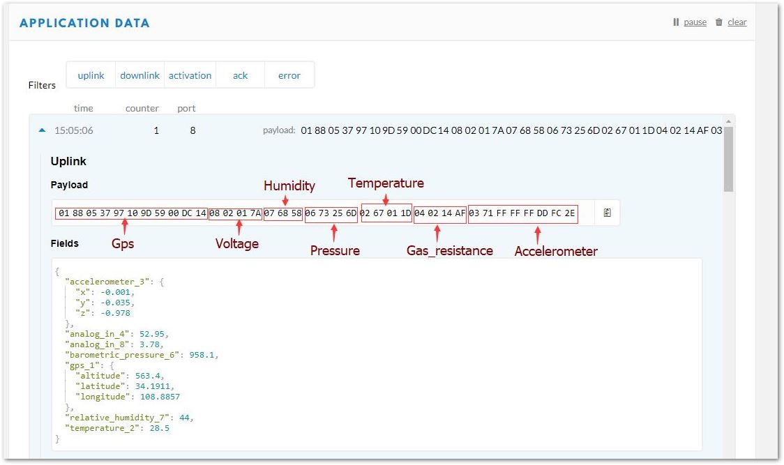 Figure 1: Sample Payload
Now, analyze each piece of data that is in Hexadecimal Format. You will be using the data mentioned above as an example and convert the Hexadecimal Data into Decimal Data using a converter to understand it.
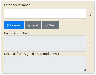 Figure 1: Hexadecimal to Decimal converter
1. GPS Data
Example data: 01 88 05 37 97 10 9D 59 00 DC 14
| Parameter | Hex Data | Decimal Equivalent | Multiplier | True Value |
|---|---|---|---|---|
| Data Flag | 01 88 | |||
| Latitude | 05 37 97 | 341911 | 0.0001° Signed MSB | 34.1911° |
| Longitude | 10 9D 59 | 1088857 | 0.0001° Signed MSB | 108.8857° |
| Altitude | 00 DC 14 | 56340 | 0.01 m Signed MSB | 563.4 m |
2. Battery Voltage
Example Data: 08 02 01 7A
| Parameter | Hex Data | Decimal Equivalent | Multiplier | True Value |
|---|---|---|---|---|
| Data Flag | 08 02 | |||
| Battery Voltage | 01 7A | 378 | 0.01 Signed | 3.78 V |
3. Humidity
Example Data: 07 68 58
| Parameter | Hex Data | Decimal Equivalent | Multiplier | True Value |
|---|---|---|---|---|
| Data Flag | 07 68 | |||
| Humidity | 58 | 88 | 0.5% Unsigned | 44.0% RH |
4. Pressure
Example Data: 06 73 25 6D
| Parameter | Hex Data | Decimal Equivalent | Multiplier | True Value |
|---|---|---|---|---|
| Data Flag | 06 73 | |||
| Pressure | 25 6D | 9581 | 0.1 hPa Unsigned MSB | 958.1 hPa |
5. Temperature
Example Data: 02 67 01 1D
| Parameter | Hex Data | Decimal Equivalent | Multiplier | True Value |
|---|---|---|---|---|
| Data Flag | 02 67 | |||
| Temperature | 01 1D | 285 | 0.1 °C Signed MSB | 28.5 ℃ |
6. Gas Resistance
Example Data: 04 02 14 AF
| Parameter | Hex Data | Decimal Equivalent | Multiplier | True Value |
|---|---|---|---|---|
| Data Flag | 04 02 | |||
| Gas Resistance | 14 AF | 5295 | 0.01 kΩ Signed | 52.95 kΩ |
7. Accelerometer�
Example Data: 03 71 FF FF FF DD FC 2E
| Parameter | Hex Data | Decimal Equivalent | Multiplier | True Value |
|---|---|---|---|---|
| Data Flag | 03 71 | |||
| Acceleration X | FF FF | -1 | 0.001 g Signed MSB | -0.001 g |
| Acceleration Y | FF DD | -35 | 0.001 g Signed MSB | -0.035 g |
| Acceleration Z | FC 2E | -978 | 0.001 g Signed MSB | -0.978 g |
Decoding Sensor Data in TTN
Input Decoding Function in TTN
-
To start with, you need to get the payload decoder depending on the setup of your GPS data:
-
From your TTN console, go to the application page and click the "Payload Formats" tab as shown in Figure 42.
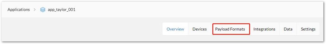 Figure 1: Payload Format at TTN Application Page
- Next, select "Payload Format" as "Custom". Then, from the decoder tab, copy and paste the decoder function from step 1.
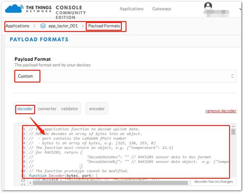 Figure 1: Inputting the Decoder Function
Testing the Validity of Decoding Sensor Data in TTN
Input the hex data below in the "Payload" box as shown in Figure 44.
Payload data: 01 88 05 37 97 10 9D 59 00 DC 14 08 02 01 7A 07 68 58 06 73 25 6D 02 67 01 1D 04 02 14 AF 03 71 FF FF FF DD FC 2E
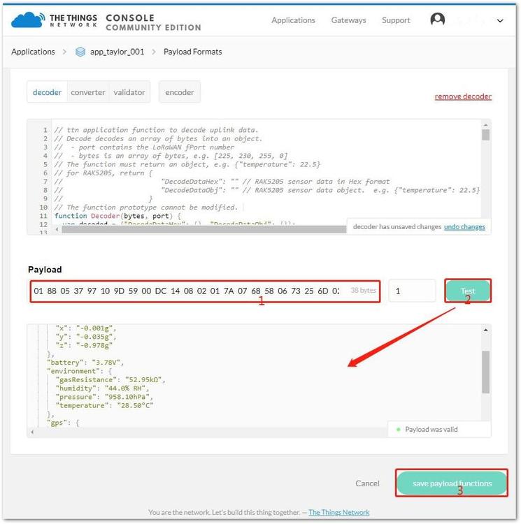 Figure 1: Testing Payload Data
- Then, click "Test" and it will generate a code with the decoded data as also shown in Figure 44.
{
  "DecodeDataHex": "0188053797109d5900dc140802017a0768580673256d0267011d040214af0371ffffffddfc2e",
  "DecodeDataObj": {
    "acceleration": {
      "x": "-0.001g",
      "y": "-0.035g",
      "z": "-0.978g"
    },
    "battery": "3.78V",
    "environment": {
      "gasResistance": "52.95kΩ",
      "humidity": "44.0% RH",
      "pressure": "958.10hPa",
      "temperature": "28.50°C"
    },
	  "gps": {
      "altitude": "563.4m",
      "latitude": "34.1911°",
      "longitude": "108.8857°"
    }
  }
}
- Click "save payload functions" button to save the decoding function.
Testing in Real System in TTN
After the gateway and node go online, click the uplink data record from the application data tab to check the decode status. In Figure 45, you can see the data decoded successfully in TTN.
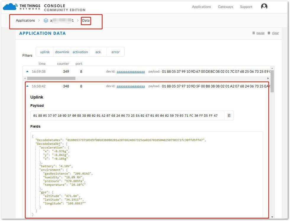 Figure 1: Uplink Decoded Data
Decoding Sensor Data in ChirpStack
Input Decoding Function in ChirpStack
-
To start with, you need to get the payload decoder depending on the setup of your GPS data:
-
From your ChirpStack, go to application page and click the "APPLICATION CONFIGURATION" tab as shown in Figure 46.
 Figure 1: Application Configuration Tab
- Next, select "Payload codec" as "Custom JavaScript codec functions". Then, from the decoder tab, copy and paste the decoder function from step 1.
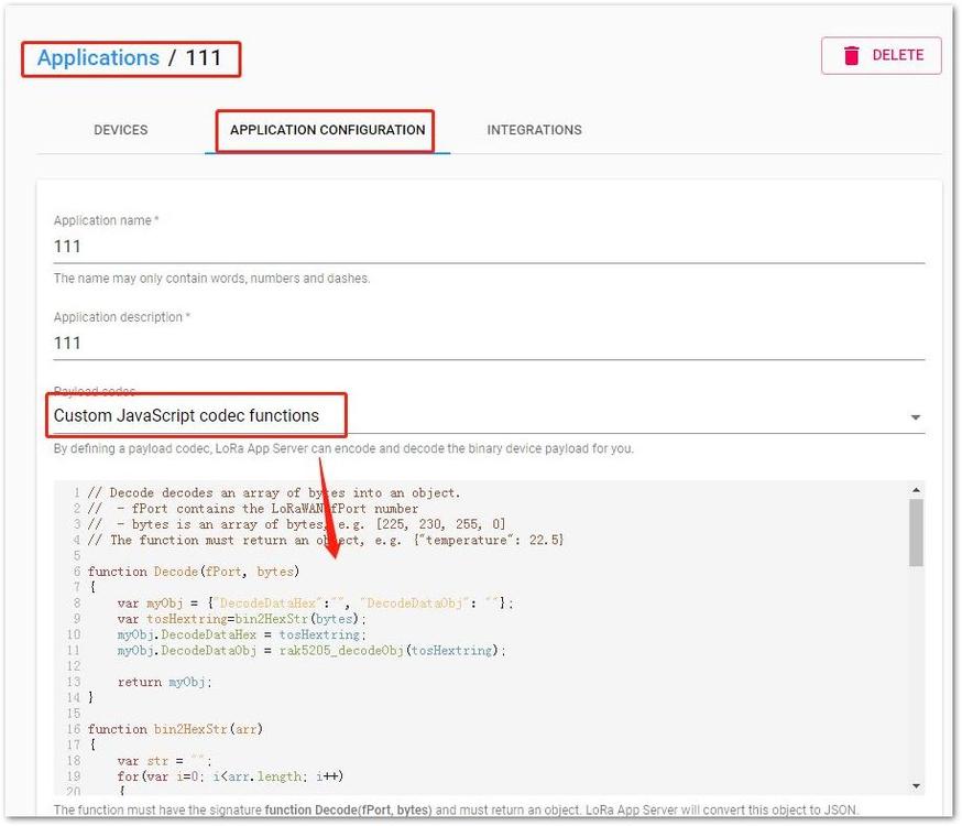 Figure 1: Decoded Function in Chirpstack
- Click "UPDATE APPLICATION" button to save decoding function.
Testing in Real System in ChirpStack
After the gateway and node go online, click the uplink data record from the application data at "LIVE DEVICE DATA" tab to check the decode status. In Figure 48, you can see the data decoded successfully in ChirpStack.
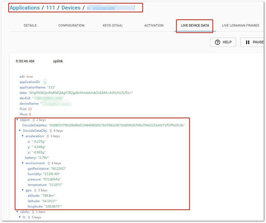 Figure 1: Decode Status in ChirpStack
Cayenne Integration
MyDevice/Cayenne is a service that allows one to monitor node data in real time and can also send downlink control messages. Additionally, it has a wide range of integrations for alerts, notifications, and alarms. Its visualization tools provide various ways of representing both real time and statistical data such as graphs, dials, gauges, scales, and charts.
The Things Network Configuration
Before you can use Cayenne, you need to configure our Application in TTN to properly work with it.
- Log into your TTN Console and navigate to the desired application and RAK5205 device.
- Go to the Payload Formats tab as seen in Figure 49 and choose "Cayenne LPP".
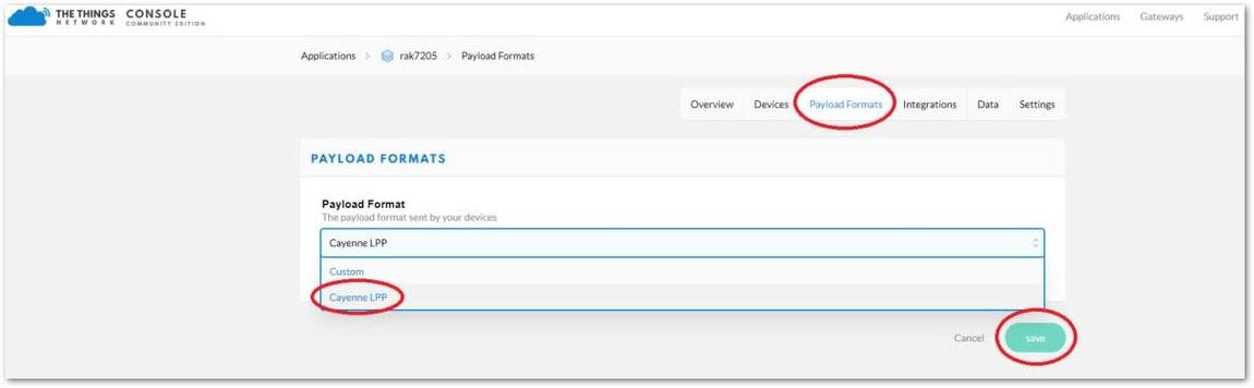 Figure 1: Device Payload Formats
- Next, go to the Integrations Tab and press the "add integration" button.
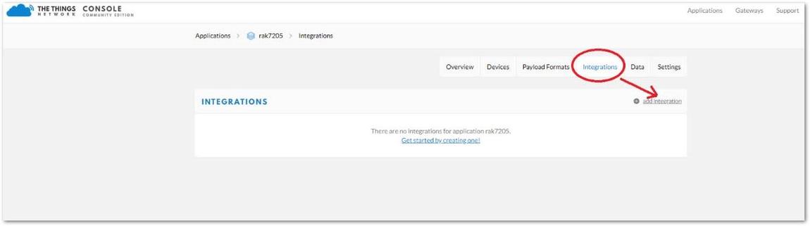 Figure 1: Device Integration
4 Select the MyDevices icon.
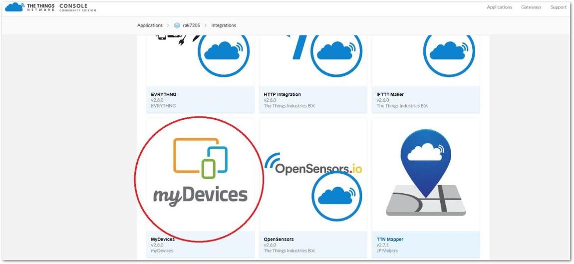 Figure 1: My Devices Integration
- You will be redirected to a page the same as shown in Figure 52, where you need to enter a Process ID and select an Access Key (Choose the default key).
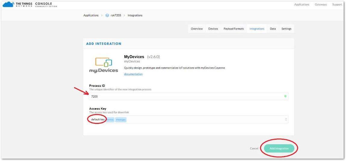 Figure 1: myDevices Integration Configuration
Cayenne Configuration
If you don't have an account in Cayenne, head on to https://mydevices.com/cayenne/signup/ and create an account for free.
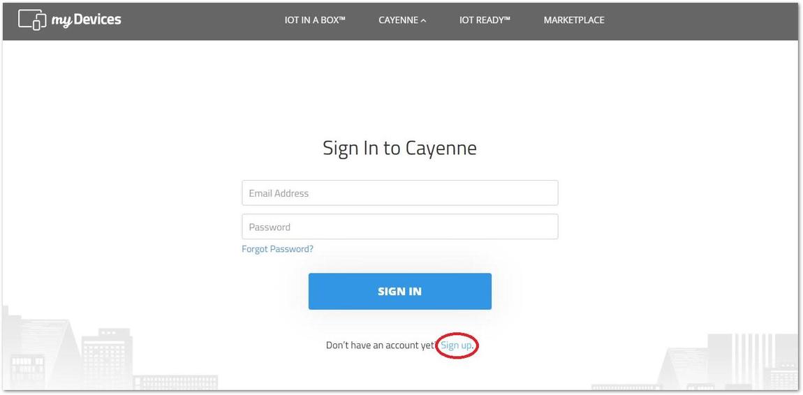 Figure 1: Cayenne start screen
- Once logged in, navigate to the "Add New" drop down menu in the upper left corner and choose "Device/Widget".
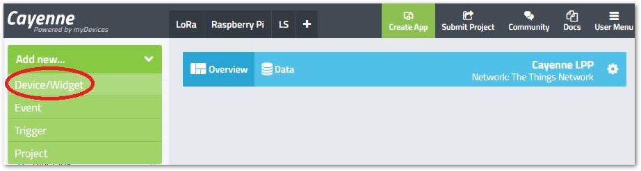 Figure 1: Adding a device
- Select LoRa in the list of Devices and Widgets and navigate to The Things Network at the end of the list.
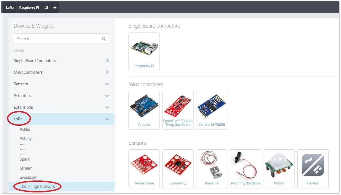 Figure 1: Choosing your device from the list
- A list of LoRa Products and Widgets are now displayed. Scroll down and look for "Cayenne LPP".
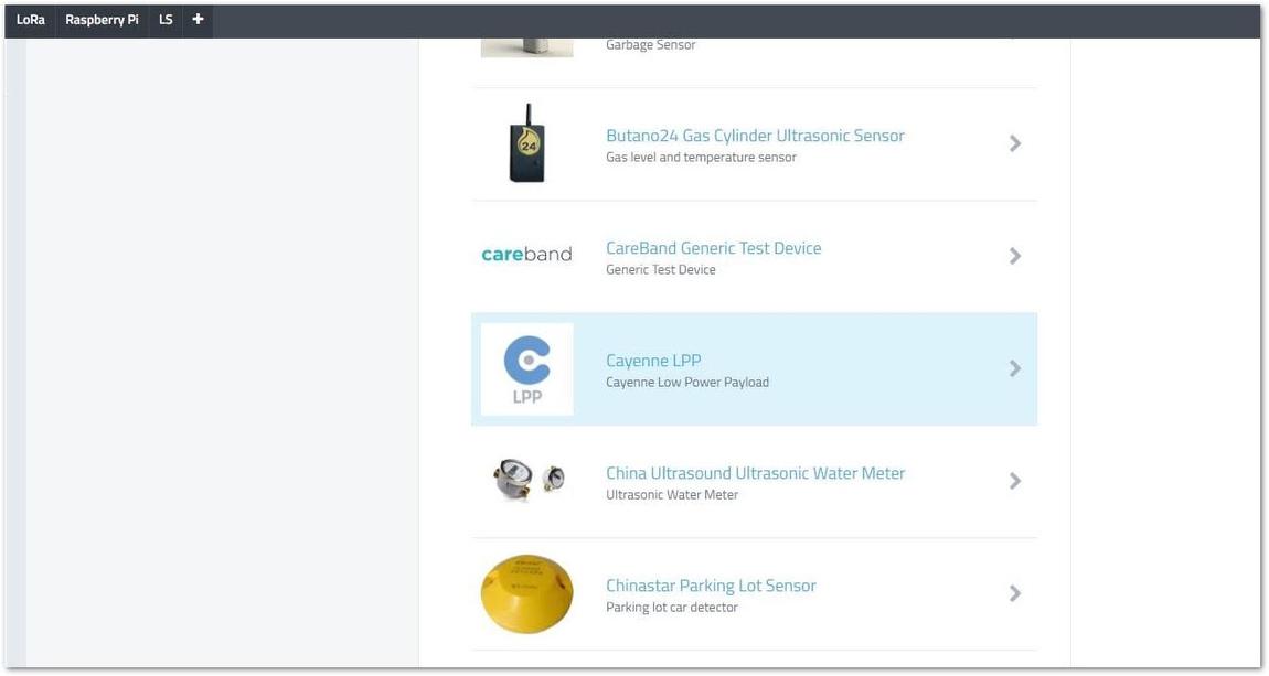 Figure 1: Cayenne LPP device selection
- Lastly, input the Device EUI and optionally set if your device is moving or stationary.
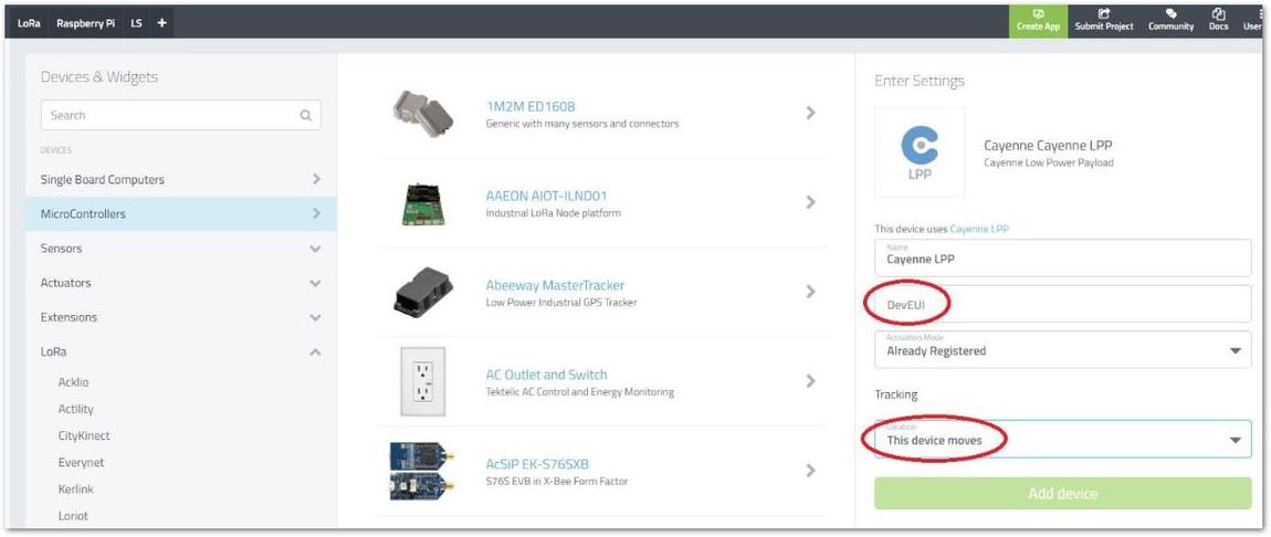 Figure 1: Setting device parameters
- If everything went well, you should end up with a screen the same as Figure 58.
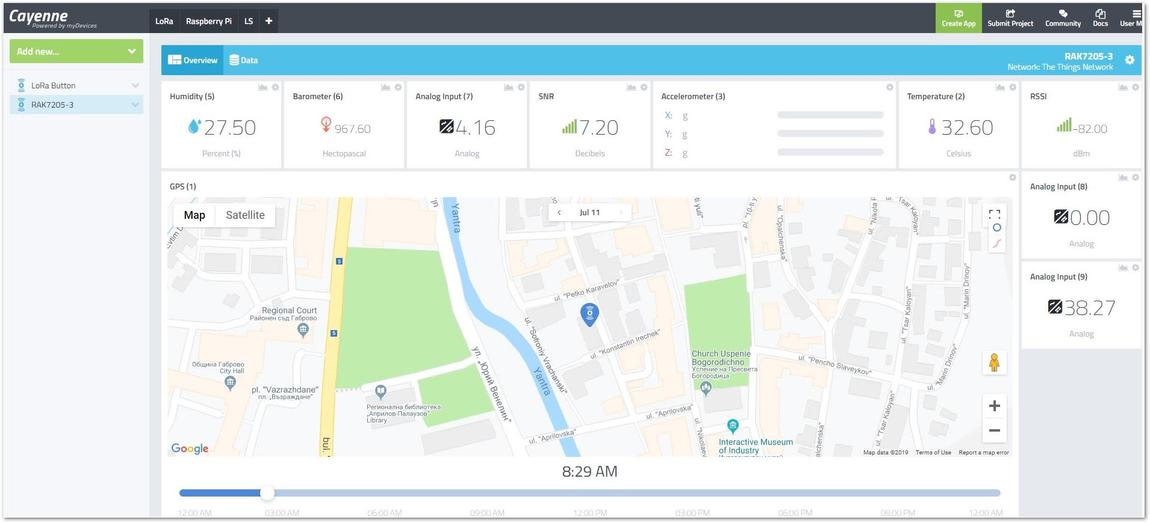 Figure 1: Dashboard live view of RAK5205
There are two widgets that appear as general Analog ones. The first one on channel 8 is the speed as measured by the GPS receiver. The second one on channel 9 is the Air Quality Index (AQI). You need to edit the names and choose an appropriate UI representation by hand. Because, as of this moment, LPP doesn’t support data of such type, and they are transmitted as general analog values. In Rev2 of the LPP standard, it is expected these issues will be addressed.
LoRa P2P Mode
This section shows how to use LoRa P2P mode. You will be using EU868 as the frequency, although it is applicable to other standard bands.
-
First, find two RAK5205 LoRa Tracker which can work on EU868 frequency and make sure their firmware version isn’t less than V3.0.0.1.
-
Next, connect these two RAK5205 LoRa Tracker with PC through UART, and open two serial port tool on PC.
-
Now, configure them to both work in LoRaP2P mode as follow:
at+set_config=lora:work_mode:1
The device will automatically restart when mode is set to LoRa P2P.
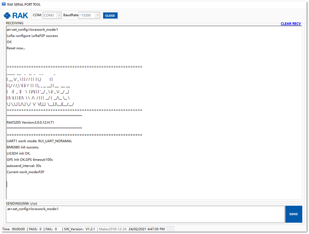 Figure 1: P2P Initialization
- Then configure LoRaP2P parameters for both of them as follow, for example:
at+set_config=lorap2p:869525000:7:0:1:5:5
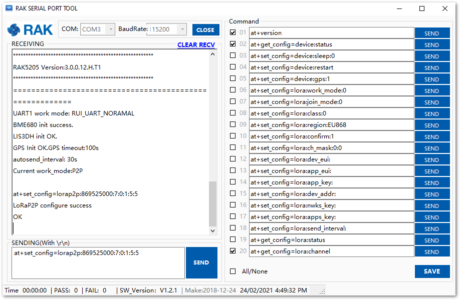 Figure 1: Configuring P2P in both RAK5205 Nodes
- Try to send a message from LoRa Tracker 1 (the left one) to LoRa Tracker 2 (the right one):
at+send=lorap2p:1234567890
In LoRa P2P mode, RAK5205 is in RX mode by default and will automatically switch to TX mode when it needs to transmit data. After the successful transmission, it will go back again to RX mode. You cannot set RAK5202 exclusively as RX or TX mode.
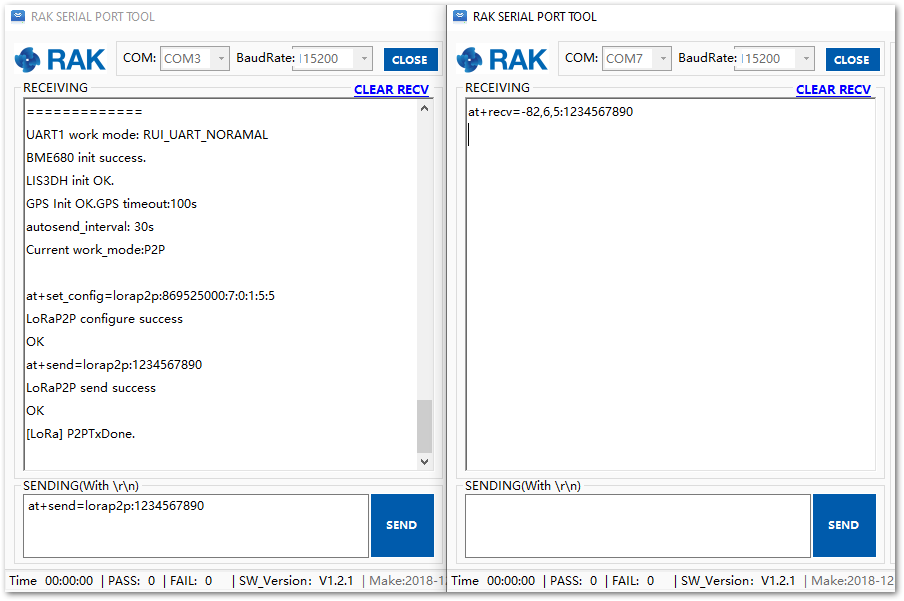 Figure 1: Message sent and received status in the two Nodes
- You can send more messages.
at+send=lorap2p:12345678901234567890
RAK5205 in LoRa P2P mode of operation is also compatible to other RUI based devices like WisDuo modules and others as long as the modules are configured in P2P mode as well.
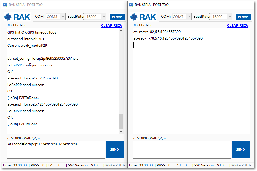 Figure 1: Succeeding Messages sent to the other Node
Now, you have successfully finished your RAK5205 LPWAN Tracker set up.
Miscellaneous
Upgrading the Firmware
If you want to upgrade the latest version firmware of the module, you can follow this section. The latest firmware can be found in the software section of RAK7205/RAK5205 Datasheet.
The FW zip folder will have .hex and .bin firmware files. The .hex file will contain the bootloader plus the application code while the .bin file will contain only the application code.
The procedure of updating the firmware will depend on your current firmware. Follow the guides listed below:
- For devices with current FW version V3.0.0.14 and up, you must use RAK DFU Tool.
- For devices with current FW version V3.0.0.12 and below, you must use STM32CubeProgrammer.
Firmware update using RAK DFU Tool
This firmware update process is for devices with current firmware V3.0.0.14 and up.
-
Download the latest application firmware of the RAK7205/RAK5205.
-
Download the RAK Device Firmware Upgrade (DFU) tool.
-
Connect the RAK7205/RAK5205 to a computer via USB.
-
Open the RAK Device Firmware Upgrade(DFU) v1.4. Select the serial port and baud rate of the module and click the "Select Port" button.
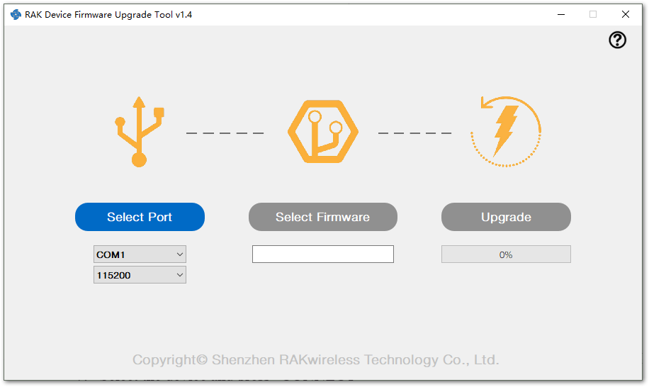 Figure 1: Device Firmware Upgrade Tool
- Select the application firmware file of the module with the suffix ".bin".
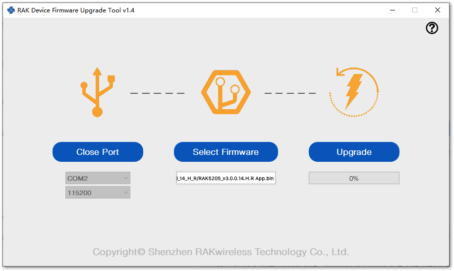 Figure 1: Select Firmware
- Click the "Upgrade" button to upgrade the device. After the upgrade is complete, the RAK7205/RAK5205 device will be ready to work with the new firmware.
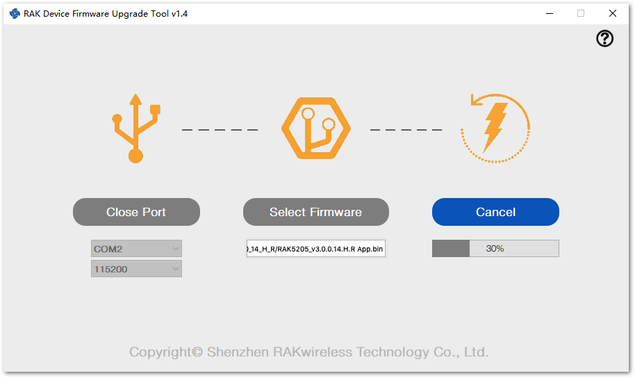 Figure 1: Firmware Upgrading
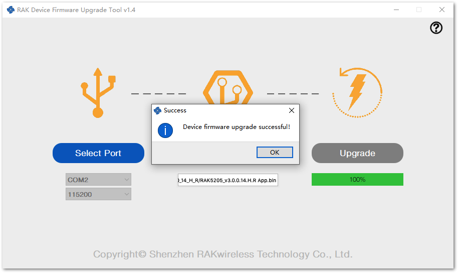 Figure 1: Upgrade Successful
Firmware update using STM32CubeProgrammer
This firmware update process is for devices with current firmware V3.0.0.12 and below.
If you already have a deployed IoT project that uses RAK7205/RAK5205 with firmware version V3.0.0.12 and below, be aware that there will be changes on the AT commands reply when you update your firmware to V3.0.0.14 and up.
-
Download the latest application firmware of the RAK7205/RAK5205.
-
Download and install the STM32CubeProgrammer tool in your PC. You can also get it in the RAK directory.
-
Then, configure your RAK5205 by jumping the “BOOT” pin and “VCC” pin for boot mode. Refer to Figures 67 and 68.
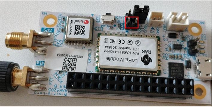 Figure 1: Boot and VCC Pins
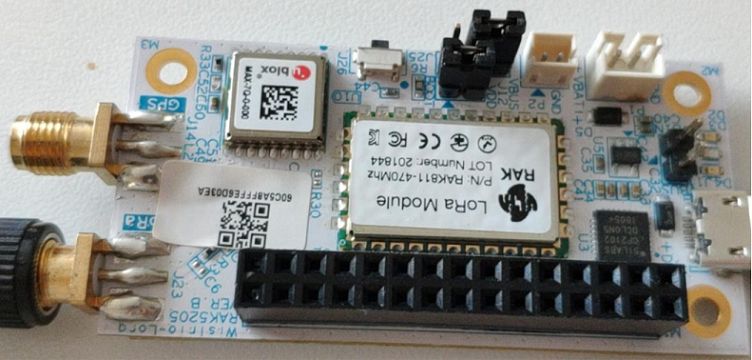 Figure 1: Jumper at Boot and VCC pins
- Connect your RAK5205 to your PC using the USB cable.
The jumper on the BOOT pin must be placed first before connecting to the USB Cable.
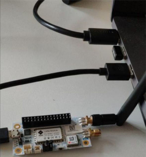 Figure 1: RAK5205 connected to your PC via USB cable
- Choose the correct port number in the COM Port field. You can check this in the Device Manager.
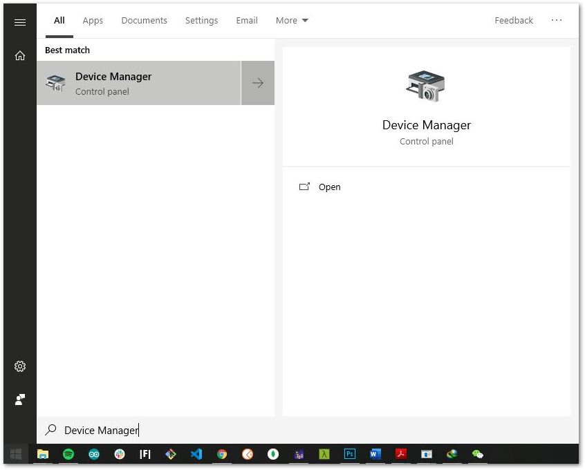 Figure 1: Checking COM Port through Device Manager
-
Open the STM32CubeProgrammer tool.
-
Select UART type. Go to COM Port and look for your RAK5205 Board COM Port (example: COM3).
-
Configure the baud rate and parity.
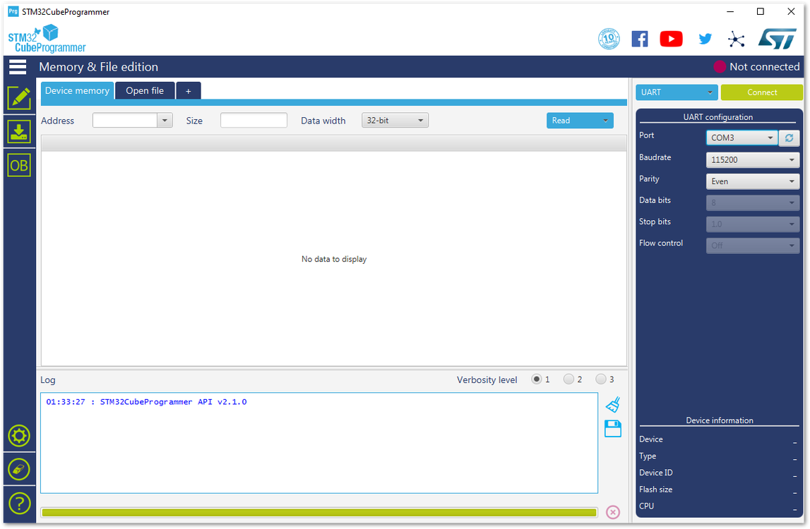 Figure 1: UART Settings in STM32CubeProgrammer
- Then, press the “Connect” button at the top right corner.
If there are some errors in the Log box or it can’t connect, close the STM32CubeProgrammer and reset RAK5205. Then, open the STM32CubeProgrammer and connect again.
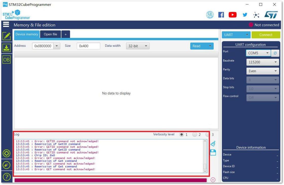 Figure 1: Errors Occurred During Connecting
- You should see a similar log as shown in Figure 73.
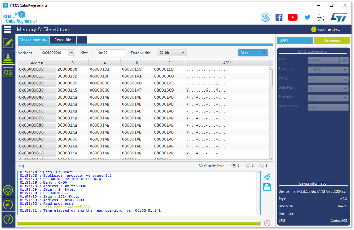 Figure 1: Successful Connection Log to your Device
- Before uploading the firmware, erase all data on the RAK5205 WisTrio LPWAN Tracker as shown on Figure 74.
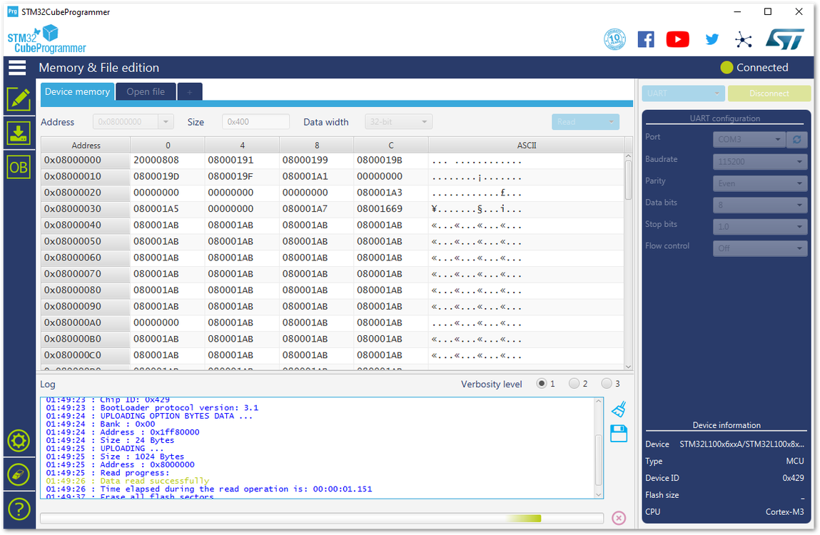 Figure 1: Erasing the Data in the Chip
- Press “Open file” and select the latest RAK5205 firmware file in the pop-up window. Be sure to select the .hex file and not the .bin file.
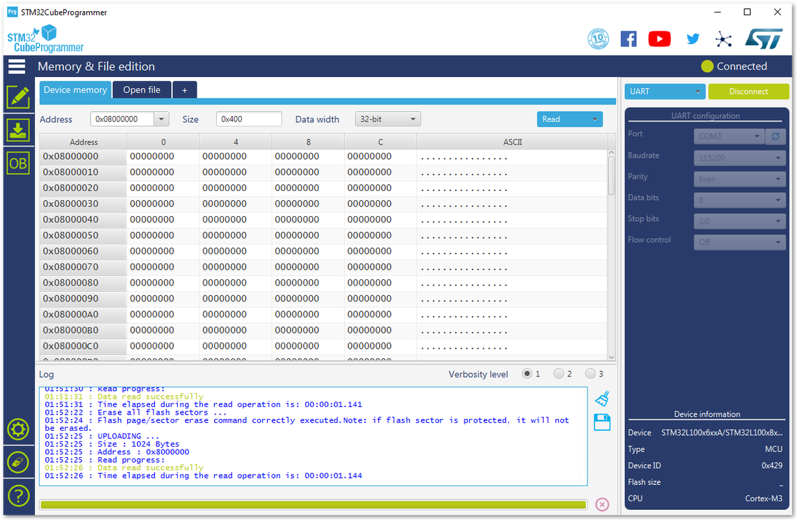 Figure 1: Opening the Bootloader file
- Click the “Download” button to start the burning process.
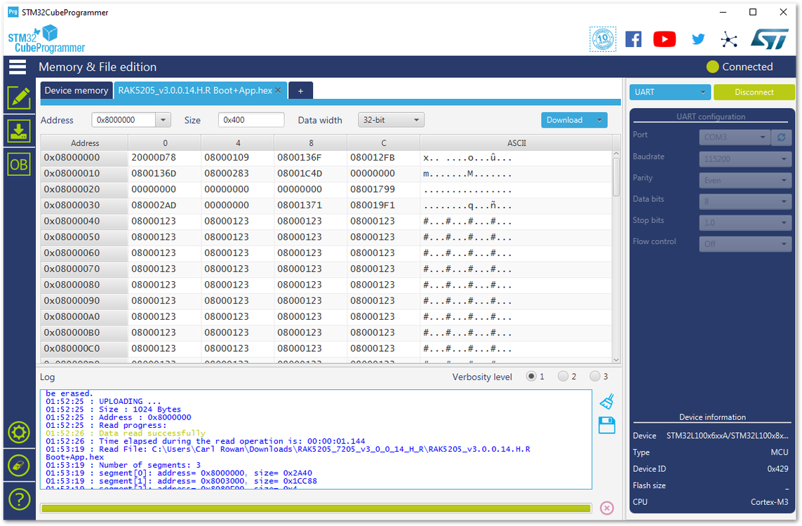 Figure 1: Downloading of Bootloader to the device
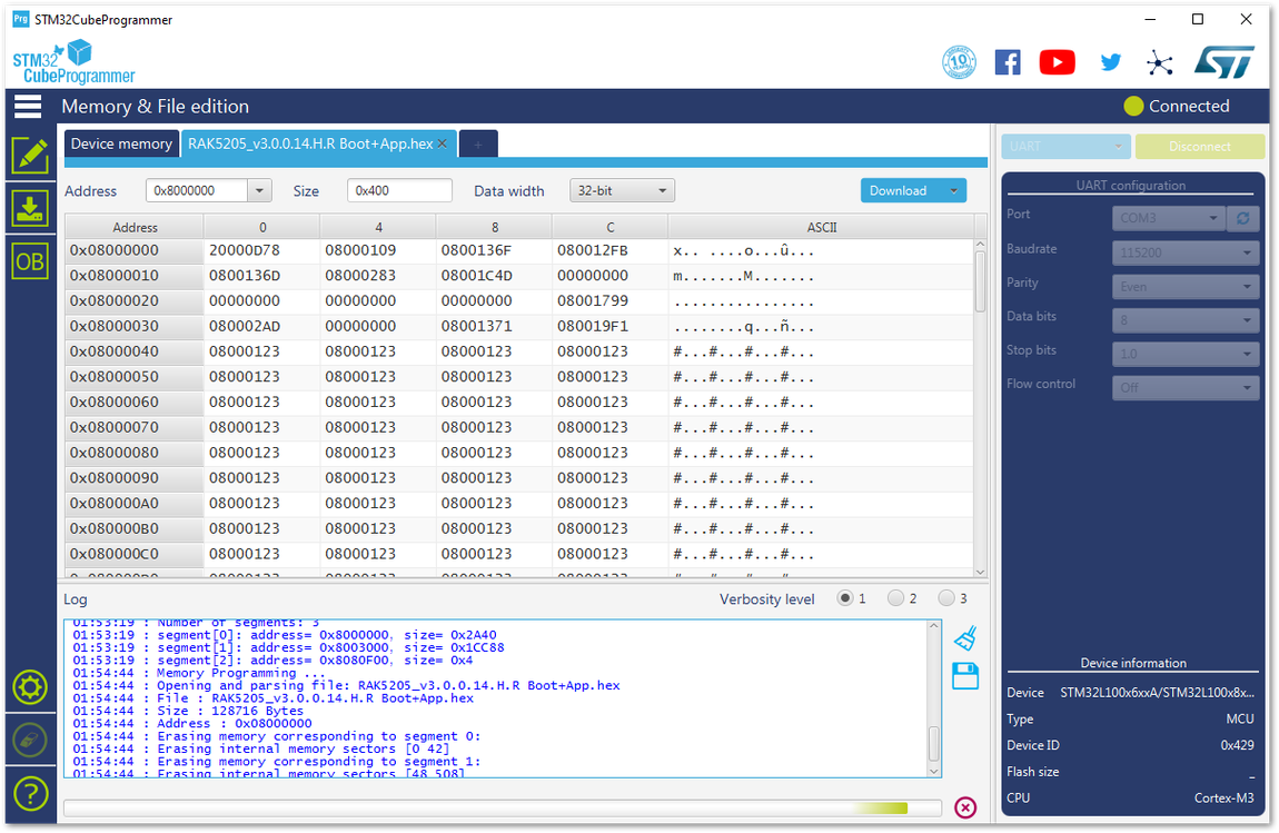 Figure 1: Completing the Download of Bootloader into the device
- Now, you have successfully burned the firmware into RAK5205 WisTrio LPWAN Tracker.
 Figure 1: Successfully Burned the Bootloader to the device
- Disconnect and close the STM32CubeProgrammer tool. Then, power down and remove the connection between BOOT pin and VCC pin to let RAK5205 WisTrio LPWAN Tracker work in normal mode.
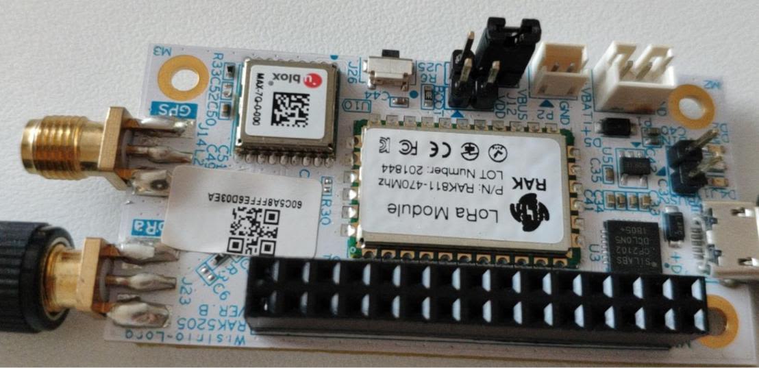 Figure 1: Jumper connection removed
- Connect RAK5205 with your PC’s USB interface again. Open your serial port tool and check your firmware version shown in Figure 80.
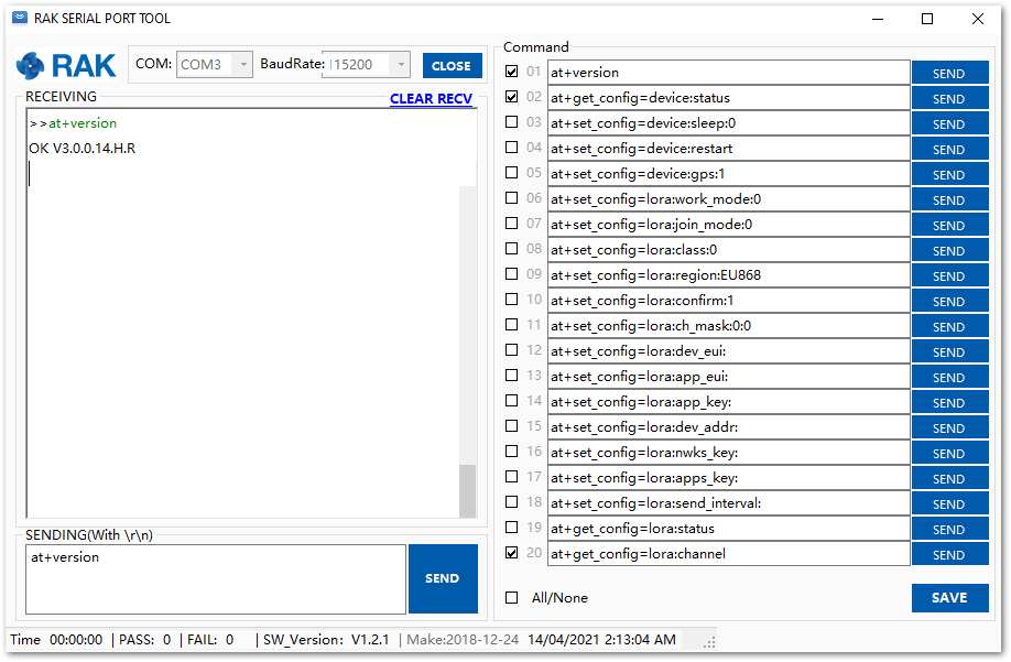 Figure 1: Updated Firmware
Legacy Firmware Support (V3.0.0.12)
If you still need to use V3.0.0.12, this is the guide you should follow. The first step is to upload the bootloader code to the RAK7205/RAK5205. Then update the FW using LoRa Button FW update software.
-
Download the legacy bootloader hex file of the RAK7205/RAK5205 compatible to FW V3.0.0.12.
-
Download and install the STM32CubeProgrammer tool in your PC. You can also get it in the RAK directory.
-
Then, configure your RAK5205 by jumping the “BOOT” pin and “VCC” pin for boot mode. Refer to Figures 81 and 82.
Figure 1: Boot and VCC PinsFigure 1: Jumper at Boot and VCC pins- Connect your RAK5205 to your PC using the USB cable.
The jumper on the BOOT pin must be placed first before connecting to the USB Cable.
Figure 1: RAK5205 connected to your PC via USB cable- Choose the correct port number in the COM Port field. You can check this in the Device Manager.
Figure 1: Checking COM Port through Device Manager-
Open the STM32CubeProgrammer tool.
-
Select UART type. Go to COM Port and look for your RAK5205 Board COM Port (example: COM3).
-
Configure the baud rate and parity.
Figure 1: UART Settings in STM32CubeProgrammer- Then, press the “Connect” button at the top right corner.
If there are some errors in the Log box or it can’t connect, close the STM32CubeProgrammer and reset RAK5205. Then, open the STM32CubeProgrammer and connect again.
Figure 1: Errors Occurred During Connecting- You should see a similar log as shown in Figure 87.
Figure 1: Successful Connection Log to your Device- Before uploading the firmware, erase all data on the RAK5205 WisTrio LPWAN Tracker as shown on Figure 88.
Figure 1: Erasing the Data in the Chip- Press “Open file” and select the bootloader file in the pop-up window.
Figure 1: Opening the Bootloader file- Click the “Download” button to start the burning process.
 Figure 1: Downloading of Bootloader to the device
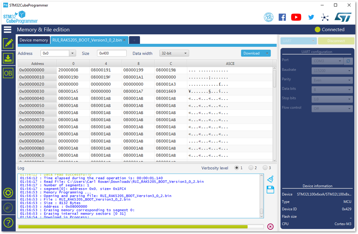 Figure 1: Completing the Download of Bootloader into the device
- Now, you have successfully burned the firmware into RAK5205 WisTrio LPWAN Tracker.
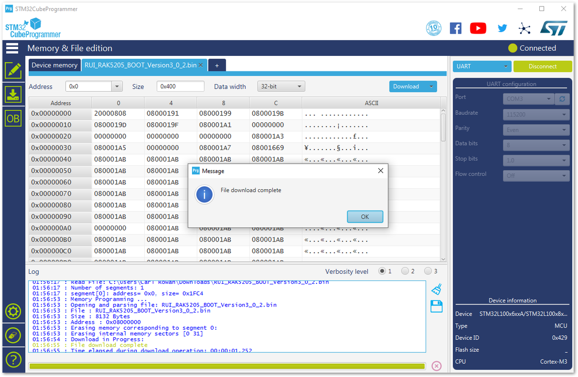 Figure 1: Successfully Burned the Bootloader to the device
- Disconnect and close the STM32CubeProgrammer tool. Then, power down and remove the connection between BOOT pin and VCC pin to let RAK5205 WisTrio LPWAN Tracker work in normal mode.
Figure 1: Jumper connection removed- Connect RAK5205 with your PC’s USB interface again. Open your serial port tool check the version as shown in Figure 94. If it shows the RUI Bootloader Version, the device is now on bootloader mode and ready to get the application firmware.
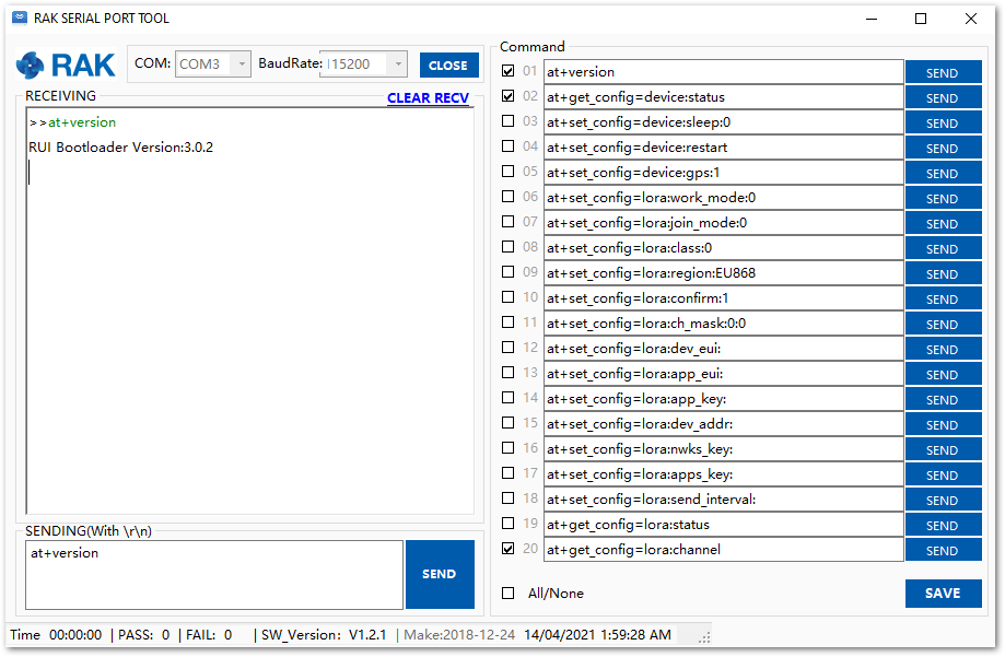 Figure 1: Successfully Downloading the Bootloader
-
You can now on the second step which is burning the V3.0.0.12 firmware into RAK7205/RAK5205 using the LoRa Button Upgrade Tool.
-
Download the RAK Upgrade Tool V1.0. Then, extract and open the tool.
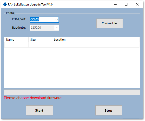 Figure 1: RAK Upgrade Tool
- Get the RAK5205 V3.0.0.12 Firmware from RAKwireless download site and click “Choose File” button to select the firmware file.
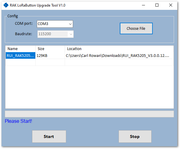 Figure 1: Choosing the Correct Upgrade file
- Click “Start” to upgrade. This may take a minute.
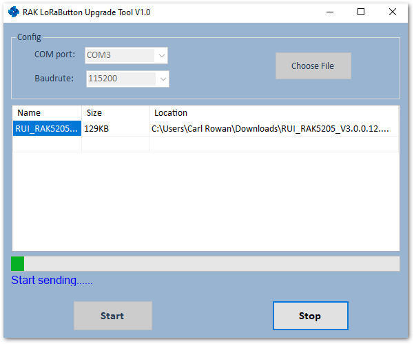 Figure 1: Start Upgrading your Firmware
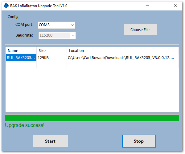 Figure 1: Successfully Upgraded your Firmware
- Now, close the upgrade tool and open a serial port tool to configure your RAK5205.
- It is recommended to use the RAK Serial Port Tool because there are some ready AT commands in this tool which very useful for you. You can get it from the RAK directory for free.
- Choose the correct COM port and set the baud rate to 115200. Then open the serial port and check the firmware version.
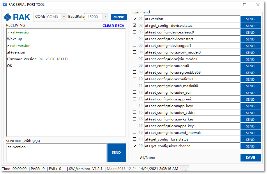 Figure 1: V3.0.0.12 Firmware
You have successfully upgraded the new firmware.
Assembly Guide for RAK5205 Enclosure
This section provides you assistance when installing the Tracker Node Enclosure of your RAK5205.
Assembly List
The assembly includes the following
- 1x Enclosure
- 1x Installation Kit
- 1x LoRa Antenna
- 1x GPS Antenna
- 1x Supporting Plate
- 4x M16, 2x M12 Cable Gland Covers
- 1x PCB
- Battery and Adhesive
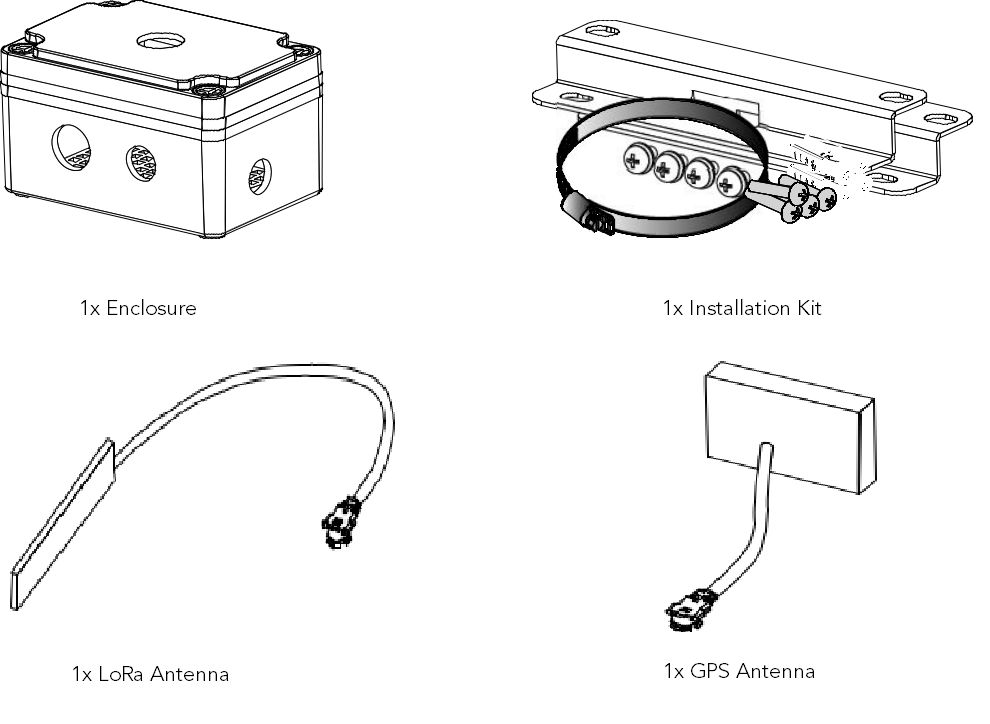 Figure 1: Assembly List
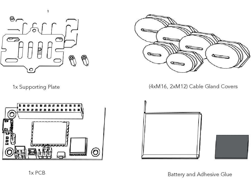 Figure 1: Assembly List
-
To start with, assemble the cover of your RAK5205 enclosure.
a. If a solar panel is necessary, attached it to the cover, using silicon glue, as shown in Figure 102.
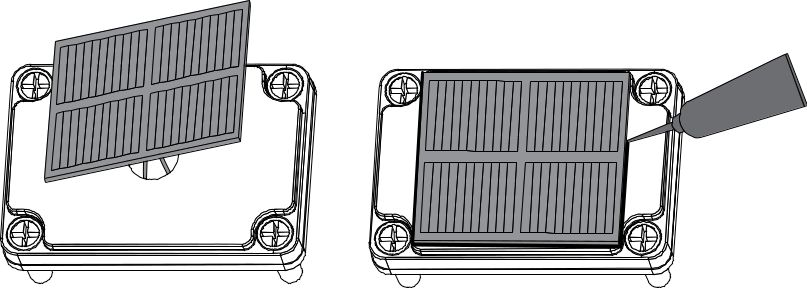 Figure 1: Attached Solar Panel in Cover
b. If not, then directly plug the opening cover with M16 Dome plug.
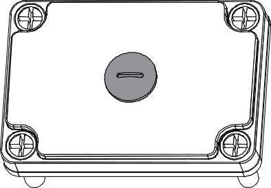 Figure 1: Inserting Plug in Cover with no Solar Panel
- Install the Supporting Plate along with the two M4x5 screws as shown in Figure 104.
 Figure 1: Installed Supporting Plate
- Using the three M16 Dome plugs and two M12 Dome plugs, plug the opening of the bottom shell (left of Figure 105). Then, if an external antenna or an external interface is needed, replace the corresponding hole with the corresponding cable (right).
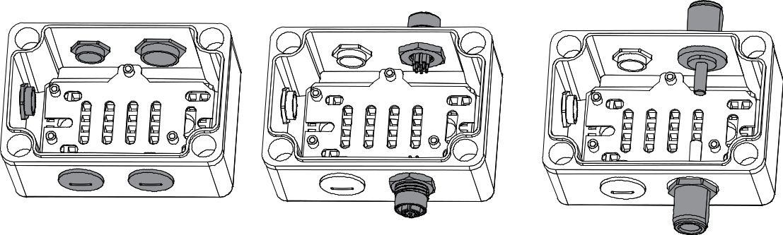 Figure 1: Opening for External Antenna
- Fix the PCB in the enclosure using the three M2.5x4 screws.
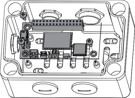 Figure 1: Fixing of RAK5205 in Enclosure
- Attach the LoRa and GPS antenna to the bottom shell. The LoRa antenna is glued above the M12 Dome plug while the GPS is on the shorter side, as shown in Figure 107.
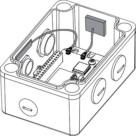 Figure 1: Attached GPS and LoRa Antenna
- Install two M2.5x15 hexagonal standoffs.
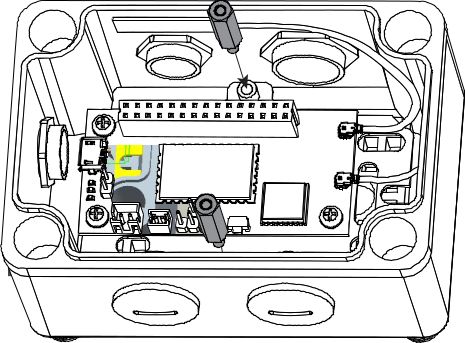 Figure 1: Installed Hexagonal Standoffs
- Plug the connector of the battery into the socket of the PCB. If you use solar panels, then connect the cable to the PCB. After that, fix the supporting plate on the standoff with two M2.5x4 screws.
Figure 1: Fixed Supporting Plate and Battery Cable Connected- Remove the double-sided adhesive on the surface of the battery and attached it to the supporting plate.
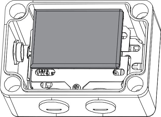 Figure 1: Attaching of Battery in Supporting Plate
- Lastly, install the cover.
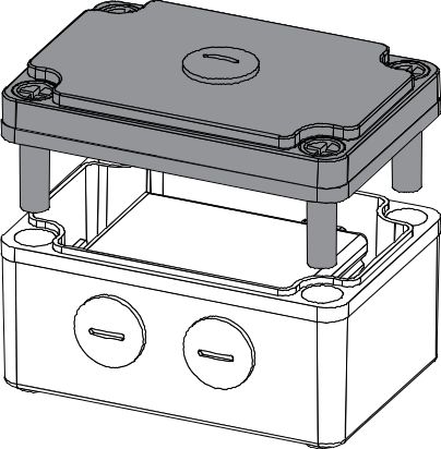 Figure 1: Enclosure Cover Installed
Installation
Wall Mounting
- Fix the installation kit on the bottom of the enclosure with four M5x10 screws.
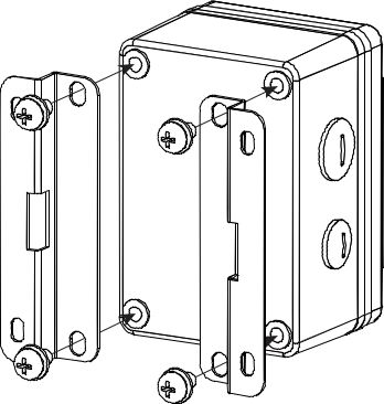 Figure 1: Fixing Installation Kit
- Using a Ø5 mm drill head, drill four holes on the wall according to the dimension shown in Figure 113, and then plug the screw anchors in the wall.
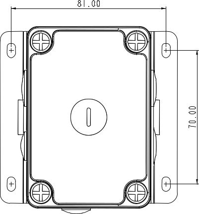 Figure 1: Drill Holes into Wall according to this Dimension
- Using the tapping screws, attach the device to the wall.
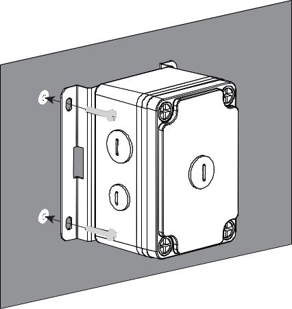 Figure 1: Mounting of Enclosure in Wall
Pole Mounting
- The same with wall mounting, first, fix the installation kit on the bottom of the enclosure with four M5x10 screws.
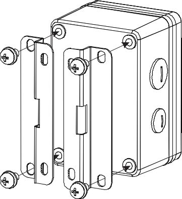 Figure 1: Installation Kit Attached in Enclosure
- Slide the steel band clamps through the rectangular hole of the mount kit. Then, wrap the band clamps around the pole, lock them, and tighten the clamps using a screwdriver.
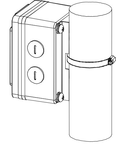 Figure 1: Enclosure Clamped around the Pole