All-in-One. 5G LTE Radio Configuration User Manual
This document describes the configuration of the All-in-One. 5G LTE eNodeB (eNB) for software version BaiBS_QRTA_2.11.x_RAK. It explains how to configure the device after installation.
Overview
The All-in-One. 5G LTE eNodeB (eNB) is loaded with its own GUI for configuring its operating parameters. You can log in to the GUI locally through the Local Maintenance Terminal (LMT), an Ethernet port, or remotely via an IP address.
When configuring a newly installed eNB, refer to the recommended configuration flow shown in Figure 1.
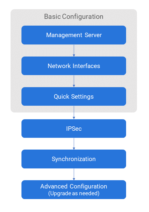 Figure 1: eNB Configuration Flow
Before configuring the eNB’s data, data planning must be done first. The data to configure the eNB includes local parameters and network parameters. These parameters are either provided by the user or determined after negotiation with the customers.
The data to prepare includes transmission parameters, wireless parameters, operation and maintenance parameters, and software version.
If the eNB works in SAS mode, set the Country Code to USA-FCC (CBRS).
Login Client Web
Client Web Environmental Requirements
Table 1: Client Environmental Requirements
| Item | Description |
|---|---|
| CPU | Intel core above 1 GHz |
| Memory | Above 2G RAM |
| Hard disk | Usable space should be >100 MB |
| Operating system | Microsoft: Windows XP, Windows Vista, Windows 7 or Windows 10 Mac: macOS X 10.5 or above |
| Screen resolution | Above 1024 x 768 |
| Browser | Chrome 6 or higher |
Connect Client Web to eNB
Connect the computer Ethernet interface to the base station LAN interface with an Ethernet cable.
Set Up Client Computer
Before logging into the Web client, the client computer’s IP address needs to be set up first so that the connection between the client and the server is possible.
Take Windows 7 as an example:
- Click Start > Control Panel.
- A window will pop up, then choose Network and Internet.
- Click View network status and tasks, then select Local Connectivity.
- In the Status of Local Connectivity, click Properties to see the Properties of Local Connectivity pop-up window.
- Select Internet Protocol Version (TCP/IPV4), and click Properties to see the pop-up window, as shown in Figure 2.
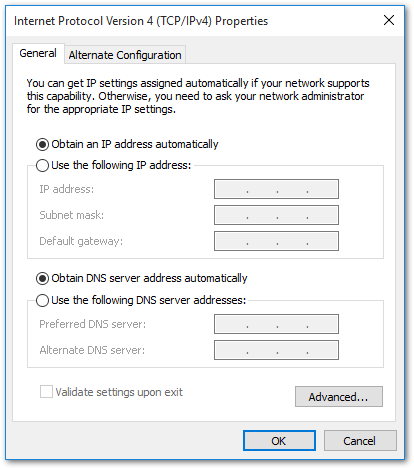 Figure 1: Internet Protocol version (TCP/IPV4)
- Select either Obtain an IP address automatically or Use the following IP address.
- If Obtain an IP address automatically is selected, go directly to Step 9.
- If Use the following IP address is selected, follow Steps 7 to 9.
In general, if auto-obtaining fails, you need to set up the IP address manually.
-
Select Use the following IP address.
-
Input the following, and then click OK:
- IP address:
192.168.150.XXX: (recommended XXX: 100~254)
NOTEBecause the LAN interface of the base station uses the IP address of
192.168.150.1, others should avoid using the mentioned address.- Subnet mask:
255.255.255.0 - Default gateway:
192.168.150.1
- IP address:
-
In the command window, execute ping
192.168.150.1and check whether the connection between the client computer and the server works or not.
GUI Log In
- Open a web browser, and enter https://192.168.150.1.
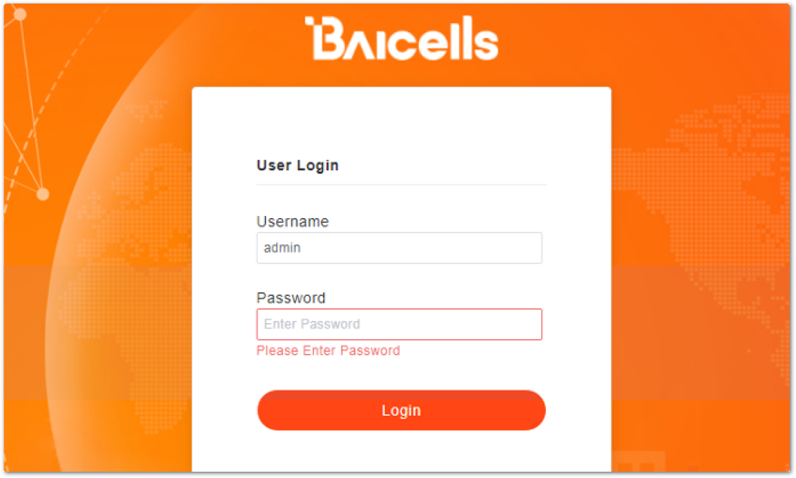 Figure 1: GUI Login Page
- Input your login credentials, and click Login.
- Default username: admin
- Default password: admin
For security reasons, you should change the default password after your first log in.
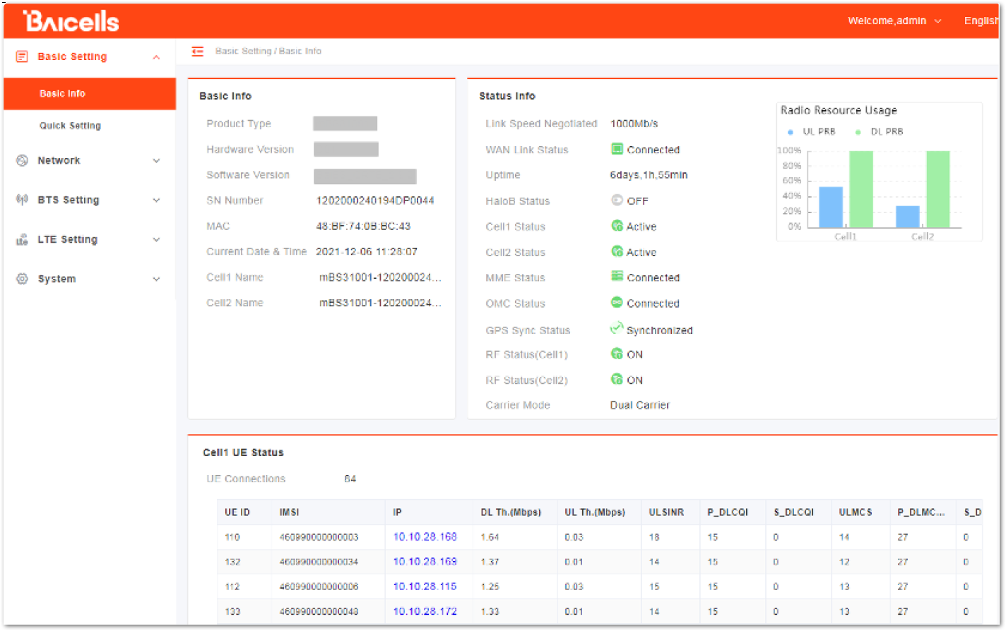 Figure 1: GUI Login Page
The information varies by product type or software version.
The homepage displays the navigation pane on the left and shows the window for the first menu: Basic Setting > Basic Info. This window is like a dashboard for the eNB, which includes three parts:
- Basic Info
- Status Info
- Cell UE Status
Basic Info The upper left of the window shows basic information such as the product type, hardware and software version, serial number, and MAC address.
Status Info The upper right of the window shows the following information:
- Status backhaul connectivity information (whether the cell is currently active or inactive)
- eNB connection to the MME in the core
- OMC connectivity
- IPsec tunnel connection
- Synchronization status
- Carrier Mode
- Radio Resource Usage
Cell UE Status The lower half of the window shows the connected UE quantity and its details, including the following:
- UE ID
- IMSI
- IP
- Port
- DL/UL Throughput
- UL SINR
On the top right corner of the window, there is the system operation menu. Click the drop-down arrow to expand and show the functionalities such as Reboot, Change Password, and Logout functions.
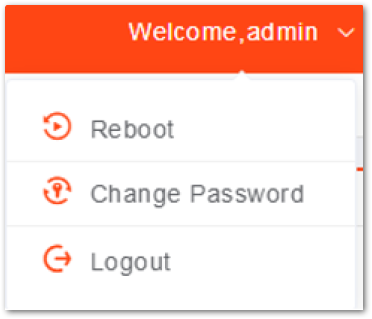 Figure 1: System Menu
Quick Setting Parameters
The Quick Settings determine important RF parameters. If the eNB operates in CBRS mode, it also determines SAS parameters. These parameters need to be planned during the network planning stage.
Quick Setting Overview
In the navigation column on the left, select Basic Setting then Quick Setting to enter the Quick Setting page.
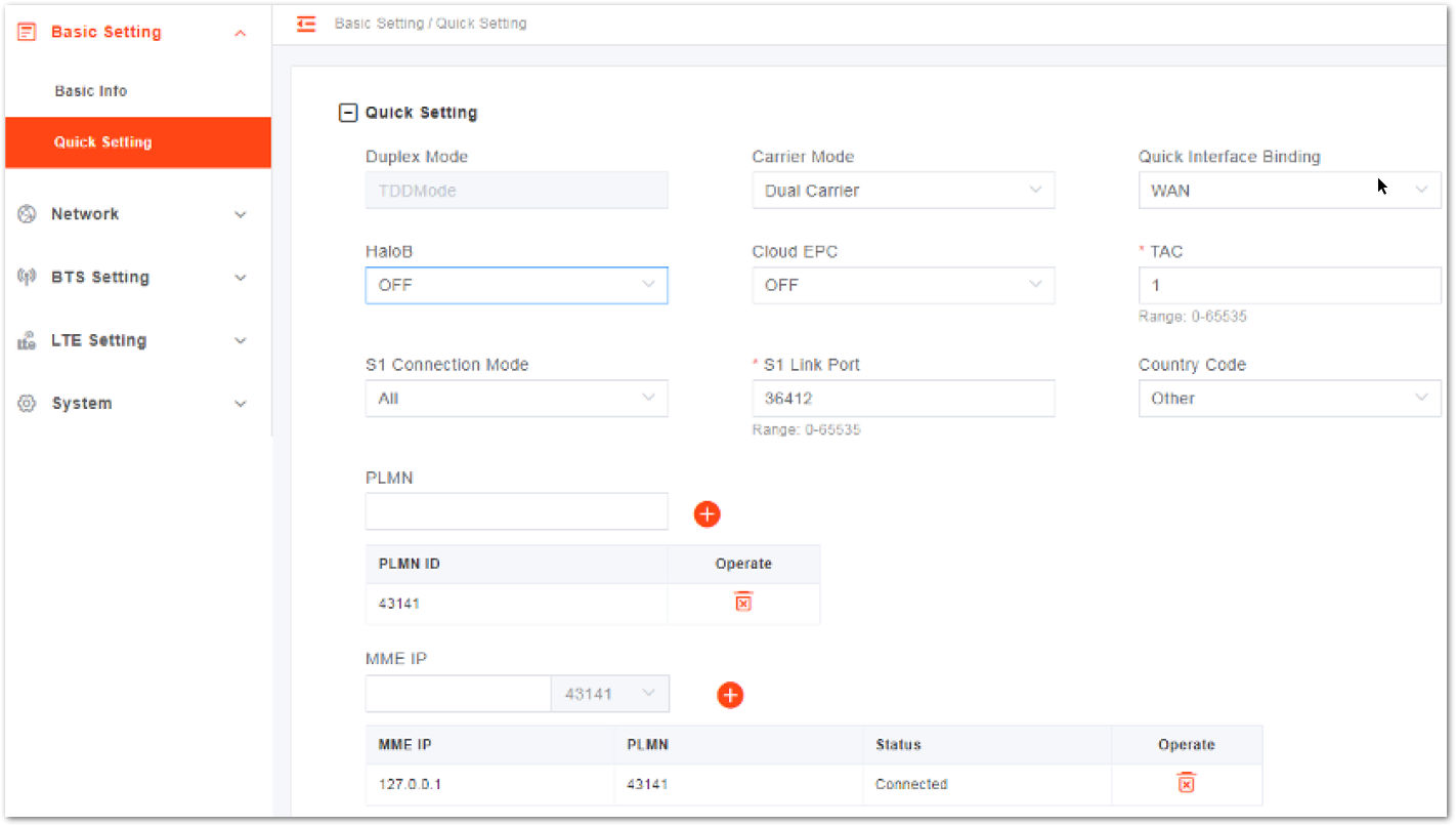 Figure 1: Quick Setting Page
Table 2: Quick Setting Parameter Description
| Parameter | Description |
|---|---|
| Duplex Mode | The system presets the parameter to the TDD mode automatically. |
| Carrier Mode | The carrier mode eNB supports. •Single Carrier - supported. The eNB only supports one cell in the single carrier mode. •Dual Carrier - not supported •Carrier Aggregation - not supported |
| Quick Interface Binding | •Assign the interface connected to the MME. •Select an interface from the network interfaces that are already configured in WAN/VLAN. The WAN interface is used by default, but the VLAN interface can also be used. |
| TAC | Tracking Area Code (TAC) of the cell site where the eNB resides. It is used to determine the range of the paging information. |
| S1 Connection Mode | The connection mode of the S1 interface between the eNB and the core network. •One: The eNB will connect only to the first MME. •All: The eNB will connect to all MMEs configured. |
| S1 Link Port | The port of S1 link used. |
| Country Code | Select whether the eNB operates in CBRS mode. •USA-FCC (CBRS): operating in CBRS mode. •Other: operating in normal mode. |
| PLMN | The numerical identifier for the operator's Public Land Mobile Network (PLMN) for this cell. It must be a 5 or 6-digit number. When the PLMN ID is added, it will display in the PLMN list. |
| MME IP | IP address of the cell’s associated MME, identical to the IP address of the MME at the core network side. The IP address of MME is configured in the Core Network. When the MME IP is added, it will display in the MME IP list. |
Cell Quick Setting
The cell quick setting includes the band, bandwidth, EARFCN, and frequency.
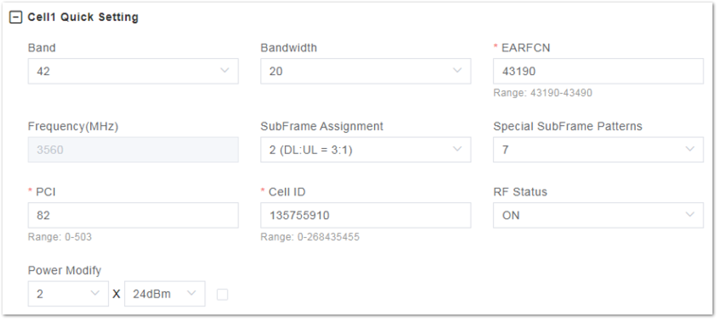 Figure 1: Cell Quick Setting Page
Table 3: Cell Quick Setting Parameters Descriptions
| Parameter | Description |
|---|---|
| Band | The system selects the operating frequency band automatically according to the hardware board type. If SAS is enabled, the SAS vendor will assign the band. |
| Bandwidth | Select the uplink and downlink bandwidth. •5 MHz •10 MHz •15 MHz •20 MHz |
| EARFCN | The absolute radio frequency channel number, selected by the operator. Allocated by the operator. |
| Frequency (MHz) | The eNB’s operating frequency, selected by the operator. The range depends on the base station model and country code. |
| SubFrame Assignment | Downlink (DL) and uplink (UL) subframe configuration. •1 (DL: UL=2:2) transmission ratio •2 (DL: UL=3:1) transmission ratio (default) •6 (DL: UL=3:5) transmission ratio |
| Special SubFrame Patterns | This is a standard LTE setting that pertains to synchronization of downlink and uplink timing. The guard period between switching from DL to UL or UL to DL determines the maximum supportable cell size. The guard period must be large enough to cover the propagation delay of DL interferers. •Range: 5 or 7 •Default: 7 |
| PCI | Physical Cell ID (PCI) is allocated by the operator. PCI is an essential Layer 1 cell identity for each cell site in the network. Planning PCIs is crucial for QoS. Range: 0 to 503 RAKwireless does not use and does not work with PCI 0. ::: |
| Cell ID | Unique identification number for the Cell ID. Range: 0 to 268,435,455 |
| RF Status | Enable/disable the radio frequency emissions of the eNB. The default value is enabled. If the RF status is set to be disabled, the eNB is no longer transmitting or receiving signals. |
| Power Modify | The maximum output power on each port. Must be within regulatory guidelines for the region. This field may be used in situations where you need to reduce the output power, such as testing the eNB before installing it on a tower. Restricting the eNB output to reduce interference with other eNBs in the same geographical area or staying within Effective Isotropic Radiated Power (EIRP) rules. If the check box on the right is selected, you can configure any power. |
SAS Setting
If the Country Code is set to USA-FCC (CBRS), the Spectrum Access System (SAS) parameters will display and must be configured.
The SAS is responsible for the management of the Citizens Broadband Radio Service Device (CBRD) and spectrum assignment. The registration, authentication, spectrum assignment and power of the CBRD is determined by SAS. Therefore, when the eNB needs to access into a CBRS system, it will connect to the SAS and report parameters to the SAS.
- Configure the general parameters.
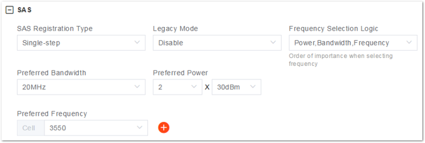 Figure 1: SAS General Parameter
Table 4: SAS General Parameters Descriptions
| Parameter | Description |
|---|---|
| SAS Registration Type | The registration mode. •Single-step •Multi-step |
| Legacy Mode | Enable or disable legacy mode. |
| Frequency Selection Logic | The sequence of importance of power, bandwidth, and frequency. |
| Preferred Bandwidth | The preferred bandwidth. |
| Preferred Power | The preferred transmit power. The maximum can be set to the maximum transmitting power supported by the eNB at increments of 1. |
| Preferred Frequency | The preferred frequency of the cell. |
- Different parameters will be configured based on the value of SAS Registration Type.
- If some information has been stored in SAS, set SAS Registration Type to Multi-step.
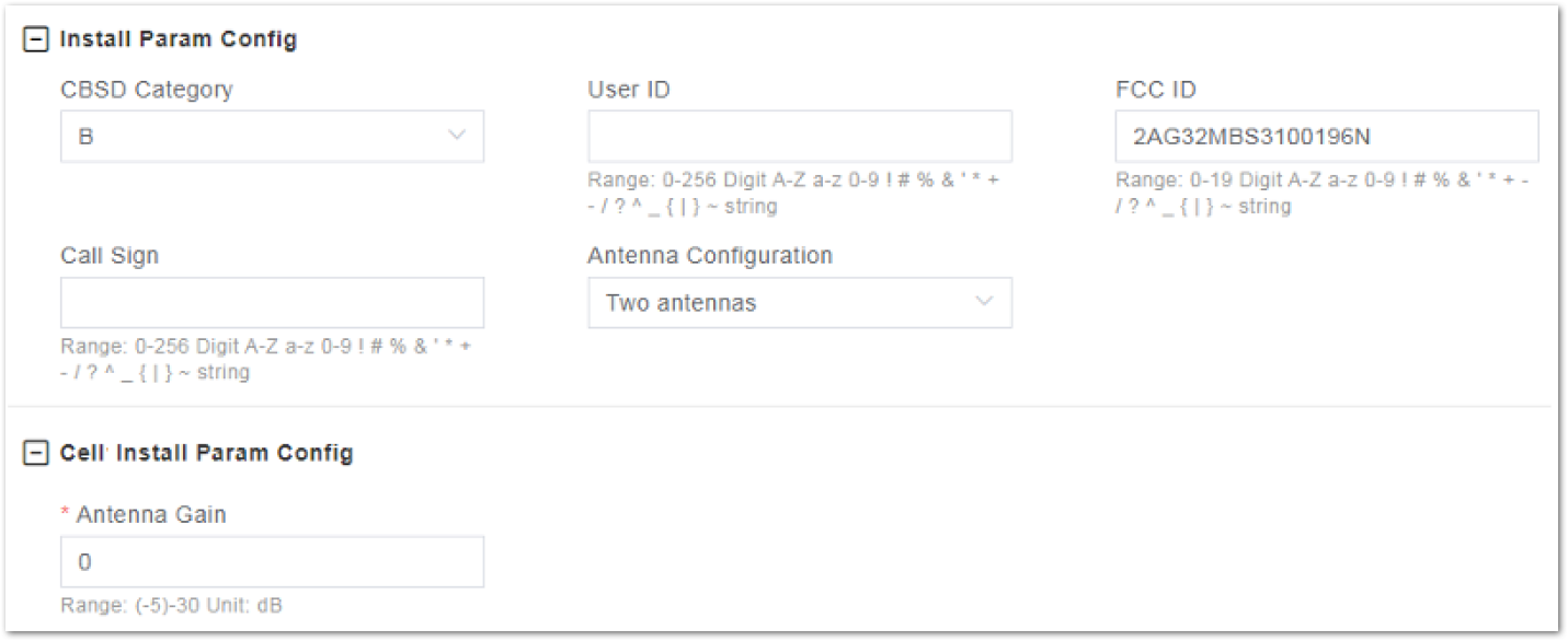 Figure 1: SAS Multi-Step Mode
Table 5: Multi-Step Antenna Installation Parameter Descriptions
| Parameter | Description |
|---|---|
| CBSD Category | The type of the eNB: •A: home eNB •B: macro eNB |
| User ID | Registered SAS user ID |
| FCC ID | Registered FCC ID |
| Call Sign | Calling signal |
| Antenna Configuration | If the eNB works in dual carrier mode, select one or two antennas. |
| Antenna Gain | The antenna gain of the cell |
- If no eNB information is stored in SAS, set SAS Registration Type to Single-step.
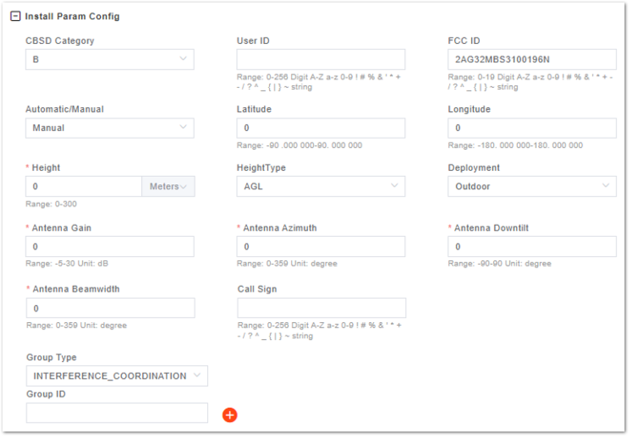 Figure 1: SAS Single-Step Mode
Table 6: Single-Step Antenna Installation Parameter Descriptions
| Parameter | Description |
|---|---|
| CBSD Category | The type of the eNB: •A: home eNB •B: macro eNB |
| User ID | User ID |
| FCC ID | FCC ID |
| Automatic/Manual | •Automatic: Automatically obtain the geographical location of the eNB, including longitude, latitude, height, and height type. •Manual: Manually input the longitude, latitude, height, and height type of the eNB. |
| Latitude | The latitude of eNB, which is acquired automatically. |
| Longitude | The longitude of eNodeB, which is acquired automatically. |
| Height | The height of the eNB |
| Height Type | The height type is AGL and AMSL. |
| Deployment | Select the eNB deployment location. •Indoor •Outdoor |
| Call Sign | Calling signal |
| Antenna Configuration | If the eNB works in dual carrier mode, select one or two antennas. |
| Group Type | The group type |
| Group ID | The group ID |
| Antenna Gain | The antenna gain of the eNB |
| Antenna Azimuth | The azimuth of the antenna |
| Antenna Down tilt | The down tilt of the antenna |
| Antenna Beamwidth | The beamwidth of the antenna |
| CPI ID | CPI ID |
| CPI Name | CPI name |
| Install Cert Time | The certification time of the CPI |
- In the single-step mode, CPI parameters should be configured.
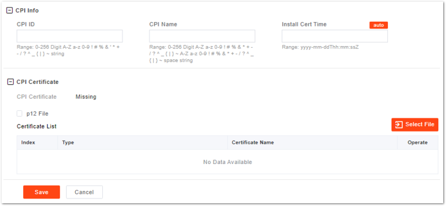 Figure 1: CPI Information
Table 7: Single-Step CPI Information Parameter Descriptions
| Parameter | Description |
|---|---|
| CPI ID | CPI ID |
| CPI Name | CPI name |
| Install Cert Time | The certification time of the CPI |
- After setting the above parameters, click Select File to import the CPI certificate. If the CPI certificate is a
p12file, enter the password. - Click Save to complete the SAS setting.
Network Interface Configuration
Network interface configuration includes the following:
- WAN
- VLAN
- IPsec
- LAN
- static routes
The LAN interface is the internal maintenance interface used in initialization and will no longer be needed in normal operation. The WAN interface is an external communication portal (Internet connection) to the eNB’s NMS and the MME. The only option for the Interface name field is WAN. The WAN interface supports the configuration of multiple VLANs.
The IP address of the WAN interface and the LAN interface cannot be in the same network segment.
WAN/VLAN Configuration
- To enter the WAN interface configuration page, select Network, then click WAN/LAN/VLAN.
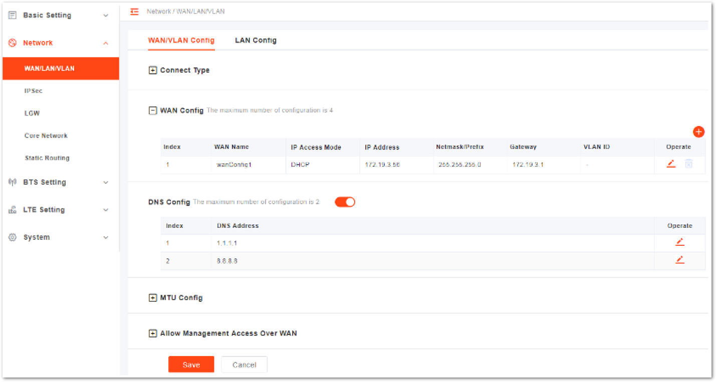 Figure 1: WAN/VLAN Configuration
The configuration page is divided into five parts:
- Connect Type
- WAN Config
- DNS Config
- MTU Config
- Allow Management Access Over WAN
- Select Connection Type.
- Copper: RJ-45 electrical interface
- Fiber: Optical fiber interface
The value is based on the eNB model. If the eNB does not support optical ports, the value must be set to Copper.
- Configure WAN interface, with up to four (4) supported WANs. Open the configuration window by clicking the drop-down arrow and entering the WAN configuration parameters.
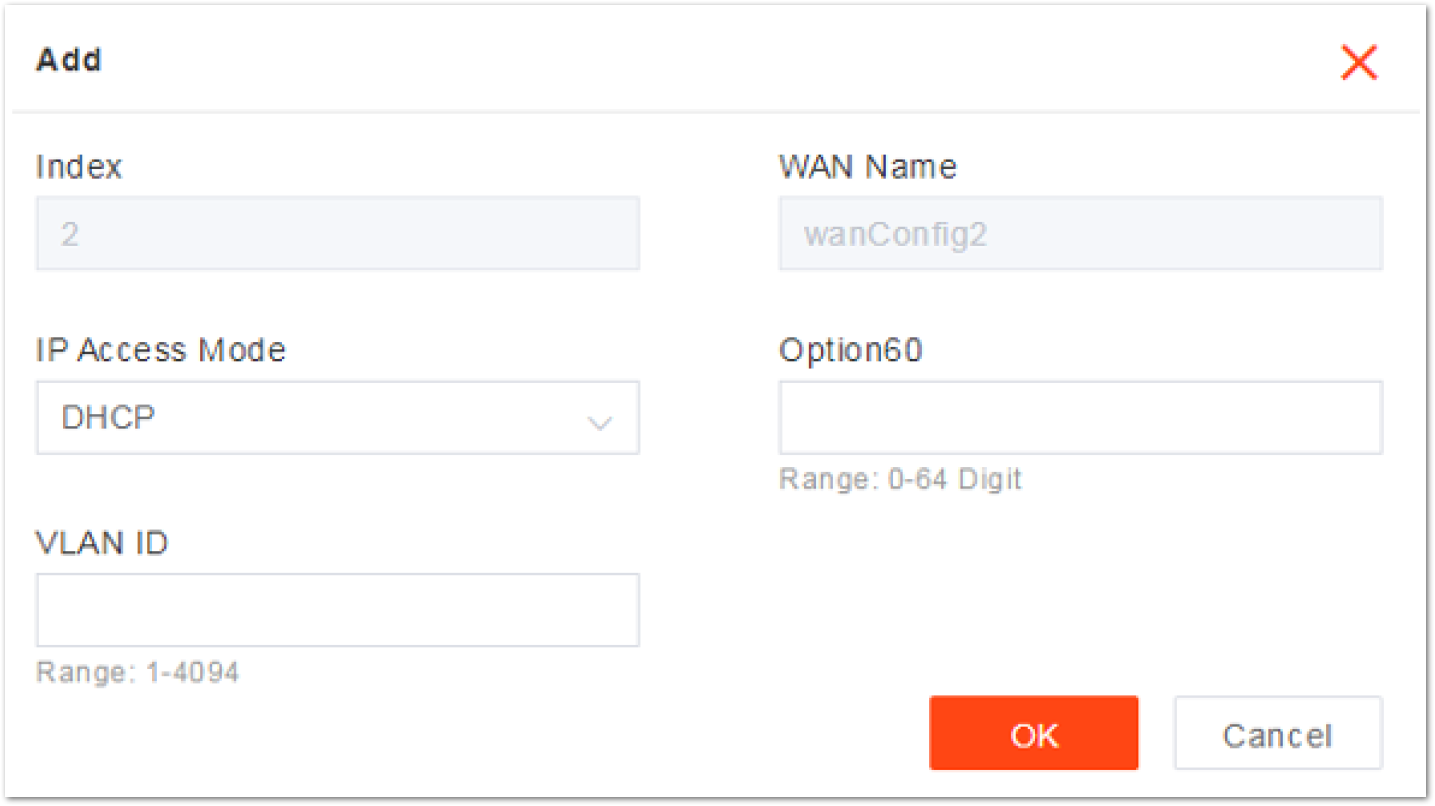 Figure 1: Configure WAN Interface
Table 8: WAN Configuration Parameters
| Parameter | Description |
|---|---|
| Index | The index is generated automatically. |
| WAN Name | The WAN name is generated automatically. |
| IP Access Mode | The interface protocol used by the WAN interface acquired includes: •DHCP: If DHCP is selected, only the option 60 parameter needs to be configured. •Static IP •IPv6 DHCP •IPv6 Static IP |
| Current IP | IP address of the WAN interface. If DHCP is selected, the IP address is acquired automatically. |
| option60 | If set IP Access Mode, display this parameter. It is an identity to match with terminals to differentiate different terminals. |
| Netmask | If the IP Access Mode is set to Static IP, display this parameter. Subnet mask address of the IP address. |
| Gateway | If the IP Access Mode is set to Static IP, enter the gateway address. IP address of the default gateway. |
| Prefix | If the IP Access Mode is set to IPV6 Static IP, display this parameter. Prefix of IPv6 address for the WAN interface. |
| IPv6 Gateway | If the IP Access Mode is set to IPV6 Static IP, display this parameter. The gateway of IPv6 address for the WAN interface. |
| VLAN ID | When the operator needs to transmit data of different types through separate channels, configure more IP addresses for WAN interface through VLAN, and assign them different VLAN IDs. |
- When enabling DNS, move the slider to the right first with up to two DNS supported. Then, click the drop-down arrow to enter the DNS edit window.
 Figure 1: DNS Configuration
Table 9: DNS Configuration Parameters
| Parameter | Description |
|---|---|
| Index | Automatically generated |
| DNS Address | The IP address of the DNS |
- Configure the maximum transmission unit (MTU), with a default value of 1500 bytes.
Setting the right MTU for the network can help to improve the transmission efficiency.
- Select the enable or disable function that access the LMT through WAN interface for management. If this parameter is set to enable, the administrator can maintain the eNB through the WAN interface.
- To complete the WAN interface configuration, click Save.
LAN Configuration
The Local Network/LAN fields are used to configure the Local Maintenance Terminal (LMT) port on the eNB. During the initial eNB setup and configuration, the port can be used, with a default IP address of the LAN interface of 192.168.150.1. In general, the initial value need not be changed.
- To enter the LAN interface configuration page, select LAN Config.
 Figure 1: LAN Configuration
- The LAN interface is enabled by default. If the IP Address and Subnet Mask need to be changed, input the new values.
- To complete the modification on the LAN interface, click Save.
If the IP address of the LAN interface is modified, the eNB must be rebooted to take effect. Then, log in to the client using the new IP address.
IPsec Configuration
The security gateway (SeGW) can provide a security protocol at the network layer to ensure safe message transmission. If the operator has deployed the security gateway, the eNB needs to enable the IPsec function accordingly to establish a safe VPN channel between the eNB and the SeGW.
With up to two IPsec tunnels are supported, the eNB disables the IPsec by default.
- To enter the IPsec configuration page, select Network and choose IPsec Config tab.
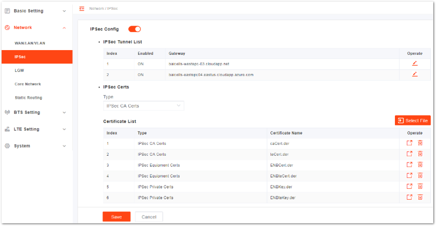 Figure 1: IPsec Configuration
- Select the enable or disable IPsec function. The IPsec function is enabled by default.
- In the IPsec Tunnel List area, click the edit icon to display the IPsec tunnel configuration page. Then, configure the basic parameters of IPsec tunnel mode.
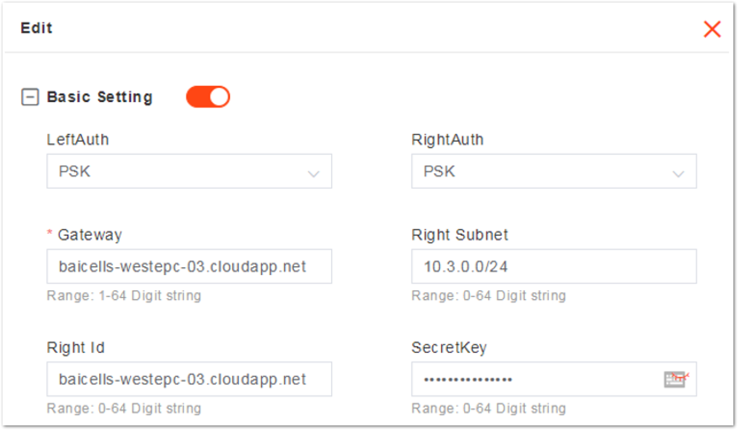 Figure 1: Basic Setting of IPsec Tunnel Mode
Table 10: Basic IPsec Tunnel Mode Parameter Descriptions
| Parameter | Description |
|---|---|
| LeftAuth | Local authentication type of the IPsec. Must be consistent with the security gateway side. •PSK •PUBKEY NOTE: It is not recommended to change this value. |
| RightAuth | Peer authentication type of the IPsec. Must be consistent with the security gateway side. •PSK •PUBKEY WARNING It is not recommended to change this value! |
| Gateway | The security gateway (IPsec server) IP address. Make sure the IP address entered on this field matches the actual IP address on the security gateway side. |
| Right Subnet | IP address of the remote subnet, which must be consistent with the security gateway side. Messages within this address range will be packed as a tunnel. |
| Right Id | Identification of the server end (0-48 digit string). It must be consistent with the security gateway side. If there is no security gateway right identifier, leave this field empty. |
| SecretKey | File name of the private key. When the auth is set to psk, the value is the password of authentication. |
The Advanced Setting fields is particularly important to network operations as areas become denser with users. However, it is highly recommended to use default values for the Advanced Setting fields. Improper changes may lead to system malfunctions.
- In the Advance Setting area, click the plus sign and enter the advanced setting page.
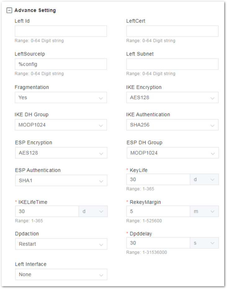 Figure 1: Advanced Setting of IPsec Tunnel Mode
Table 11 : Advanced IPsec Tunnel Mode Parameter Description
| Parameter | Description |
|---|---|
| Left Id | Identification of the client end (0-48 digit string). It must be consistent with the security gateway side. If there is no security gateway left identifier, leave this field empty. |
| LeftCert | If set left Auth to pubkey, the parameter needs to be set. For Certificate name, the version is clientCert.derpsk. |
| LeftSourceIp | Virtual address allocation assigned by the system. If absent, use the local IP address. |
| Left Subnet | IP address of the local subnet |
| Fragmentation | Types of fragmentation: •YES •ACCEPT •FORCE •NO |
| IKE Encryption | Internet Key Exchange (IKE) encryption method is a protocol used to ensure security for virtual private network (VPN) negotiation and remote host or network access. •AES128 •AES256 •3DES •DES |
| IKE DH Group | IKE Diffie-Hellman (DF) key computation or exponential key agreement - to be used between two entities. •MODP768 •MODP1024 •MODP1536 •MODP2048 •MODP4096 |
| IKE Authentication | Authentication algorithm •SHA1 •SHA1_160 •SHA256_96 •SHA256 |
| ESP Encryption | Encapsulating Security Payload (ESP) is a member of the IPsec protocol suite that provides origin authenticity, integrity, and confidentiality protection of packets. •AES128 •AES256 •3DES •DES |
| ESP DH Group | ESP Diffie-Hellman (DF) key computation or exponential key agreement - to be used between two entities. •MODP768 •MODP1024 •MODP1536 •MODP2048 •MODP4096 |
| ESP Authentication | ESP Authentication algorithm: •SHA1 •SHA1_160 •SHA256_96 •SHA256 |
| Key Life | IPsec security association (SA) renegotiation time. Format: Seconds, Minutes, Hours, or Days |
| IKELifetime | IKE security association renegotiation time. Format: Seconds, Minutes, Hours, or Days |
| RekeyMargin | Renegotiation time before the expiration of the IKE lifetime (negotiate the IKE security association time before the expiration of the IKE life time). Format: Seconds, Minutes, Hours, or Days |
| Dpdaction | DPD stands for dead peer detection (DPD) protocol. It determines what action to take when a gateway exception occurs. •None •Clear •Hold •Restart |
| Dpddelay | Time interval for sending the DPD detection message. Format: Seconds, Minutes, Hours, or Days |
| Left Interface | The interface on the eNB side |
- In IPsec Certs area, manage the IPsec certificates.
- Select the type of IPsec certificate, including three types:
- IPsec CA Certs: ROOT certificate
- IPsec Equipment Certs: Certificate of server and client
- IPsec Private Certs: Private key of the server and client
- Click Select File to upload the corresponding IPsec certificate file.
- Click Save to complete the IPsec configuration.
Core Network
In the left navigation column, select Network and then Core Network to enter the core network parameter configuration page.
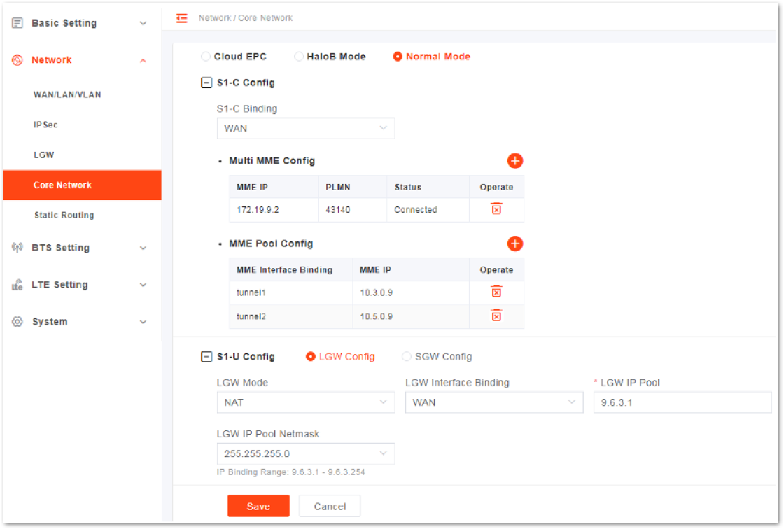 Figure 1: Core Network Setting Normal Mode
The core network configuration includes S1-C control plane and S1-U user plane configuration.
S1-C Config
- Select the interface binding with S1-C plane, which has been configured in WAN/VLAN.
- In the Multi MME configuration list, click the plus sign to show the multi-MME configuration window.
 Figure 1: Multi-MME Configuration
PLMN and MME IP can also be configured in the Quick Setting Parameters section.
- Select PLMN from the drop-down list.
- Input the corresponding MME IP address.
- In the MME pool configuration list, click the plus sign to show the MME interface binding window.
 Figure 1: MME Interface Binding
- Select the MME IP address for the two IPsec tunnels separately.
- If the MME IP address needs to be modified, delete the binding, and add it again.
S1-U Config
Select the SGW binding interface from the drop-down list, which has been configured in the WAN/VLAN.
Static Routing Configuration
- To enter the static route configuration page, select Network then Static Routing.
 Figure 1: MME Interface Binding
- Click the plus sign to display static configuration parameters
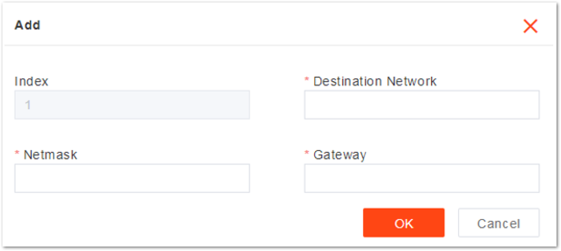 Figure 1: Add a Static Route
- Input the static route configuration parameters, described in the Static Route Parameter Description table.
Table 12 : Static Route Parameter Description
| Parameter | Description |
|---|---|
| Index | The index of the static route. Assigned automatically. |
| Destination Network | The destination IP address. NOTE: |
| The destination IP address must be reachable from the original IP address of the WAN interface or VLAN source port. | |
| Netmask | The subnet mask of the destination IP address. |
| Gateway | The gateway IP address of the target IP address. |
- Click Save to complete the static route configuration.
- The system supports the configuration of up to four static routes. Click the Validated Route List tab to view the route table.
Base Transceiver Station (BTS) Setting
The base transceiver station (BTS), or base station, settings are related to security, management, and synchronization with other network elements.
eNB Name Setting
- On the left navigation column, select BTS Setting > eNodeB Setting to enter the eNB setting page.
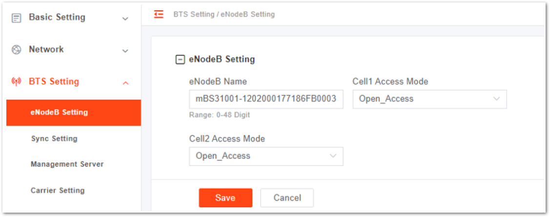 Figure 1: eNB Name Setting
-
Type in the eNB Name and select the Cell1/Cell2 Access Mode.
- Open_Access
- Closed_Access
- Hybrid_Access
-
If Closed_Access or Hybrid_Access is selected, the Closed Subscriber Group (CSG) parameters display.
Table 13: Closed Subscriber Group Parameter Description
| Parameter | Description |
|---|---|
| CSG ID | CSG ID |
| CSG Start PCI | The start of the CSG. Range is from 0 to 503. |
| CSG PCI Range | The PCI range of the CSG. Range is from 0 to 15. |
- Click Save to complete the eNB name setting.
Synchronization
LTE technology standards specify timing and synchronization requirements between adjacent eNBs. Synchronized transmissions help to avoid eNBs interfering with one another, optimize bandwidth usage, and enhance network capacity.
Table 14: Synchronization Sources
| Parameter | Description |
|---|---|
| NTP | Network Time Protocol |
| PTP | Precision Timing Protocol, compliant with IEEE1588 protocol. |
| GNSS | Only GPS is supported. |
| NL | Network Listening |
| EXT_CLK | External Clock |
| EXT_PPS | Pulse Per Second Synchronization |
| FREE_RUNNING | If there is no synchronization resource, select free running mode. |
In the left navigation column, select BTS Setting then Sync Setting to enter the synchronization configuration page.
NTP Synchronization
- When Sync Mode is set to NTP, configure the NTP server following the NTP section.
 Figure 1: NTP Synchronization Setting
PTP Synchronization
- PTP synchronization is also known as 1588v2 synchronization. Refer to Table 15 for the parameter description.
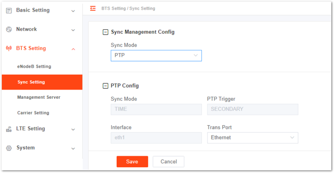 Figure 1: PTP (1588v2) Parameter Description
Table 15: PTP (1588v2) Parameter Description
| Parameter | Description |
|---|---|
| Sync Mode | The current synchronization mode is Time, which is set by the system. |
| PTP Trigger | The current synchronization mode is SECONDARY, which is set by the system. |
| Interface | The current synchronization mode is eth1, which is set by the system. |
| Transport | Transport protocol: •Ethernet •UDP |
GNSS Synchronization
- For GNSS synchronization, it displays the number of satellites as well as longitude and latitude.
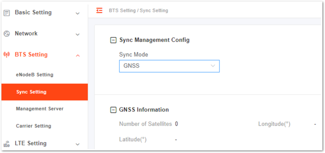 Figure 1: GNSS Synchronization Setting
NL Synchronization
- NL Synchronization includes two (2) modes: Regular Mode and Full Band Scan.
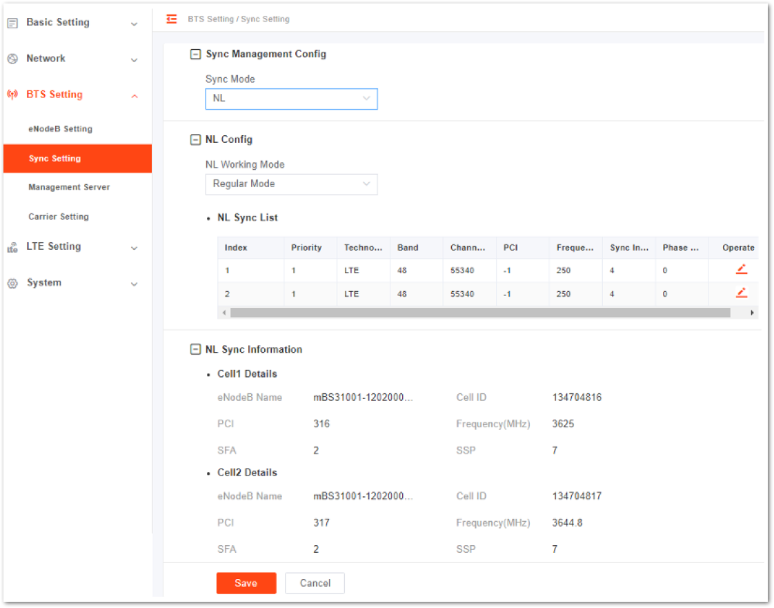 Figure 1: NL (Regular Mode) Synchronization Setting
To edit air interface synchronization list, click the Edit button.
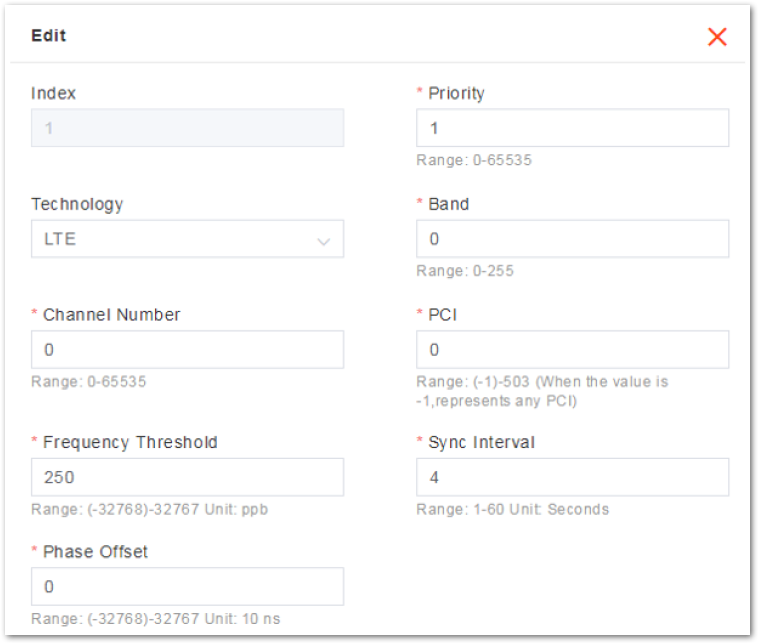 Figure 1: NL Sync Parameters – Regular Mode
Table 16: NL Synchronization Parameter Description – Regular Mode
| Parameter | Description |
|---|---|
| Index | The index is generated automatically. |
| Priority | The priority of this synchronizing source. |
| Technology | Network mode. Only LTE is supported. |
| Band | The frequency of the synchronizing band. |
| Channel Number | The frequency point of the synchronizing band. |
| PCI | The PCI of the synchronizing band. |
| FreqUncertainty Threshold | The frequency threshold of the synchronizing band. |
| Sync Interval | Interval of synchronizing measurement. |
| Phase Offset | Phase offset |
In the full scan mode, the eNB scans the frequency within the specified range.
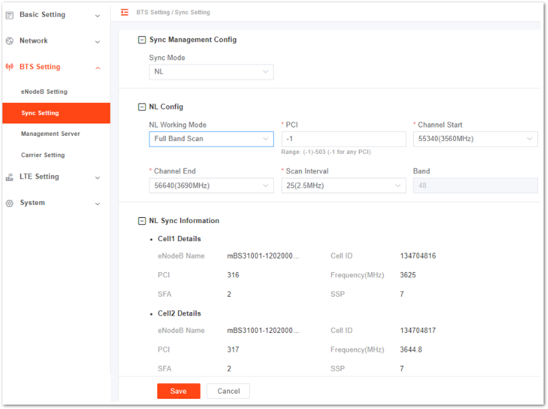 Figure 1: NL Synchronization Setting – Full Scan Mode
 Table 17: NL Synchronization Parameter Description – Full Scan Mode
| Parameter | Description |
|---|---|
| Index | The index is generated automatically. |
| Priority | The priority of this synchronizing source |
| Technology | Network mode. Only LTE is supported. |
| Band | The frequency of the synchronizing band |
| Channel Number | The frequency point of the synchronizing band |
| PCI | The PCI of the synchronizing band |
| Frequency Threshold | The frequency threshold of the synchronizing band |
| Sync Interval | Interval of synchronizing measurement |
| Phase Offset | Phase offset |
FREE_RUNNING/EXT_CLK/EXT_PPS
- When Sync Mode is set to FREE_RUNNING, EXT_CLK, or EXT_PPS, no other parameters are configured.
 Figure 1: Synchronization Setting –FREE_RUNNING/EXT_CLK/EXT_PPS
There is no need to connect any clock source when using FREE_RUNNING, as its crystal oscillator provides a synchronous clock. If you choose EXT_CLK or EXT_PPS, connect to an external clock source.
Management Server
For the Network Management System (NMS), an operator has the option to use their own management server.
After configuring NMS, you can log in to NMS to check whether the eNBs have been added or not. Once added, the eNB can be configured and managed on the NMS.
- In the left navigation column, select BTS settings then Management Server.
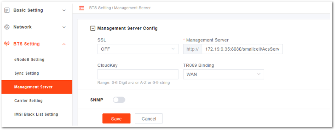 Figure 1: Configure Network Management Server
- Input the network management parameters. Refer to Table 18 for the parameter description.
Table 17: Network Management Server Parameter Description
| Parameter | Description |
|---|---|
| SSL | •Enable or disable the SSL. •If the SSL is enabled, the eNB connects to the OMC via https and the management server address starts with https. |
| Management Server | •IP address and port number of the NMS •When the NMS is hosted in the cloud, the domain name is also supported. |
| CloudKey | •The NMS assigns a unique cloud key for each operator. •When the eNB is registered to the NMS, the eNodeB can be identified by NMS. The default factory setting of Cloud Key is none. When the eNB is registered to the NMS, it is assigned to the default group. The administrator needs to move the eNB to an operator. If the value of Cloud Key is set to an invalid value, the NMS will deny the eNB access. |
| TR069 Binding | The interface binding with the TR069 protocol |
- If the eNB will report KPI information to the third-party NMS, enable the SNMP function.
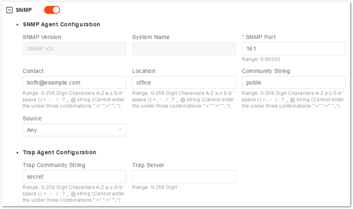 Figure 1: SNMP Configuration
Table 18: SNMP Configuration Parameter Description
| Category | Parameter Name | Description |
|---|---|---|
| SNMP Agent | SNMP Version | The current supported SNMP version is SNMPv2c. |
| System Name | The name of the community. | |
| SNMP Port | The port of SNMP protocol used. | |
| Contact | Contact e-mail. | |
| Location | The location of the system. | |
| Community String | Define a community, default is public. | |
| Source | The source address for acquiring information. | |
| Trap Agent | Trap Community String | Define a community; default is secret. |
| Trap Server | The IP address of host. |
- Click Save to complete the NMS and SNMP configuration.
Carrier Mode
The eNB supports single carrier only.
- In the left navigation column, select BTS Settings then Carrier Setting to enter the carrier mode configuration page.
 Figure 1: SNMP Configuration
- Select a carrier mode:
- Single Carrier: In single carrier mode, the eNB supports only one cell.
- Dual Carrier: NOT Supported
- Carrier Aggregation: NOT Supported
- Click Save to complete the carrier mode setting.
LTE Setting
It is not recommended to modify the advanced LTE parameters for common operators. It is better to keep the default values. For senior experts in need, proceed with extreme caution.
The LTE menu comprises various sub-menus that contain mobility and other radio-related settings. Efficient wireless network operations depend on several important LTE parameters.
When configuring an intra-frequency cell, you only need to configure the neighboring cell. However, when configuring an inter-frequency cell, you should first configure the neighbor frequency and then configure the neighbor cell.
Configure LTE Neighbor Frequency and Cell
- To enter the LTE neighbor frequency and cell configuration page, go to LTE Setting and select LTE Freq/Cell.
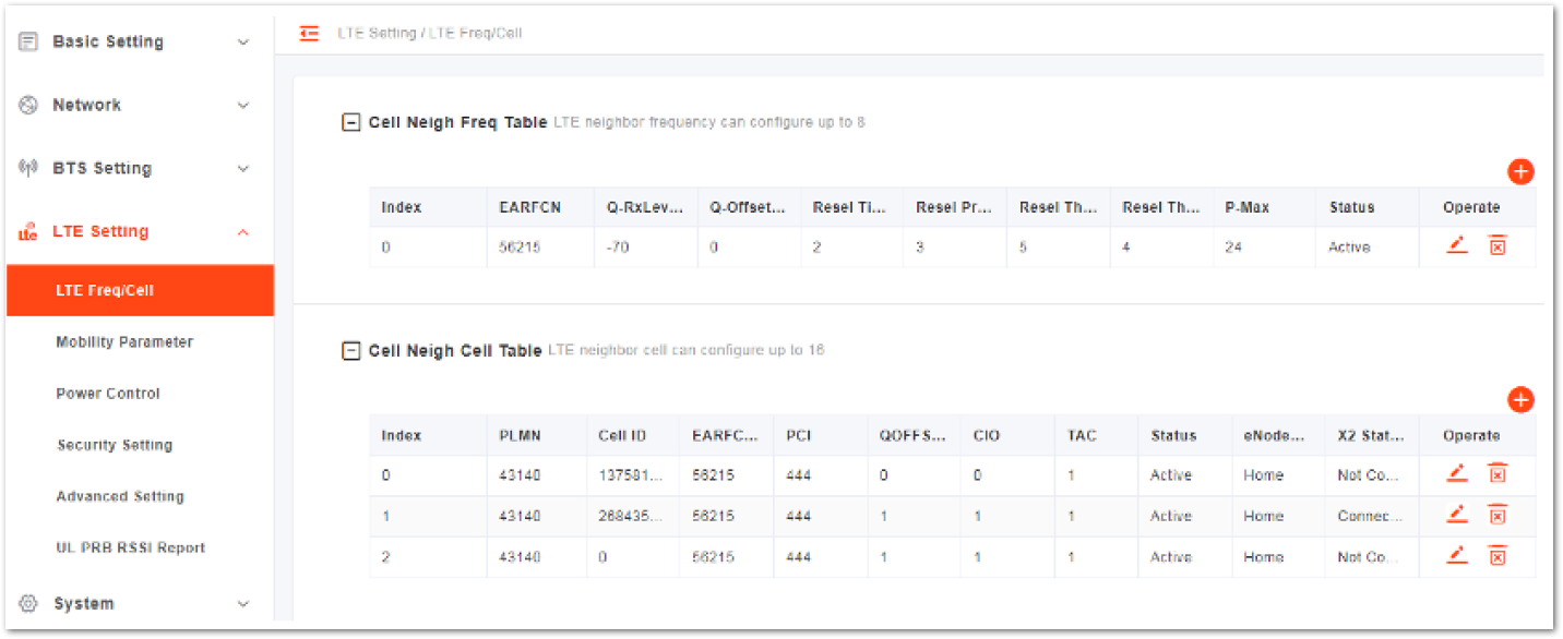 Figure 1: LTE Neighbor Frequency/Cell Settings
- Users can add, modify, and delete the LTE neighbor frequency and cell. Up to eight (8) LTE neighbor frequencies and 16 LTE neighbor cells can be set.
When the eNB operates in dual carrier mode, the LTE neighbor frequency and cell should be separately configured for cell1 and cell2.
LTE Neighbor Frequency
- In the neighbor frequency list, click the plus button to enter the page for adding an LTE neighbor frequency.
Table 18: LTE Neighbor Frequency Parameter Description
| Parameter | Description |
|---|---|
| EARFCN |
|
| Q-RxLevMin |
|
| Q-OffsetRange |
|
| Resel Timer |
|
| Resel Prior |
|
| Resel Thresh High |
|
| Resel Thresh Low |
|
| P-Max |
|
- To complete the LTE neighbor frequency setting, click Save.
LTE Neighbor Cell
- In the Neighbor Cell List, click the plus button to enter the page for adding a LTE neighbor cell.
Table 19: LTE Neighbor Cell Parameter Description
| Parameter | Description |
|---|---|
| PLMN | The 5-6 digit PLMN that the neighbor cell belongs to. |
| Cell ID | Unique identification number for the cell. |
| EARFCN | Frequency point of the neighbor cell. |
| PCI | Physical Cell Identifier (PCI) of the neighbor cell. |
| QOFFSET | Frequency offset of this neighbor cell. Indicates the difference in signal level between the serving and this neighboring eNB, as determined by the received signal level at the UE. If the received signal level is better from a neighboring eNB by at least this amount of difference in dB, the UE will reselect this cell. Range is +24 to -24. A typical value is 0 dB. |
| CIO | Cell Individual Offset (CIO) is this neighbor eNB’s cell offset, which is one of the variables used to determine which eNB will best serve a given UE. Range is +24 to -24. A typical value is 0 dB. |
| TAC | Tracking Area Code (TAC) of this neighbor cell |
| eNodeB | Type The type of the eNB: •Macro: the eNB is covering a large cell area and the transmission power is on the higher end of the power range. •Home: the eNB’s transmission power is much lower than Macro and covers a much smaller area. |
- To complete the LTE neighbor cells setting, click Save.
Mobility Parameter
The Mobility Parameter menu pertains to how roaming UE sessions are handled between different eNBs in the same service area. When a UE is connected to an eNB, that eNB becomes the serving eNB or cell, while other eNBs in the vicinity are called neighbor or target eNBs or cells.
The process of a device moving from cell to cell and changing over from its serving eNB to a neighbor (target) eNB is called handoff or handover. The UE communicates with its serving eNB to perform cell selection and reselection based on the parameters that you specify for each eNB.
On the left navigation column, select LTE Setting > Mobility Parameter to enter the mobility parameter configuration page.
When the eNB operates in dual carrier mode, the mobility parameters should be configured separately for cell1 and cell2.
A1 Event Threshold
The LTE A1 event is triggered when the serving cell’s Reference Signal Received Power (RSRP) is better than the A1 threshold. The A1 event can be used to turn off certain inter-cell measurements.
- Click A1 Event Threshold to display the A1 event threshold configuration parameter.
- Enter the value of LTE A1 RSRP Threshold.
- To complete the A1 event threshold setting, click Save.
A2 Event Threshold
The LTE A2 event is triggered when the serving cell’s RSRP is better than the A2 threshold.
- Click A2 Event Threshold to display the A2 event threshold configuration parameter.
- Enter the value of LTE A2 RSRP Threshold.
- To complete the A2 event threshold setting, click Save.
A3 Event Threshold
The LTE A3 event is triggered when the neighbor cell becomes better than the serving cell by as much as the offset value. The offset can be either positive or negative.
- Click A3 Event Threshold to display the A3 event threshold configuration parameters.
- Enter the value of Intra-Freq Handover A3 Offset.
- To complete the A3 event threshold setting, click Save.
A5 Event Threshold
The LTE A5 event is triggered when the serving cell becomes worse than Threshold 1 while a neighbor cell becomes better than Threshold 2. A5 event can control the edge of handover out of the serving cell and the edge of handover in of the neighbor cell.
- To display the A5 event threshold configuration parameters, click A5 Event Threshold
- Click Save to complete the A5 event threshold setting.
Table 20: A5 Event Threshold Parameter Description
| Parameter | Description |
|---|---|
| Intra-Freq/Inter-Freq Handover A5 RSRP Threshold1 | Intra frequency and inter frequency RSRP threshold parameter 1 of the A5 event. |
| Intra-Freq/Inter-Freq Handover A5 RSRP Threshold2 | Intra frequency and inter frequency RSRP threshold parameter 2 of the A5 event. |
Measurement Control Parameter
The Measurement Control parameters determine how frequently the UE measures the serving and neighboring eNB’s RSRP values and at what level of hysteresis-based RSRP triggers a handover. The UE evaluates the RF conditions around it and reports the information to the serving eNB. The eNB’s radio resource management function evaluates the measurements and determines whether or not to hand over the session to a neighbor eNB.
- To display the measurement control parameters configuration parameters, click Measurement Control Parameters.
- Click Save to complete the measurement control parameters setting.
Table 20: Measurement Control Parameter Description
| Parameter | Description |
|---|---|
| Hysteresis | •This parameter refers to the hysteresis (historical records) of the handover measurement event. •The value is used to avoid the frequent triggering of cell handover evaluation due to the fluctuation in wireless signals. This setting tells the UE, if you hear another eNB with at least this amount of dB or better, to initiate a handover. The lower the number the sooner the handover is initiated. If set too low, it may cause the UE to ping-pong between eNBs. •Range from 0 to 30 dB. The default is 0. In this example, the recommended value is 5 dB. |
| Time To Trigger | Length of time the target cell RSRP value is better than the serving cell before the UE initiates a handover request. |
Cell Selection Parameter
When the UE selects a PLMN, it will select an appropriate cell to residence.
- To display the cell selection parameters configuration parameters, click Cell Selection Parameter
- Click Save to complete the selection parameters setting.
Table 21: Cell Selection Parameter Description
| Parameter | Description |
|---|---|
| Qrxlevmin () | •The minimum acceptable signal level at the UE before cell selection. •Defining this parameter prevents the UE from accessing a cell with a low receiving signal level. The value of this parameter needs to take factors such as cell size, cell coverage, and background noise into consideration. •Reducing the parameter value will expand the allowable access range of the cell, but it may result in poor call quality. |
| QrxlevminOffset | •The minimum level offset (difference) in RSRP at the UE needed for cell selection. •When the UE residing on a VPLMN periodically searches for a higher-level cell, the minimum threshold value is offset to prevent ping-pong effect. |
Cell Reselection Parameter
When a UE is in idle state, it needs to select a better cell by monitoring the signal quality of the neighbor cell and the serving cell. Cell reselection includes the intra-frequency cell reselection and the inter-frequency cell reselection.
The intra-frequency cell reselection mainly solves the problem of wireless coverage. The inter-frequency cell reselection can solve the problem of wireless coverage, but also achieve load balancing between different frequency points.
- Click Cell Reselection Parameter to display the cell reselection parameters configuration parameters.
- Click Save to complete the cell reselection parameters setting.
Table 22: Cell Reselection Parameter Description
| Parameter | Description |
|---|---|
| S-IntraSearch | •Intra-frequency measurement threshold that must be met before the UE will reselect a neighbor eNB. •Range is 0 to 31 (integer). •In this example, the recommended value is 31 (integer), which means 31*2 = 62 dB. |
| S-NonIntraSearch | Inter-frequency measurement threshold that must be met before the UE will reselect a neighbor eNB. |
| Qrxlevmin() | •The minimum level for re-selection •Range is -70 to -22 (integer). •In this example, the recommended value is -62 (integer), which means -62*2 = -124 dB. |
| Qhyst | •Delay time for re-selection. Generally the value of the parameter is 2. •This parameter will overestimate the signal strength of the serving cell to delay the cell reselection. |
| Reselection Priority | •Priority for the reselection. •Range is 0 to 7. In this example, the recommended value is 4. |
| ThreshServingLow | Threshold for reselection to cells of lower priority. |
| Allowed Meas BW Sib3 | Measurement bandwidth allowed |
X2 Setting
- Select enable or disable X2 interface.
- Click Save to complete the X2 interface setting.
ANR Parameter
- To display the ANR configuration parameters, click ANR Parameter.
- Click Save to complete the ANR parameters setting.
Table 23: ANR Parameter Description
| Parameter | Description |
|---|---|
| Measurement Configuration | Select measurement mode •Measurement Disable •Intra Periodic •Intra A3 Event •Inter A5 Event |
| Intra-Freq ANR A3 Offset | If Measurement Configuration is set to Intra A3 Event, the parameter displays. The offset of A3 event. |
| Inter-Freq ANR A5 RSRP Threshold1 | If Measurement Configuration is set to Inter A5 Event, the parameter displays. The RSRP threshold1 of A5 event. |
| Inter-Freq ANR A5 RSRP Threshold2 | If Measurement Configuration is set to Inter A5 Event, the parameter displays. The RSRP threshold2 of A5 event. |
Power Control
On the left navigation column, select LTE Setting > Power Control to enter the power control parameter configuration page.
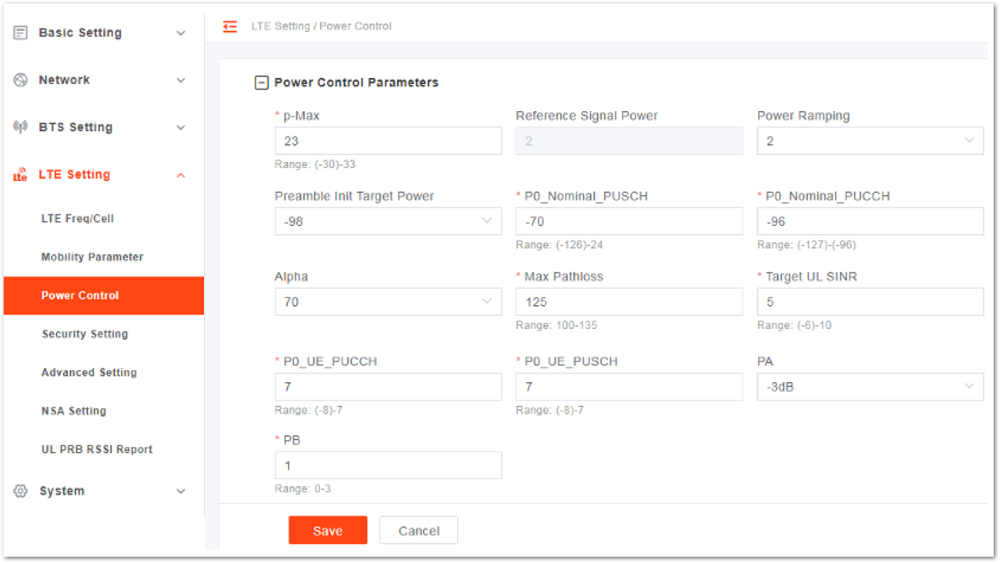 Figure 1: Power Control Parameter
Table 24: Power Control Parameter Description
| Parameter | Description |
|---|---|
| p-Max | The maximum transmitted power of the UE |
| Reference Signal Power | Transmit power of the reference signal |
| Power Ramping | Step size of the PRACH’s power ramping |
| Preamble Init Target Power | Initial power of PRACH |
| P0_Nominal_PUSCH | Initial transmit power of PUSCH |
| P0_Nominal_PUCCH | Initial transmit power of PUCCH |
| Alpha | Alpha parameter which controls the terminal power |
| Max Pathloss | The maximum of the path loss |
| Target UL SINR | The uplink target SNR corresponding to the max pass loss |
| P0_UE_PUCCH | The offset of different UE to the system nominal power P0_PUCCH |
| P0_UE_PUSCH | The offset of different UE to the system nominal power P0_PUSCH |
| PA | When the PDSCH power control PA adjustment switch and the downlink ICIC switch are disabled, the PDSCH uses the PA value for average power distribution. PA=10l gρA |
| PB | Represents the value of the power factor ratio of Energy Per Resource Element (EPRE) on PDSCH, and PB represents the index of ρB/ρA on the value. |
Security
DO NOT modify the value of the security parameters; keep the default values.
On the left navigation column, select LTE Setting > Security Setting to enter the security setting page.
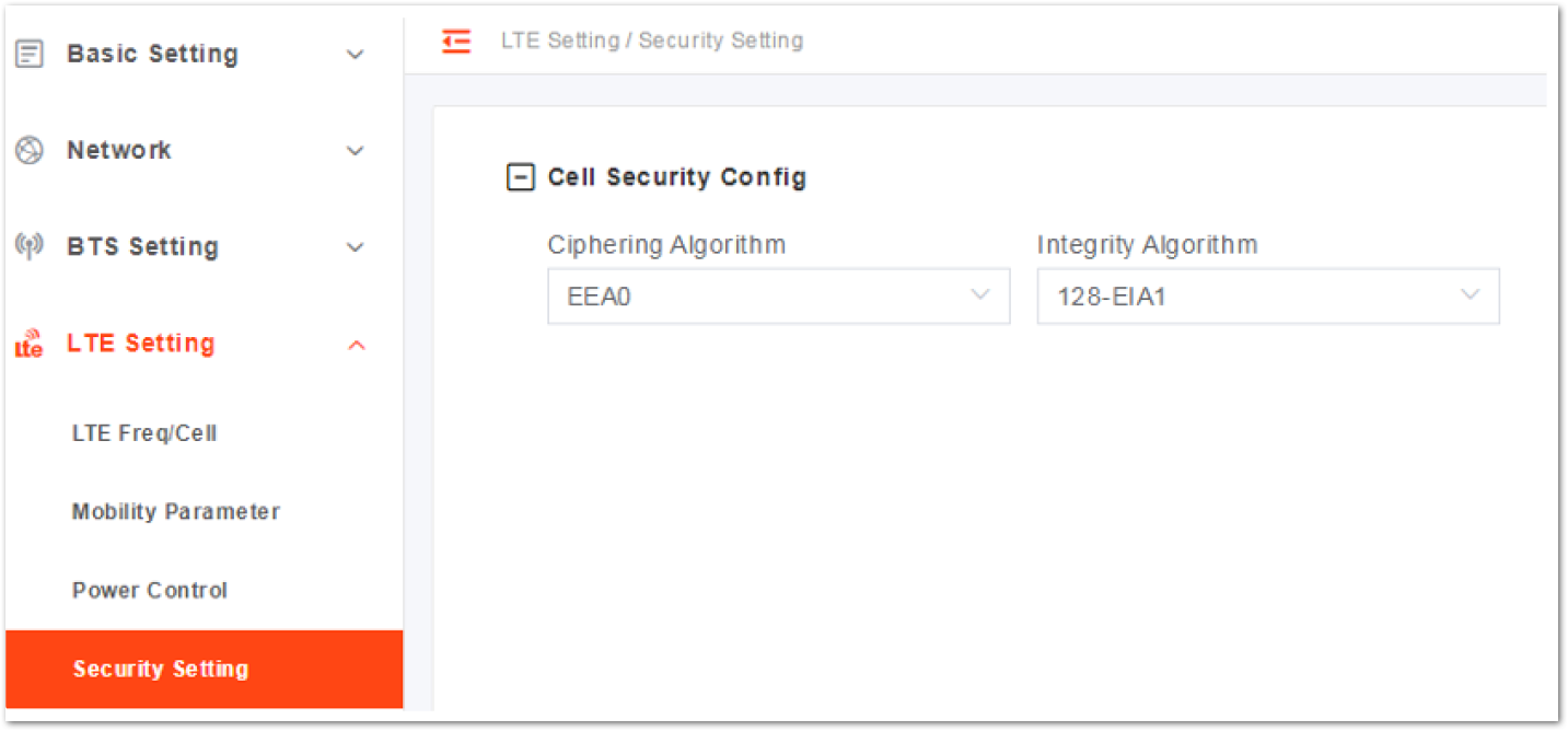 Figure 1: Configure Security
Table 25: Security Parameter Description
| Parameter | Description |
|---|---|
| Ciphering Algorithm | Encryption algorithm •EEA0(recommended) •128-EEA1 •128-EEA2 •Default: EEA0 |
| Integrity Algorithm | Integrity protection algorithm •128-EIA1 •128-EIA2 •Default: 128-EIA1 |
Advanced Parameter
On the left navigation column, select LTE Setting > Advanced Setting to enter the advanced parameter configuration page.
Random Access Parameters
To display the random access configuration parameter, click Random Access Parameters.
Table 26: Random Access Parameter Description
| Parameter | Description |
|---|---|
| Preamble Format | The preamble format when UE random accesses: •0: send PRACH on normal subframe, the farthest covered distance is 14 km. •4: send PRACH special subframe, the farthest covered distance is 1 km. |
| Prach-Configuration Index | PRACH configuration index, broadcasted to the UE via SIB2 •If Preamble Format is set to 0 and SubFrame Assignment is set to 1, the range is 0-7, 9-12, 15-19. •If Preamble Format is set to 0 and SubFrame Assignment is set to 2, the range is 0-4, 6, 9, 10, 12, 15, 16, 18. •If Preamble Format is set to 4, the range is 48-57. |
| Zero Correlation Zone Config | PRACH cycle shift, used to generate the preamble sequence: •If Preamble Format is set to 0, the range is 1-13. •If Preamble Format is set to 4, the range is 2-6. |
| PRACH Freq Offset | Set the frequency offset range, the value range is determined by the bandwidth of the quick Settings page: •If the bandwidth is 10 MHz, the range is 4-40. •If the bandwidth is 20 MHz, the range is 5-89. |
| Root Sequence Index | The index of root sequence. Range: 0-837 |
RRC Status Parameters
To display the RRC status configuration meters, click RRC Status Parameters.
Table 27: RRC Status Parameters
| Parameter | Description |
|---|---|
| UE Inactivity Timer | Expire time of the UE inactive status timer(s) |
| Max Expiry Count | Maximum number of the UE inactive status timer’s expiries |
UE Inactive Status Duration = RRC Inactive Timer * Max Expiry Count
Scheduling Algorithm
Scheduling is an important insurance for the good operation of the wireless data service. Scheduling algorithms have a general impact on key performance indicators like the cell throughput, cell edge user throughput, VoIP capacity, and QoS of data service.
RR Algorithm- RF Algorithm allocates the resources and opportunities to all terminals equally. QoS does not be considered, and memory not used.
- In PFS Algorithm, the user channel quality and fairness are considered comprehensively between cell throughput and user fairness.
- Different QoS is provided for different data bearer categories. Each data bearer category is associated with a QoS Class Identifier (QCI).
To display the random access configuration parameter, click Random Access Parameters.
Table 28: Scheduling Algorithms Parameter Description
| Parameter | Description |
|---|---|
| UL Schd Type | MAC uplink scheduling algorithm, support QoS, PFS and RR. Default: RR |
| DL Schd Type | MAC downlink scheduling algorithm, support PFS and RR. Default: RR |
Sync Adjust Setting
- Click Sync Adjust Setting to display the synchronization adjust configuration parameter.
- Input the value of frameShift.
- To complete the synchronization adjust setting, click Save.
Link Activation State Detector
To display the link activation state detector configuration parameters, click Link Activation State Detector.
Table 29: Scheduling Algorithms Parameter Description
| Parameter | Description |
|---|---|
| Link Keep Alive | Whether or not to enable the link keep alive. |
| Link Keep Alive Timer | When Link Keep Alive is set to Enable, the timer needs to be set. |
Working Mode
- Click Working Mode to display the working mode configuration parameter.
- Select the working mode: 32UE, 64UE, or 96UE.
- To complete the working mode setting, click Save.
UL 64QAM Setting
- Click UL 64QAM Setting to display the UL 64QAM setting parameter.
- Choose whether or not to enable 64QAM function.
- To complete the UL 64QAM setting, click Save.
DL 256QAM Setting
- Click DL 256QAM Setting to display the DL 256QAM setting parameter.
- Choose whether or not to enable the DL 256QAM function.
- To complete the DL 256QAM setting, click Save.
SSH Setting
- Click SSH Setting to display the SSH configuration parameter.
- Choose whether or not to enable the SSH function to allow SSH login.
- To complete the SSH setting, click Save.
Performance Optimization
To display the performance optimization parameters, click Performance Optimization.
Table 30: Performance Optimization Parameter Description
| Parameter | Description |
|---|---|
| Target BLER | Select target Block Error Rate (BLER): •3% (1:33) •5% (2:40) •10%(3:30) |
| UL SINR | Uplink Signal to Interference plus Noise Ratio (SINR) Range from -6 to 10. |
| Ping Packet Delay Optimization | Enable or disable the ping packet delay optimization function. |
| Dynamic Scheduling UE | Select whether or not to enable dynamic scheduling UE function. |
| Dynamic UL Target SINR | Select whether or not to enable the function. |
Signaling Trace
The Signaling Trace function is typically used for troubleshooting UE attachment and handover issues. It captures RRC and SCTP packets in real-time and sends them to a remote computer running Wireshark or a local OMC for analysis.
RRC is a protocol that regulates UE and eNB over-the-air communication. It is especially important during mobility scenarios when a mobile user is handed off from one eNB to another.
On the other hand, SCTP is a transport protocol layer for the S1-MME signaling bear. It is responsible for various tasks, such as:
- Evolved Packet System (EPS) bearer setup, modification, and release
- Handover procedures
- Non-Access Stratum (NAS) signaling transport
- Paging procedures
To display the signaling trace parameters, click Signaling Trace Setting. Then click Save to
Table 30: Performance Optimization Parameter Description
| Parameter | Description |
|---|---|
| RRC Signaling Trace Switch | Enable or disable the RRC signaling trace function. |
| RRC Signaling Trace OMC Format | Enable or disable sending the RRC signaling trace data to the local OMC. If the signaling trace is exported to the OMC, the parameter needs to be configured. |
| RRC Signaling Trace Dest IP | The IP address of the computer where RRC signaling trace data will be sent. The IP address must be communicated with the eNB. Default is 127.0.0.1, which should be changed. |
| RRC Signaling Trace Dest Port | The port number of the computer where RRC signaling trace data will be sent. Range is 1 to 65535. Default is 4337. NOTE: For MAC computer, if there is an existing MAC packet (directory), make sure to use a different port number for the RRC packet. |
| RRC Signaling Trace Duration | •The duration of the RRC signaling trace •Range is 0 to 30 minutes. •A value of zero (0) means continuous |
| SCTP Signaling Trace Enable Switch | Enable or disable the computer where SCTP signaling trace function. |
| SCTP Signaling Trace OMC Format | Enable or disable sending the SCTP signaling trace data to the local OMC. If the signaling trace is exported to the OMC, the parameter needs to be configured. |
| SCTP Signaling Trace Dest IP | The IP address of the computer where the SCTP signaling trace data will be sent. The IP address must be communicated with the eNB. Default is 127.0.0.1, which should be changed. |
| SCTP Signaling Trace Dest Port | The port number of the computer where the SCTP signaling trace data will be sent. |
| Range is 1 to 65535. Default is 36412. | |
| SCTP Signaling Trace Duration | •The duration of the SCTP signaling trace. •Range is 0 to 30 minutes. A value of zero (0) means continuous. |
NSA Setting
Non-standalone (NSA) is the 4G and 5G interoperating setting. When LGW function is set to OFF, the menu displays.
- Select LTE Setting > NSA Setting to enter the NSA configuration page.
 Figure 1: NSA settings
 Figure 1: Configure NS
Table 31: LTE Neighbor Frequency Parameter Description
| Parameter | Description |
|---|---|
| Index | The index is generated automatically. |
| PLMN | The numerical identifier for the operator's Public Land Mobile Network (PLMN) for this cell. Must be a 5 or 6-digit number. |
| NR CELL ID | The CELL ID of NR eNB. |
| DLEARFCN | The frequency point of the eNB’s downlink frequency. DL EARFCN stands for Evolved Universal Mobile Telecommunications System (UMTS) Terrestrial Radio Access (E-UTRA) Absolute Radio Frequency Channel Number. |
| ULEARFCN | The frequency point of the eNB’s uplink frequency. UL EARFCN stands for Evolved Universal Mobile Telecommunications System (UMTS) Terrestrial Radio Access (E-UTRA) Absolute Radio Frequency Channel Number. |
| PCI | Physical Cell Identifier (PCI) of the NR cell. |
| QOFFSET | •Frequency offset this NR cell. •Indicates the difference in signal level between the serving and this NR eNB, as determined by the received signal level at the UE. •If the received signal level is better from a neighboring eNB by at least this amount of difference in dB, the UE will reselect this cell. |
| Range is +24 to -24. A typical value is 0 dB. | |
| CIO | Cell Individual Offset (CIO) is this NR eNB’s cell offset, which is one of the variables used to determine which eNB will best serve a given UE. Range is +24 to -24. A typical value is 0 dB. |
| TAC | Tracking Area Code (TAC) of this neighbor cell. |
| GNB IP | The IP address of gNB. |
UL PRB RSSI Report
Select LTE Setting > UL PRB RSSI Report to enter the UL PRB Received Signal Strength Indication (RSSI) report configuration page.
 Figure 1: UL PRB RSSI Report Settings
The eNB provides three types of mode.
- No-load mode
- Regular mode
- Full band mode
If you choose one type of mode, the page will display the graph of UL PRB RSSI.
System Setting
Log
In the navigation column on the left, select System > Log to enter the log setting page.
 Figure 1: System log
- Click Get Log Files to save the log files to the local computer.
- Click Get Crash Logs to save the crash log files to the local computer.
- Click Get Core File to save the core files to the local computer.
Upgrade
When the current version does not meet the actual need, the software version needs to be updated to the latest version. The system supports firmware version upgrade and rollback.
Firmware upgrade may lead to the damage of the eNB file. Contact the support engineer before upgrading. If necessary, the vendor will provide the technical support.
In the navigation column on the left, select System > Upgrade.
 Figure 1: Software Upgrade
Upgrade Firmware
- Get new version of firmware file and save it to your local computer.
- Select whether or not to preserve the current settings.
- Click Select File to select the firmware file.
The file type is .IMG.
- Check whether the software version is correct again and then click Upgrade.
- In the pop-up window, click PROCEED. Wait for about three mins, the base station will reboot completely.
- In the Basic Setting > Basic Info page, the upgraded version will be displayed in Software Version.
Version Rollback
Only one rollback operation is allowed for each upgrade. By permission of the base station, the software can roll back to the version before upgrading.
After the rollback, a new rollback will not be permitted until an upgrade has taken place. If the previous version is -, then there is no software version for rollback.
- Click Rollback.
- In the pop-up window, click OK. Wait for about three mins, the base station will reboot completely.
- In the BTS Info > Basic Info page, the version after rollback will be displayed in Software Version.
Backup
In the navigation column on the left, select System > Backup to enter the backup page.
 Figure 1: System Backup
- Click Get Backup Files.
- In the pop-up download dialog box, select the file path to save the current configuration file to the local computer.
- Click Select File to import the configuration file.
After the restore operation, the base station will reboot immediately. Be careful when using the Restore Default Configuration feature.
To reboot immediately, click Restore Default Configuration.
NTP
The NTP page includes the time zone and the NTP configuration, which are configured based on the needs. If the NTP is used as an external clock source by the base station, up to three NTP servers are supported: one for the master NTP service and two for backup.
- In the navigation column on the left, select System > NTP to enter the NTP setting page.
 Figure 1: NTP Server Setting
- Select the time zone where the eNB located.
- Choose whether or not to enable or disable the NTP function.
- Input the parameters, then click Save to complete the NTP server configuration.
| Parameter | Description |
|---|---|
| Port Port number of the primary NTP server. Must be consistent with the other end. | |
| Server1 | Domain name or IP address of the primary NTP server. Must be consistent with the other end. |
| Server2 | Domain name or IP address of a secondary NTP server. Must be consistent with the other end. |
| Server3 | Domain name or IP address of a secondary NTP server. Must be consistent with the other end. |
Network Diagnostics
- In the navigation column on the left, select Network > Diagnostics to enter the diagnostics page.
The eNB supports three types of network diagnosis methods:
- Ping
Ping command is used to check whether the network connection from the eNB to the destination IP address is normal.
Table 32: Ping Parameter Description of Diagnostics
| Parameter | Description |
|---|---|
| Target IP/Domain | The IP address or domain name of the destination |
| Packet Size | The size of the packet |
| Timeout | Set the timeout period |
| Packet Num | The number of packets sent |
- Traceroute
Traceroute command is used to detect the routing information between the eNB and the destination IP address.
Table 33: Traceroute Parameter Description of Diagnostics
| Parameter | Description |
|---|---|
| Target IP/Domain | The IP address or domain name of the destination. |
| Timeout | Set the timeout period. |
| Maximum Hops | The maximum number of hops. |
- Iperf3
Iperf3 command is used to check the network performance.
Table 33: Iperf3Parameter Description of Diagnostics
| Parameter | Description |
|---|---|
| Iperf Mode | Iperf Mode is set to client or server. |
| Iperf IP Address | IP Address of Iperf used. |
| Iperf Port | Port of Iperf used. |
- Select what Methods of Diagnostics you want to set.
- Enter the parameters, then click Implement.
The result of the operation is displayed in the lower part of the screen.
 Figure 1: Network Diagnostics
Web Access Setting
Web Access Setting describes how to enable SSH and change the login port of the LMT. The default port is 443. If there is any conflict in the network, the port can be changed. After changing the port, the login URL must add the port number: https://<IP address>:<port number>.
- In the navigation column on the left, select System > Web Access Setting to enter the web access setting page.
 Figure 1: Web Access Setting
- Input a new port, and click Save to complete the web access change.
Certificate
eNB supports upgrading and managing IPsec CA, IPsec equipment, IPsec private, and SAS CPI certificates.
An SAS CPI certificate permits access to Spectrum Access System (SAS). If the operator requires use of certificates, they will provide the certificates.
The file types of the certificate are .pem or .der generally.
- Select System > Certificate to enter the certificate management page.
 Figure 1: Certificate
For IPsec related certificates, you can also check IPsec Configuration section.
- Click Select File, then select a certificate from your local computer to upload the certificate file to the eNB.
License Management
The License Management menu can be used to import license files for optional features, such as regulatory certificates of authorization to operate. When imported, the files are stored in the eNB memory and displayed in the License List area of this window.
The bottom half of the window pertains licenses for using one or more 1588v2 servers for transmission timing synchronization.
- In the left navigation column, select System > License to enter the License Management page.
 Figure 1: License Management
- Select the License file from the local computer.
- Click Select File to upload the license file to the eNB. After the License file is uploaded, it will display in the license list.
Reboot
The reboot operation will interrupt the current service of the base station, so be careful when performing this operation.
- On the left navigation, select System > Reboot to enter the reboot window.
- Click Reboot to reboot the eNB immediately.
Wait for 3-5 minutes, and the eNB will restart completely. After the eNB reboots, it is recommended to modify the time setting.
