RAK12023 WisBlock Soil Moisture Sensor Connector Module Quick Start Guide
Prerequisite
Package Inclusions
Before going through each and every step on using the RAK12023 WisBlock module, make sure to prepare the necessary items listed below:
Hardware
- RAK12023 & RAK12035 WisBlock Soil Moisture Sensor Module
- Your choice of WisBlock Base with IO slot
- Your choice of WisBlock Core
- USB Cable
- RAK19008 WisBlock IO Extension Cable (optional)
- Li-Ion/LiPo battery (optional)
- Solar charger (optional)
Software
- Download and install the ArduinoIDE.
- To add the RAKwireless Core boards on your Arduino board, install the RAKwireless Arduino BSP. Follow the steps in the GitHub repo.
Product Configuration
Hardware Setup
RAK12023 is a soil moisture connector module. It has one (1) standard WisBlock IO connector, which you can connect with the WisBlock Base. It also has three (3) connectors dedicated to the RAK12035. RAK12035 is a separate soil moisture sensor probe that can be connected to the RAK12023 module. Only one RAK12035 soil moisture sensor can be connected to the RAK12023 simultaneously.
For more information about RAK12023, refer to the Datasheet.
The RAK12023 module gives information about:
- Soil Moisture
- Soil Temperature
RAK12023 module can be connected to the IO slot of WisBlock Base to communicate with the WisBlock Core, as shown in Figure 1. Also, always secure the connection of the WisBlock module by using compatible screws.
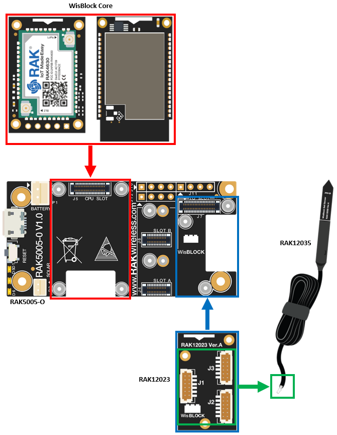 Figure 1: RAK12023 connection to WisBlock Base
RAK12035 Soil Moisture Sensor Probe
A separate sensor PCB module RAK12035 is required. The RAK12035 is a sensor probe that you need to bury into the soil to measure the moisture of the soil.
For more information about RAK12035, refer to the RAK12035 Soil Moisture Sensor Overview.
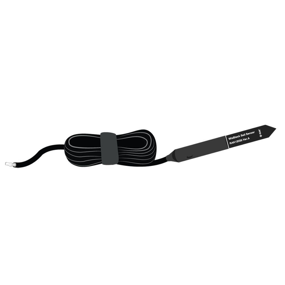 Figure 1: RAK12035 Soil Moisture Sensor
Assembling and Disassembling of WisBlock Modules
Assembling
The RAK12023 module can be mounted on the IO slot of the WisBlock Base board, as shown in Figure 3. Also, always secure the connection of the WisBlock module by using compatible screws.
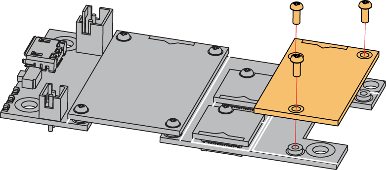 Figure 1: RAK12023 mounting connection to WisBlock Base module
Disassembling
The procedure in disassembling any type of WisBlock modules is the same.
- First, remove the screws.
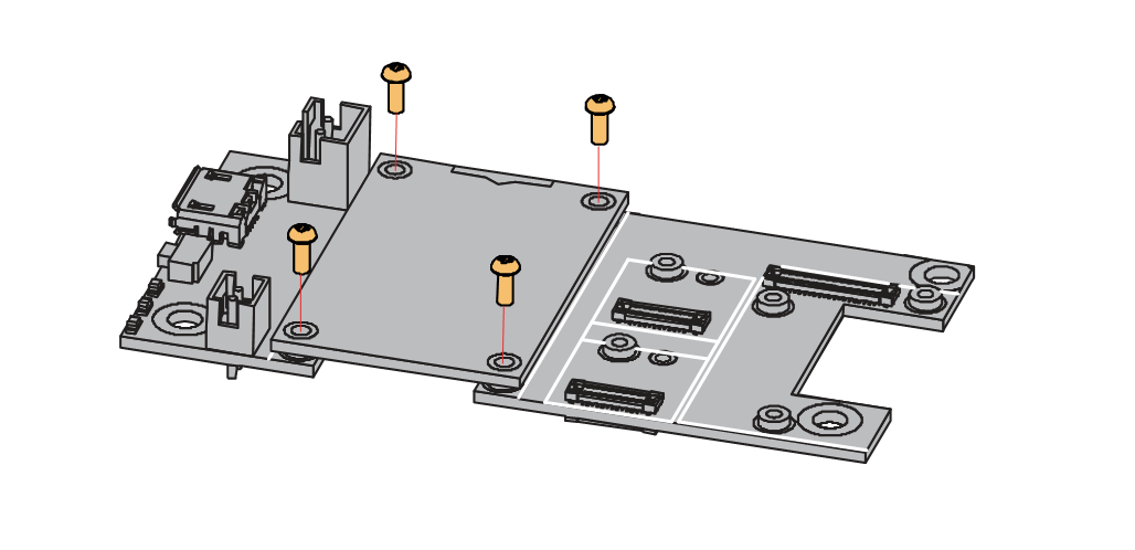 Figure 1: Removing screws from the WisBlock module
- Once the screws are removed, check the silkscreen of the module to find the correct location where force can be applied.
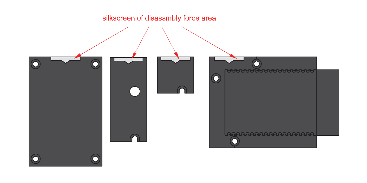 Figure 1: Detaching silkscreen on the WisBlock module
- Apply force to the module at the position of the connector, as shown in Figure 6, to detach the module from the baseboard.
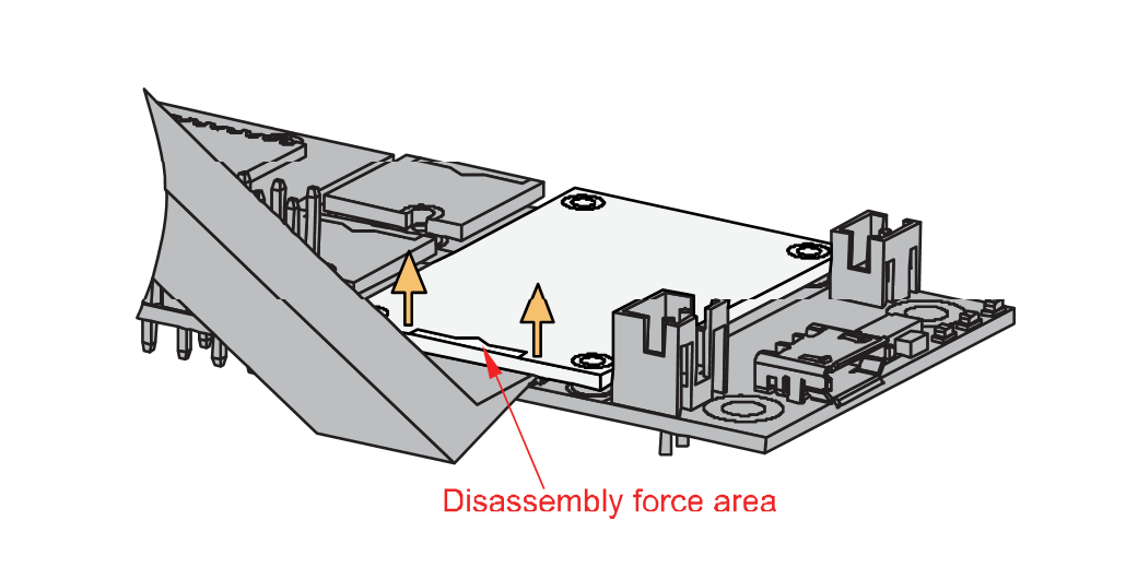 Figure 1: Applying even forces on the proper location of a WisBlock module
If you will connect other modules to the remaining WisBlock Base slots, check on the WisBlock Pin Mapper tool for possible conflicts.
After all this setup, you can now connect the battery (optional) and USB cable to start programming your WisBlock Core.
- Batteries can cause harm if not handled properly.
- Only 3.7-4.2 V Rechargeable LiPo batteries are supported. It is highly recommended not to use other types of batteries with the system unless you know what you are doing.
- If a non-rechargeable battery is used, it has to be unplugged first before connecting the USB cable to the USB port of the board to configure the device. Not doing so might damage the battery or cause a fire.
- Only 5 V solar panels are supported. Do not use 12 V solar panels. It will destroy the charging unit and eventually other electronic parts.
- Make sure the battery wires match the polarity on the WisBlock Base board. Not all batteries have the same wiring.
Software Configuration and Example
Initial Test of the RAK12023 WisBlock Module
Before you use the Soil Moisture sensor, you need to calibrate it. The following steps below will show you the example sketch for calibration. The calibration values will be saved on the RAK12035 sensor itself so that you can read them back later from the sensor. In the first step, the sensor is calibrated by reading the sensor values while the sensor is in the air. In the next step submerge the sensor in water (only to the white line on the sensor). After the calibration is finished, the example sketch will save the calibration values directly in the sensor. The value measured in the air corresponds to 0% RH, the value measured in water corresponds to 100% RH.
REMARK
The calibration method in air and water is not very precise. To get more precise calibration values, the calibration should be performed in dry soil and water-saturated soil. Some information about such a calibration procedure is shown in Capacitive Soil Moisture Sensor Calibration with Arduino. Another source for such a calibration in the soil can be found in Calibrating Soil Moisture Sensors.
-
Install the RAKwireless Arduino BSP for WisBlock by using the
package_rakwireless_index.jsonboard installation package. The WisBlock Core should now be available on the Arduino IDE. -
You need to select first the WisBlock Core you have.
RAK4631 Board
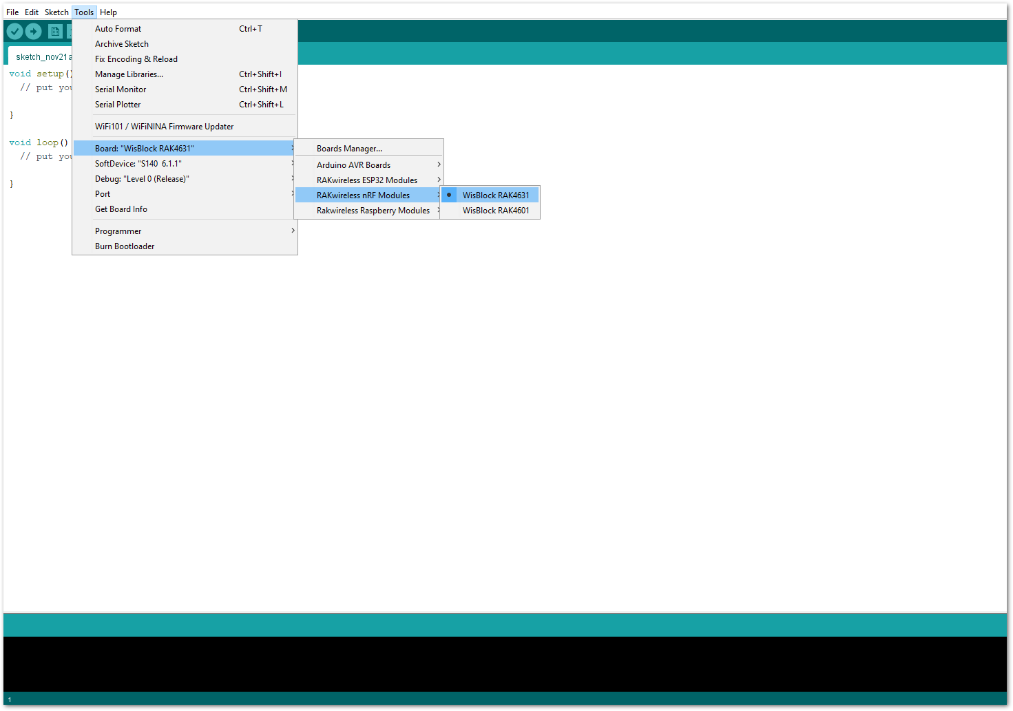 Figure 1: Selecting RAK4631 as WisBlock Core
RAK11200 Board
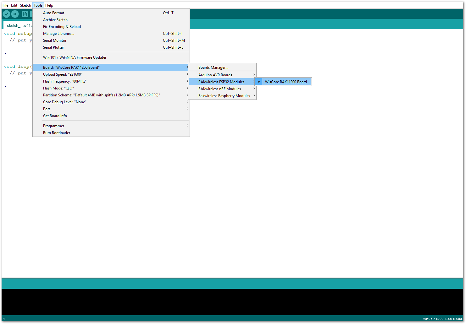 Figure 1: Selecting RAK11200 as WisBlock Core
RAK11310 Board
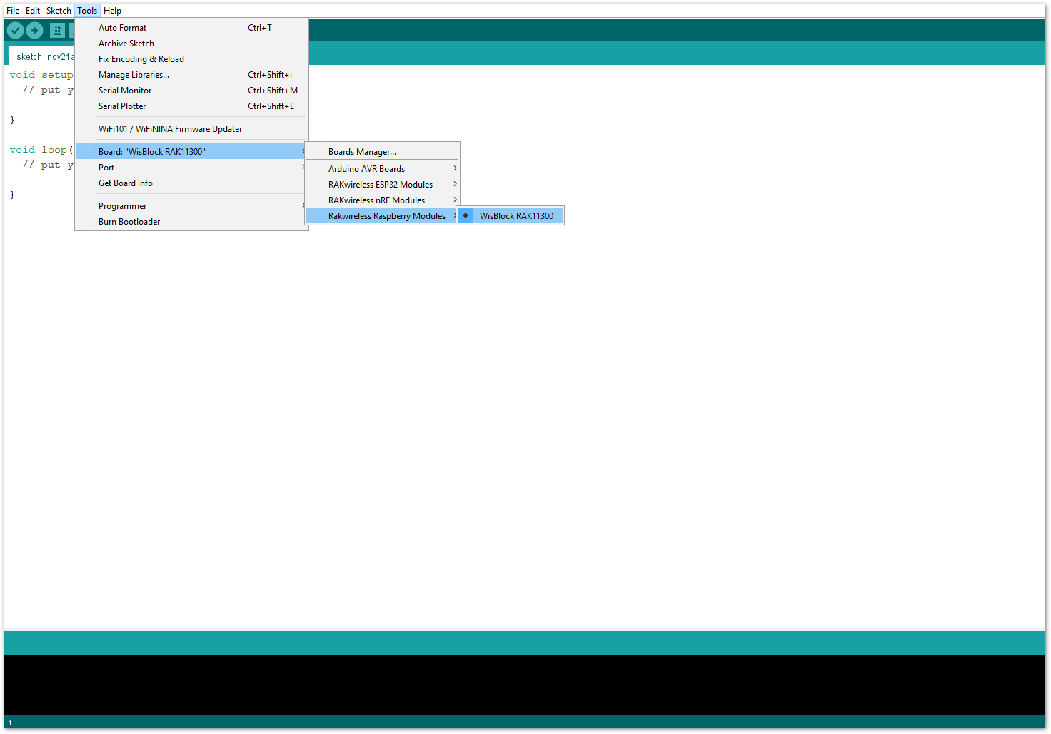 Figure 1: Selecting RAK11310 as WisBlock Core
- Next, copy the following sample code into your Arduino IDE:
Click to view the code
/**
 * @file RAK12035_Calibration.ino
 * @author Bernd Giesecke (bernd.giesecke@rakwireless.com)
 * @brief Example for sensor calibration
 * @version 0.1
 * @date 2021-11-20
 *
 * @copyright Copyright (c) 2021
 *
*/
#include <Arduino.h>
#include <Wire.h>
#include "RAK12035_SoilMoisture.h" // Click here to get the library: http://librarymanager/All#RAK12035_SoilMoisture

/** Sensor */
RAK12035 sensor;

/** Set these two values after the sensor calibration was done */
uint16_t zero_val = 845;
uint16_t hundred_val = 635;

void setup()
{
	// Initialize the built in LED
	pinMode(LED_GREEN, OUTPUT);
	digitalWrite(LED_GREEN, LOW);

	// Initialize the connection status LED
	pinMode(LED_BLUE, OUTPUT);
	digitalWrite(LED_BLUE, HIGH);

	// Initialize Serial for debug output
	Serial.begin(115200);

	time_t serial_timeout = millis();
	// On nRF52840 the USB serial is not available immediately
	while (!Serial)
	{
		if ((millis() - serial_timeout) < 5000)
		{
			delay(100);
			digitalWrite(LED_GREEN, !digitalRead(LED_GREEN));
		}
		else
		{
			break;
		}
	}
	digitalWrite(LED_GREEN, LOW);

	Wire.begin();

	// Initialize sensor
	sensor.begin();

	// Get sensor firmware version
	uint8_t data = 0;
	sensor.get_sensor_version(&data);
	Serial.print("Sensor Firmware version: ");
	Serial.println(data, HEX);
	Serial.println();

	// Because each sensor has differences, it is required to calibrate the sensors
	// First get the values of a sensor in dry air
	Serial.println("Sensor Calibration");
	Serial.println("Keep the sensor in a dry environment (air) and press ENTER to start the first calibration");
	Serial.println("The calibration steps takes some time as an average is calculated out of 100 sensor readings.");

	Serial.println("\nPress ENTER when ready.");

	while (!Serial.available())
	{
		delay(200);
	}
	Serial.println("Start dry calibration.");
	while (Serial.available())
	{
		Serial.read();
	}

	uint16_t new_reading = 0;
	uint16_t new_value = 0;
	digitalWrite(LED_GREEN, LOW);
	digitalWrite(LED_BLUE, HIGH);

	sensor.get_sensor_capacitance(&new_value);
	for (int readings = 0; readings < 100; readings++)
	{
		sensor.get_sensor_capacitance(&new_reading);
		new_value += new_reading;
		new_value = new_value / 2;
		delay(250);
		digitalWrite(LED_GREEN, !digitalRead(LED_GREEN));
		digitalWrite(LED_BLUE, !digitalRead(LED_BLUE));
	}
	// Save the result
	zero_val = new_value;
	Serial.print("Calibration in dry air finished, average capacitance is ");
	Serial.println(new_value);
	Serial.println("=======================================");

	Serial.println("Now submerge the sensor into water up to the white line on the sensor and press ENTER to start the second calibration");
	Serial.println("The calibration steps takes some time as an average is calculated out of 100 sensor readings.");

	Serial.println("\nPress ENTER when ready.");

	while (!Serial.available())
	{
		delay(200);
	}
	Serial.println("Start wet calibration.");
	while (Serial.available())
	{
		Serial.read();
	}

	new_value = 0;
	digitalWrite(LED_GREEN, LOW);
	digitalWrite(LED_BLUE, HIGH);

	sensor.get_sensor_capacitance(&new_value);
	for (int readings = 0; readings < 100; readings++)
	{
		sensor.get_sensor_capacitance(&new_reading);
		new_value += new_reading;
		new_value = new_value / 2;
		delay(250);
		digitalWrite(LED_GREEN, !digitalRead(LED_GREEN));
		digitalWrite(LED_BLUE, !digitalRead(LED_BLUE));
	}
	// Save the result
	hundred_val = new_value;
	Serial.print("Calibration in water finished, average capacitance is ");
	Serial.println(new_value);
	Serial.println("=======================================");
	digitalWrite(LED_GREEN, LOW);
	digitalWrite(LED_BLUE, LOW);

	/** Here we are saving the calibration values in the sensor itself */
	sensor.set_dry_cal(zero_val);
	sensor.set_wet_cal(hundred_val);
}

void loop()
{
	// Read capacitance
	uint16_t capacitance = 0;
	sensor.get_sensor_capacitance(&capacitance);
	Serial.print("Soil Moisture Capacitance: ");
	Serial.println(capacitance);

	// Read moisture in %
	// after calibration, we get the Capacitance in air and in water, like zero_val and B. zero_val means 0% and B means 100%.
	// So the humidity is humidity =  (Capacitance-A) / ((B-A)/100.0)
	uint8_t moisture = 0;
	sensor.get_sensor_moisture(&moisture);
	Serial.print("Soil Moisture humidity(%): ");
	Serial.println(moisture);

	// Read temperature
	uint16_t temperature = 0;
	sensor.get_sensor_temperature(&temperature);
	Serial.print("Soil Moisture Temperature: ");
	Serial.print(temperature / 10);
	Serial.println(" *C");
	Serial.println("===========================");
	delay(1000);
}
The above sample code is the RAK12035 Calibration code. If you experience any error in compiling the example sketch, check the updated code for your WisBlock Core Module that can be found on the RAK12035 WisBlock Example Code Repository and this sample code in Github will work on all WisBlock Core.
Other sample code in the WisBlock Github Repository:
- Once the example code is open, install the RAK12035_SoilMoisture library by clicking the yellow highlighted link, as shown in Figure 10 and Figure 11.
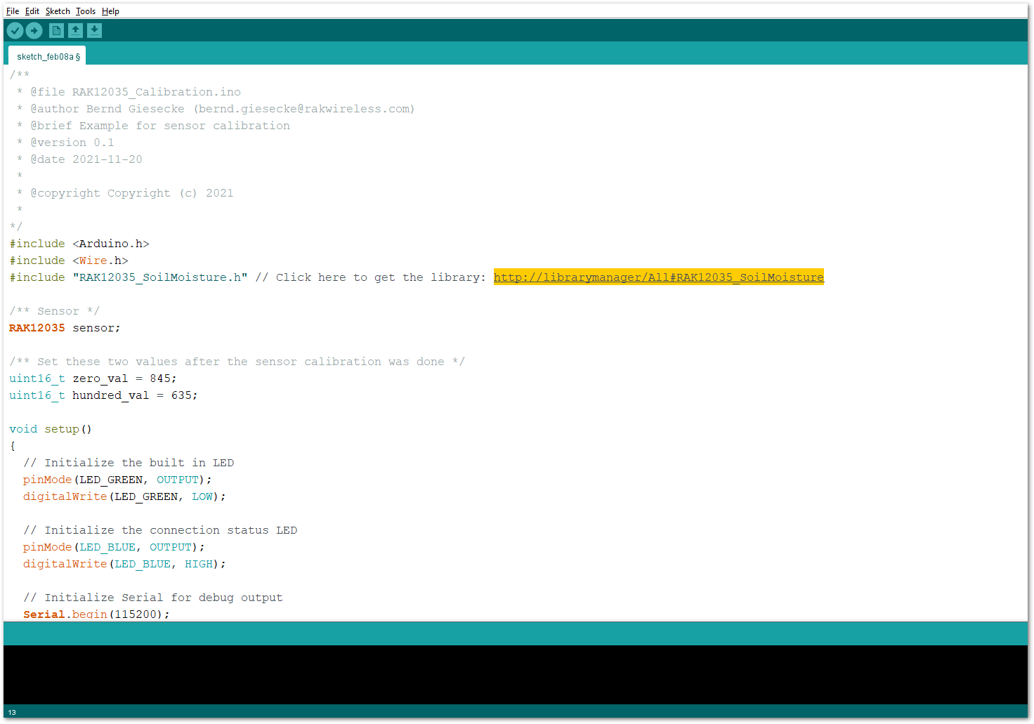 Figure 1: Accessing the library used for RAK12023 Module
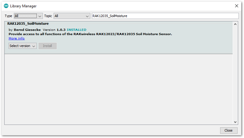 Figure 1: Installing the compatible library for RAK12023 Module
- After the successful installation of the library, you can now select the right serial port and upload the code, as shown in Figure 12 and Figure 13.
If you're using the RAK11200 as your WisBlock Core, the RAK11200 requires the Boot0 pin to be configured properly first before uploading. If not done properly, uploading the source code to RAK11200 will fail. Check the full details on the RAK11200 Quick Start Guide.
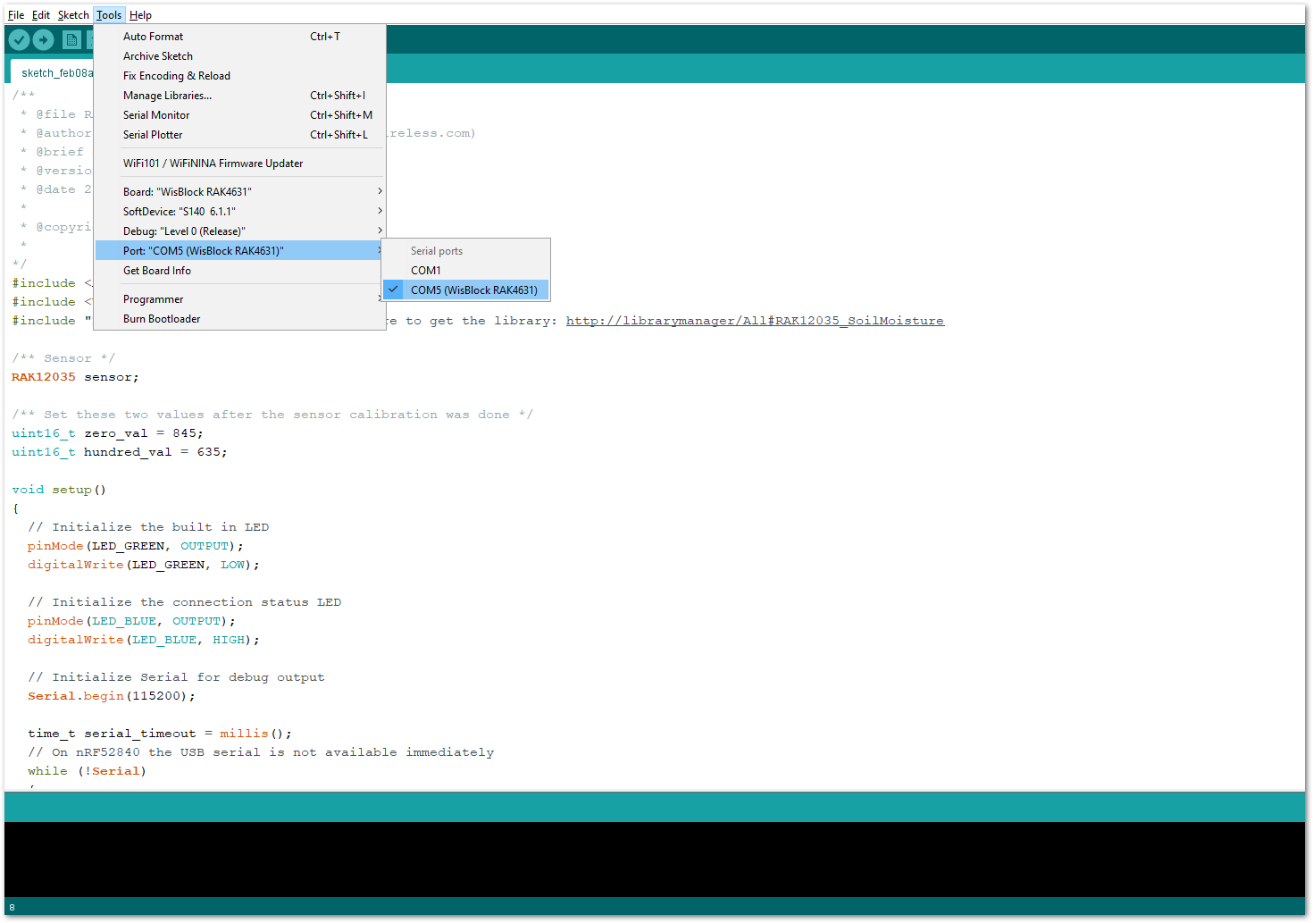 Figure 1: Selecting the correct Serial Port
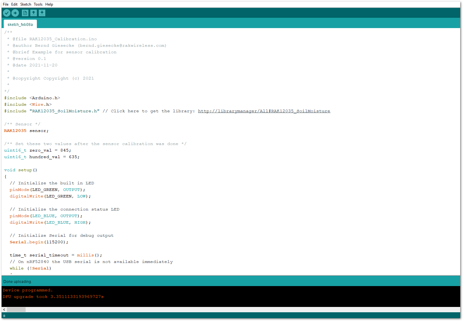 Figure 1: Uploading the RAK12023 example code
- When you successfully uploaded the example sketch, open the Serial Monitor of the Arduino IDE and select the settings of the Serial Monitor, as shown below in Figure 14. Set it into "Newline" and set the baud rate correctly.
 Figure 1: Setting up the Serial Monitor
- Finally, after setting up the Serial Monitor, you'll now be able to see the readings as shown below in Figure 15. Follow the steps carefully for you to be able to calibrate your sensor correctly.
Upon calibration and before submerging the sensor into the water, following the Recommended Depth of the RAK12035 Sensor probe is required.
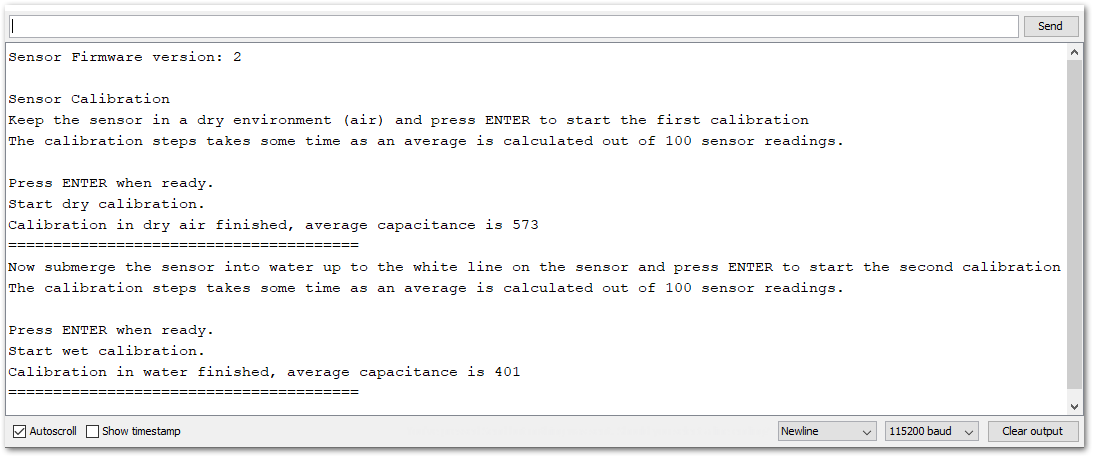 Figure 1: Calibrating the RAK12035 Sensor