RAK14000 WisBlock E-Ink Display Quick Start Guide
Prerequisite
What Do You Need?
Before going through each and every step on using RAK14000 WisBlock E-Ink Display, make sure to prepare the necessary items listed below:
Hardware
- RAK14000 WisBlock E-Ink Display
- WisBlock Base
- Your choice of WisBlock Core
- USB Cable
- Li-Ion/LiPo battery (optional)
- Solar charger (optional)
Software
Arduino
- Download and install Arduino IDE.
- To add the RAKwireless Core boards on your Arduino Boards Manager, install the RAKwireless Arduino BSP.
Product Configuration�
Hardware Setup
The RAK14000 module is part of the WisBlock Display category and connects to the baseboard through the IO slot. It has an E-Paper and a three-pushbutton interface that is connected via an FPC connector, as shown in Figure 1.
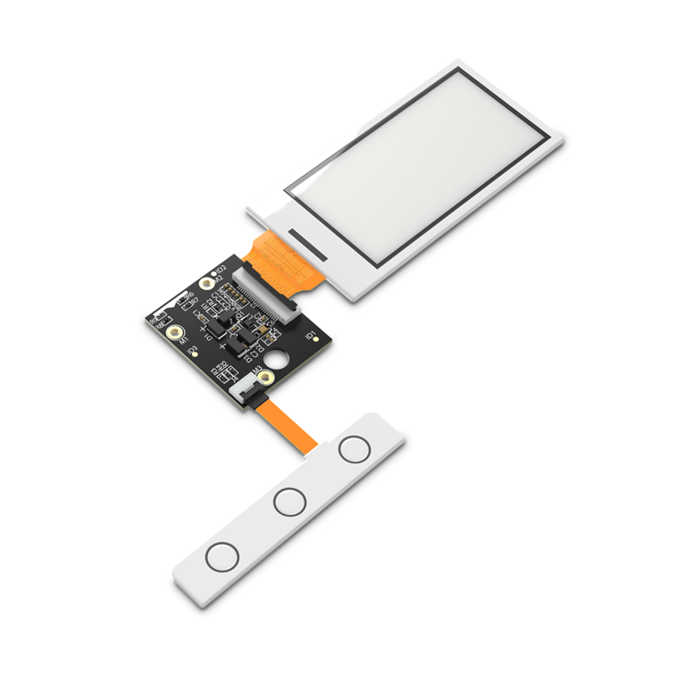 Figure 1: RAK14000 E-Paper and Three-Pushbutton Interface
Assembling and Disassembling of WisBlock Modules
Assembling
As shown in Figure 2, the location for the IO slot is properly marked by silkscreen. Follow carefully the procedure defined in RAK5005-O module assembly/disassembly instructions to attach a WisBlock module. Once attached, carefully fix the module with one or more pieces of M1.2 x 3 mm screws depending on the module.
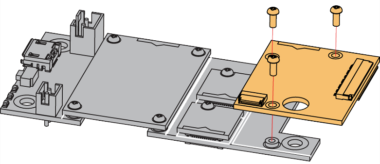 Figure 1: RAK14000 connection to WisBlock Base
Disassembling
The procedure to disassemble any type of WisBlock modules is the same.
- Remove the screws.
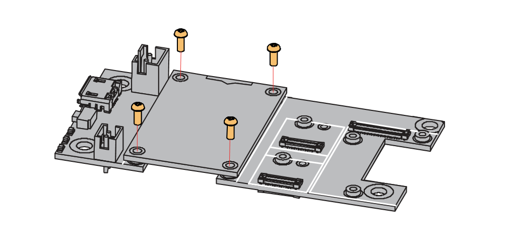 Figure 1: Removing screws from the WisBlock module
- Once the screws are removed, check the silkscreen of the module to find the correct location where force can be applied.
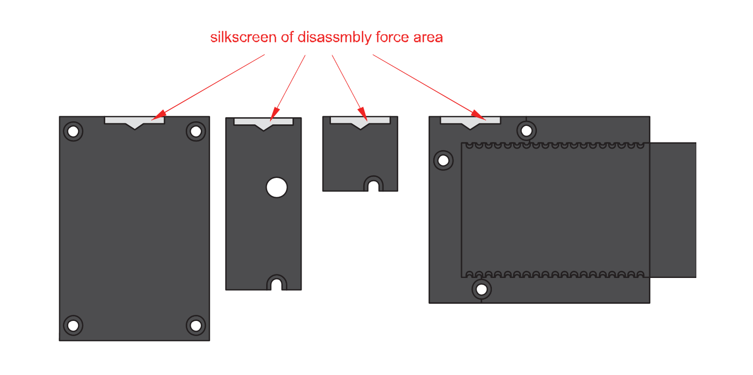 Figure 1: Detaching silkscreen on the WisBlock module
- Apply force to the module at the position of the connector, as shown in Figure 5, to detach the module from the baseboard.
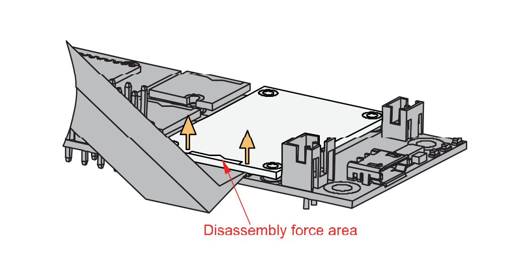 Figure 1: Applying even forces on the proper location of a WisBlock module
Connecting the E-Paper and the Three-Pushbutton Switch
Some illustrations are specific to the FPC connector of the Three-Pushbutton Switch, but it is also applicable to the E-Paper.
- The FPC connectors for the E-Paper and Pushbuttons are commonly set to close by default, as shown in Figure 6.
 Figure 1: RAK14000 FPC Connector Closed
- You need to open the lock of the FPC connector by carefully pulling it up. Then insert fully and carefully the FPC cable of the E-Paper and the Three-Pushbutton Switch with the copper trace facing down to the connector, as shown in Figure 7.
The E-Paper can be connected on either of the two FPC connectors. These are J2 and J3 in the RAK14000 board. This gives you flexibility on the orientation of the E-Paper display.
 Figure 1: RAK14000 FPC Connectors Open
- Once done, make sure to lock the FPC connection again by carefully pushing down the lock until the FPC cable tightens, as shown in Figure 8.
 Figure 1: RAK14000 FPC Correct Connection
If the copper trace is on top, as shown in Figure 9, that is a wrong connection, and the E-Paper and Three-Pushbutton Switch will not work.
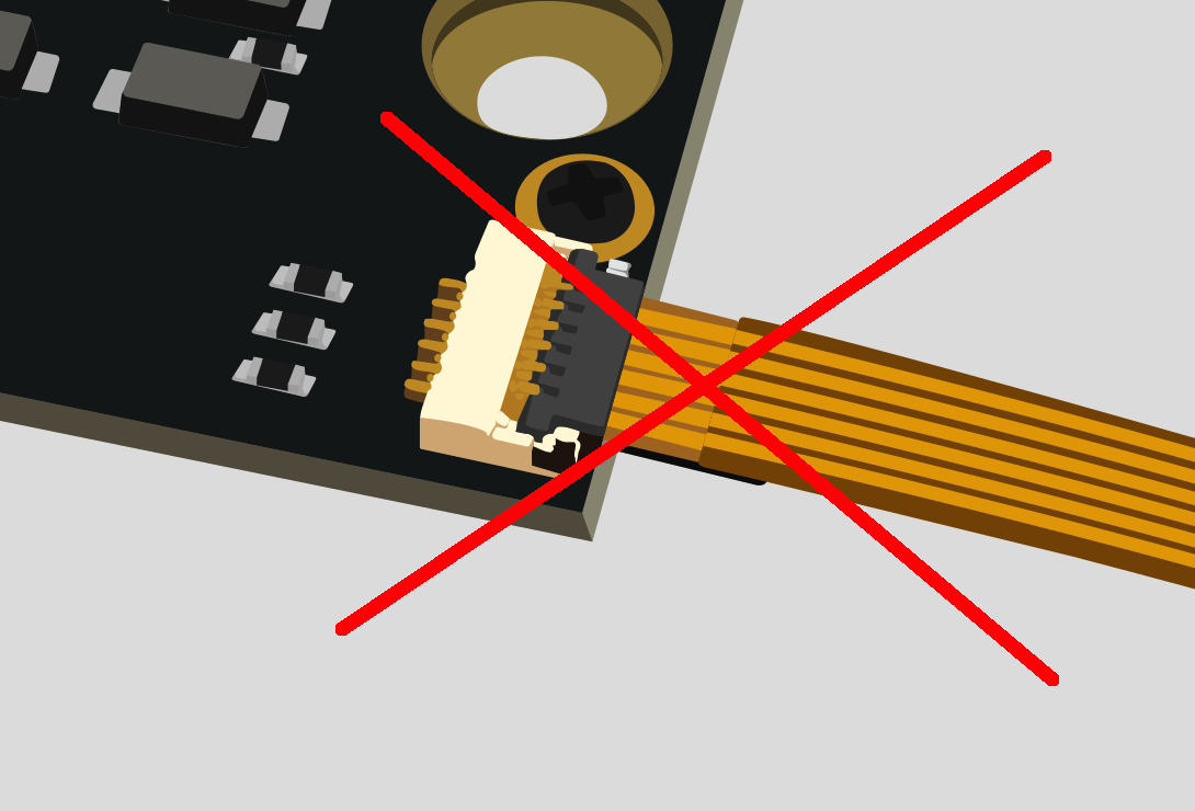 Figure 1: RAK14000 FPC Wrong Connection
If you will connect other modules to remaining WisBlock Base slots, check on the WisBlock Pin Mapper tool for possible conflicts. For instance, if you are planning to use it in conjunction with the EEPROM module, since the EPD uses all IO pins, you would have to forego the Three-Pushbutton Switch (uses IO 3, 5 and 6) and put the EEPROM module on slot D (has IO 5 & 6).
After all this setup, you can now connect the battery and USB cable to start programming your WisBlock Core.
Software Configuration and Example
In this example, you will be using E-Paper and the Three-Pushbutton Switch to demonstrate functionality.
These are the quick links that go directly to the software guide for the specific WisBlock Core module you use:
- RAK14000 in RAK4631 WisBlock Core Guide
- RAK14000 in RAK11200 WisBlock Core Guide
- RAK14000 in RAK11310 WisBlock Core Guide
RAK14000 in RAK4631 WisBlock Core Guide
Arduino Setup
If you already installed the RAKwireless Arduino BSP, the WisBlock Core and example code should now be available on the Arduino IDE.
- Select the RAK4631 WisBlock Core you have, as shown in Figure 10.
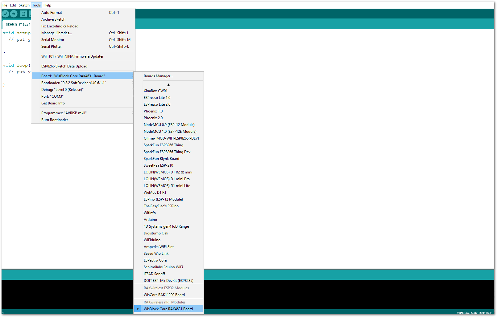 Figure 1: Selecting RAK4631 as WisBlock Core
- Install the Adafruit GFX Library.
- Open the Arduino IDE.
- On the Menu bar, click Sketch > Include Library > Manage Libraries.
- On the Library Manager text area, type adafruit gfx.
- To finish installation, click on the Install button highlighted in yellow, as shown in Figure 11.
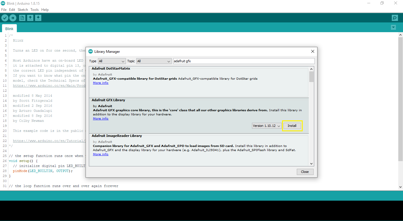 Figure 1: Adafruit GFX Library Install
- Install the Adafruit EPD Library.
- Open the Arduino IDE.
- On the Menu bar, click Sketch > Include Library > Manage Libraries.
- On the Library Manager text area, type adafruit epd.
- To finish installation, click on the Install button highlighted in yellow, as shown in Figure 12.
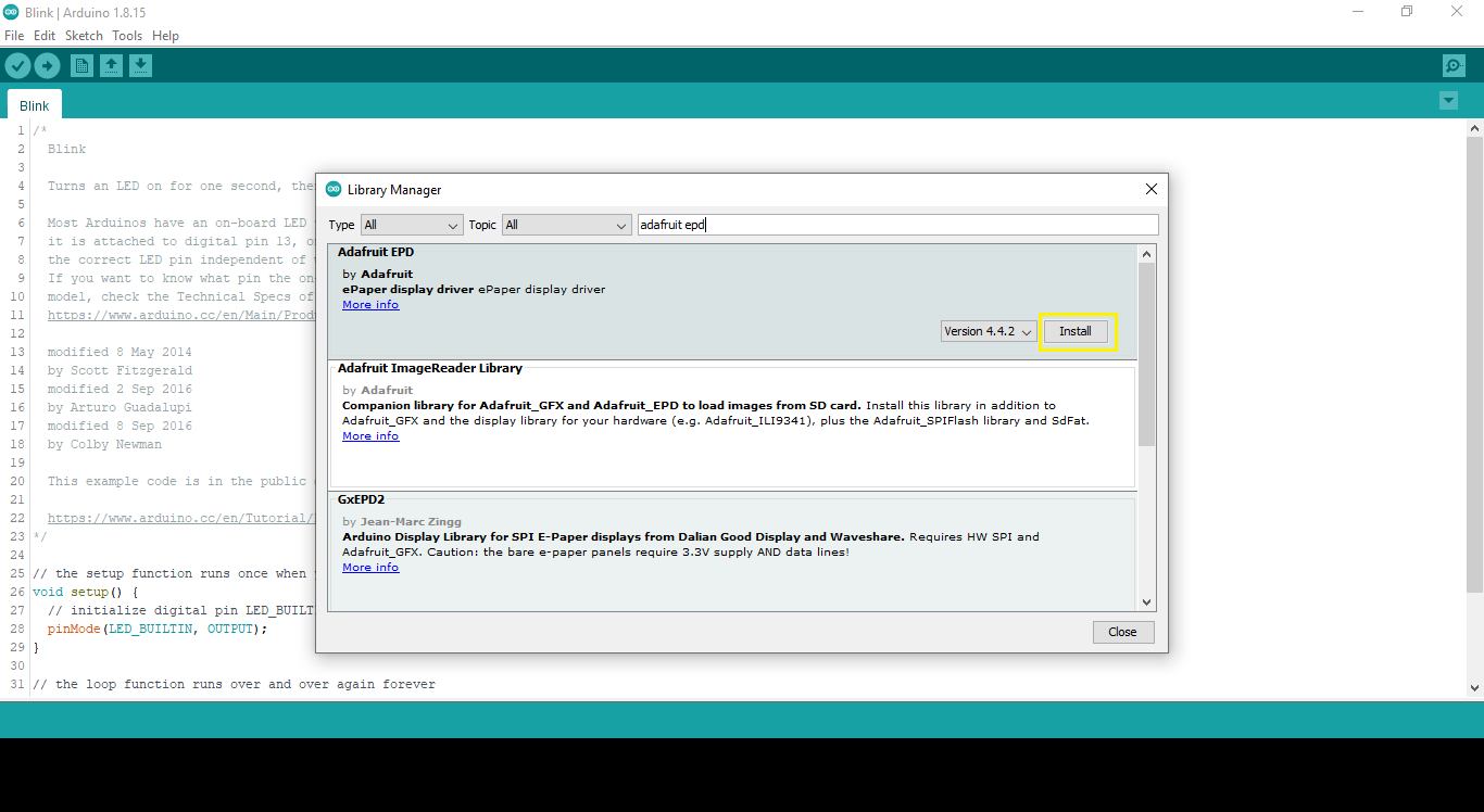 Figure 1: Adafruit EPD Library Install
- You can access the programming guide for the RAK14000 module by opening the example codes, as shown in Figure 13.
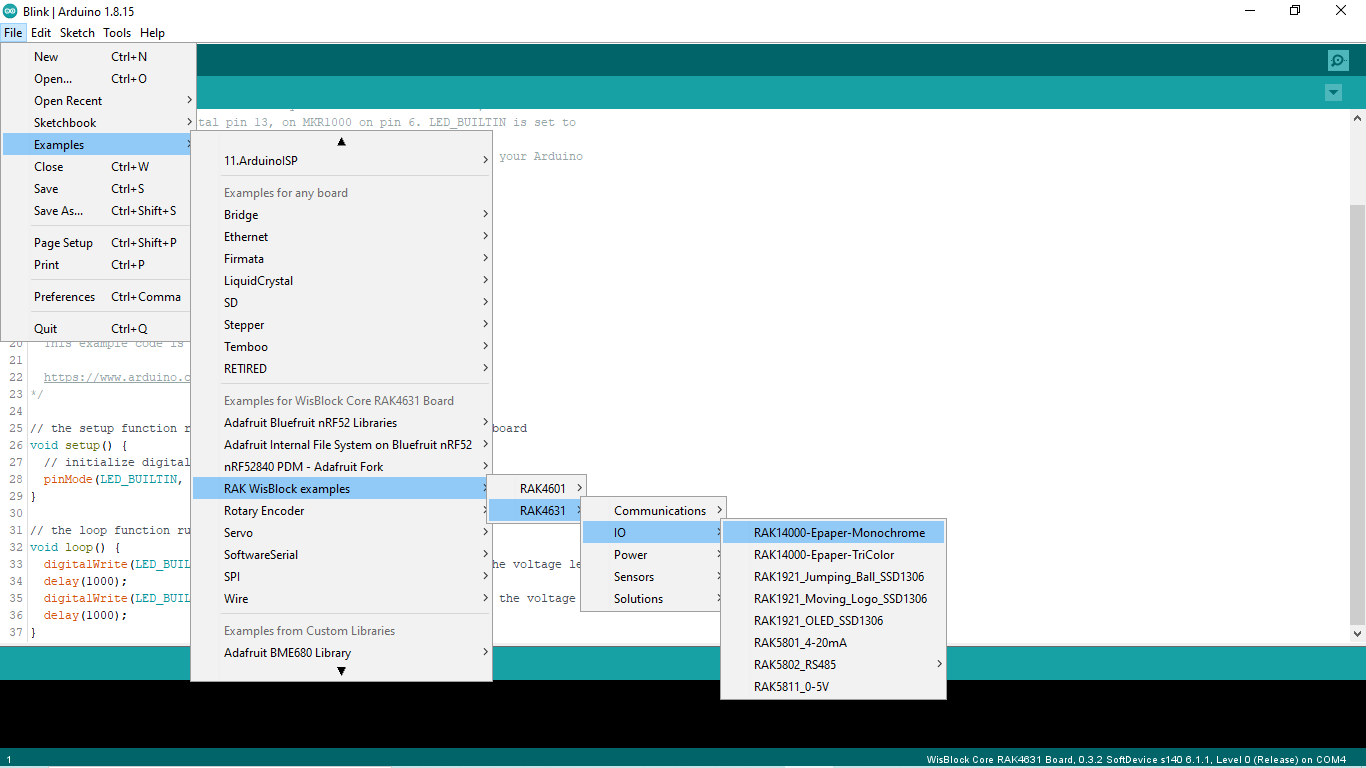 Figure 1: Opening RAK14000 example for RAK4631 WisBlock Core
You will need to change this section of the code if you are using an E-Paper with different resolution from another vendor.
typedef struct  DEPG {
   int  width;
   int  height;
   int  position1_x;
   int  position1_y;
   int  position2_x;
   int  position2_y;
   int  position3_x;
   int  position3_y;
   int  position4_x;
   int  position4_y;
} DEPG;

// DEPG  DEPG_HP = {250,122,40,20,40,30,40,50,90,40};  //use this for white-black-red version
DEPG  DEPG_HP = {212,104,30,15,30,25,30,45,80,30};  //  use this for white-black version

Adafruit_SSD1680 display(DEPG_HP.width, DEPG_HP.height, EPD_MOSI,
                         EPD_SCK, EPD_DC, EPD_RESET,
                         EPD_CS, SRAM_CS, EPD_MISO,
                         EPD_BUSY);
- After opening the example code, you can now select the right port and upload the code, as shown in Figure 14 and Figure 15.
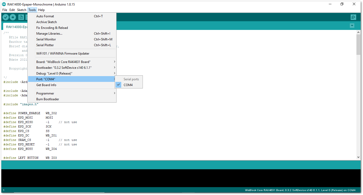 Figure 1: Selecting the correct Serial Port
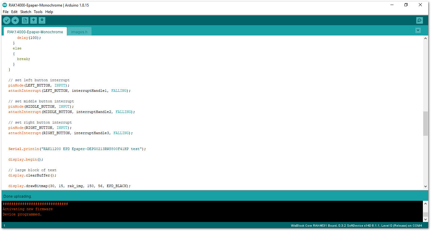 Figure 1: Uploading the RAK14000 example code
- Once you have successfully uploaded the example sketch, you should be able to see the image output on the E-Paper. You can also see the corresponding button pressed in the Serial Monitor.
RAK14000 in RAK11200 WisBlock Core Guide
Arduino Setup
If you already installed the RAKwireless Arduino BSP, the WisBlock Core and example code should now be available on the Arduino IDE.
- Select the WisBlock Core you have, as shown in Figure 16.
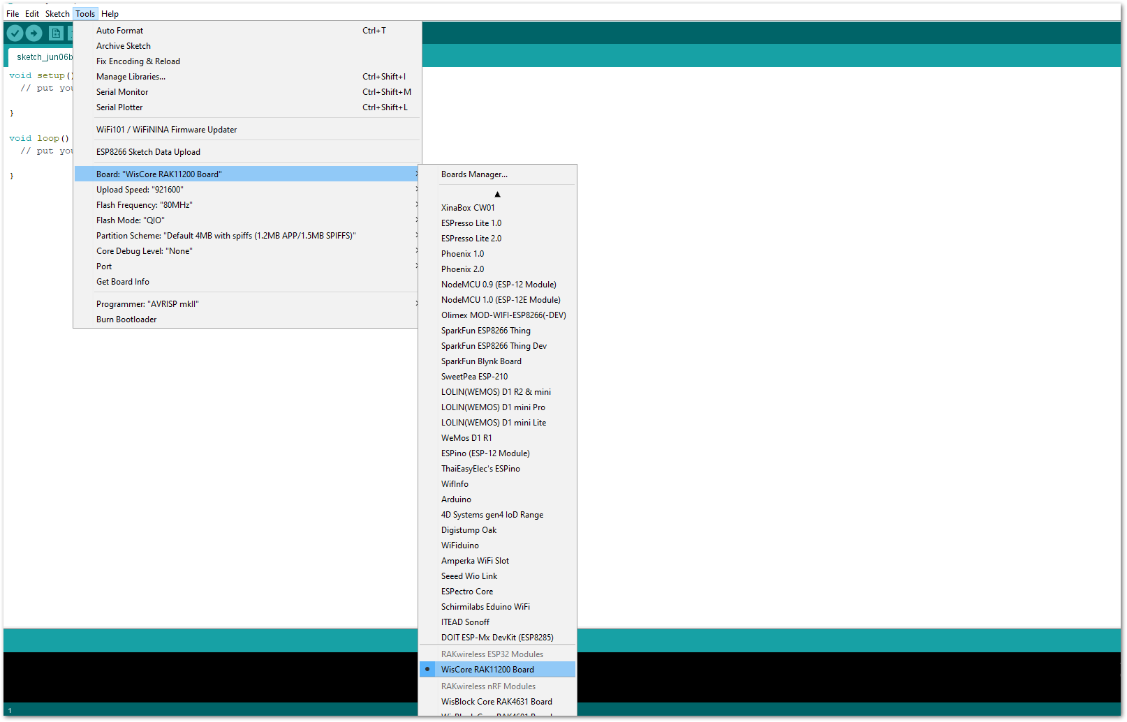 Figure 1: Selecting RAK11200 as WisBlock Core
- Install the Adafruit GFX Library.
- Open the Arduino IDE.
- On the Menu bar, click Sketch > Include Library > Manage Libraries.
- On the Library Manager text area, type adafruit gfx.
- To finish installation, click on Install button highlighted in yellow, as shown in Figure 17.
 Figure 1: Adafruit GFX Library Install
- Install Adafruit EPD Library
- Open the Arduino IDE.
- On the Menu bar, click Sketch > Include Library > Manage Libraries.
- On the Library Manager text area, type adafruit epd.
- To finish installation, click on Install button highlighted in yellow, as shown below in Figure 18.
 Figure 1: Adafruit EPD Library Install
- You can access the programming guide for the RAK14000 module by opening the example codes depending on your WisBlock Core, as shown in Figure 19.
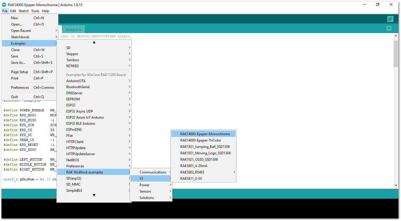 Figure 1: Opening RAK14000 example for RAK11200 WisBlock Core
You will need to change this section of the code depending on the E-Paper you are using.
// 2.13" EPD with SSD1680, width=250 pixels, heigh=122 pixels
Adafruit_SSD1680 display(250, 122, EPD_MOSI,EPD_SCK, EPD_DC, EPD_RESET,EPD_CS, SRAM_CS, EPD_MISO,EPD_BUSY);
- After opening the example code, you can now select the right port and upload the code, as shown in Figure 20 and Figure 22.
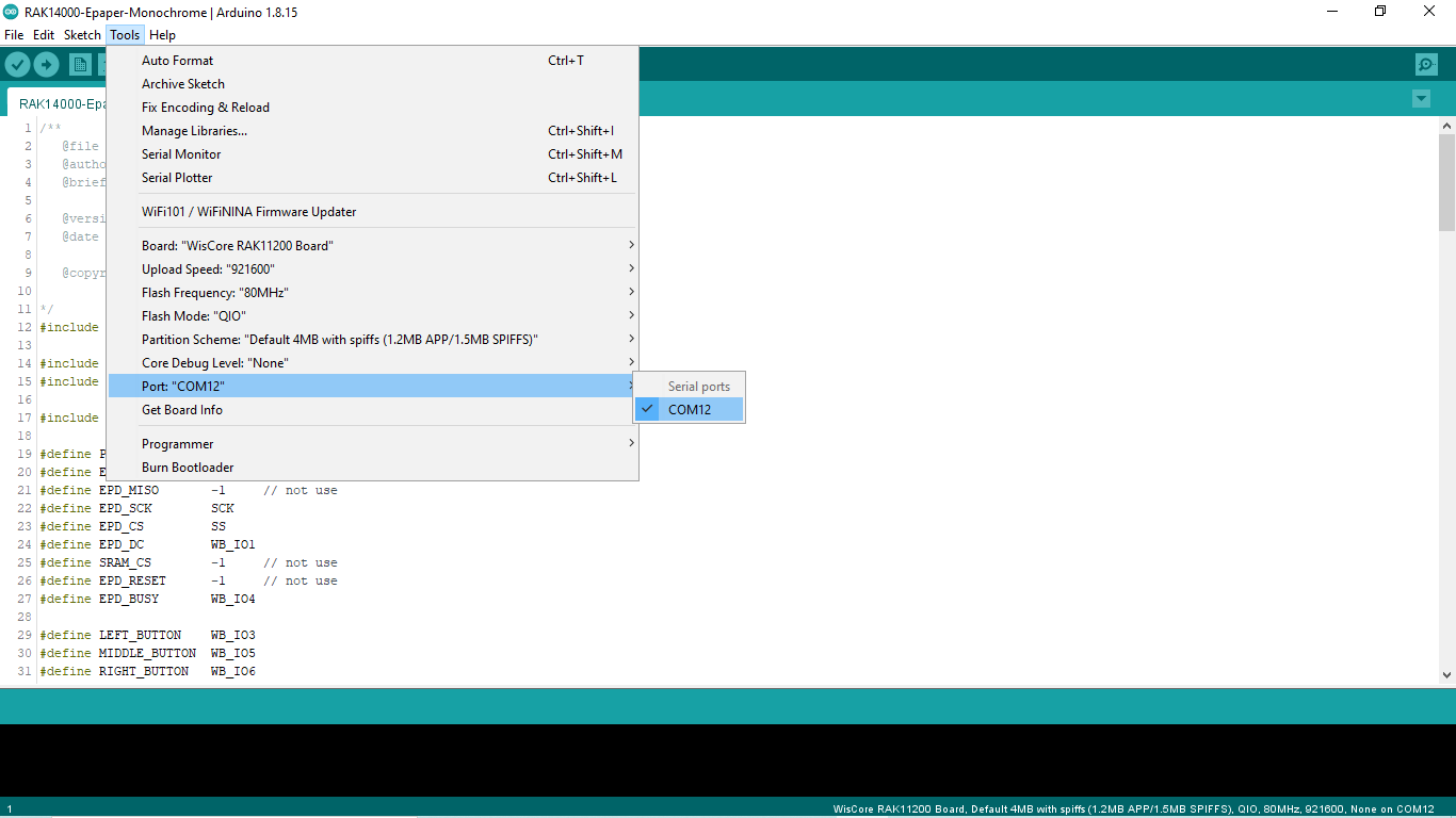 Figure 1: Selecting the correct Serial Port
Before uploading your sketch, short circuit BOOT0 and GND pins and press the reset button as shown below.
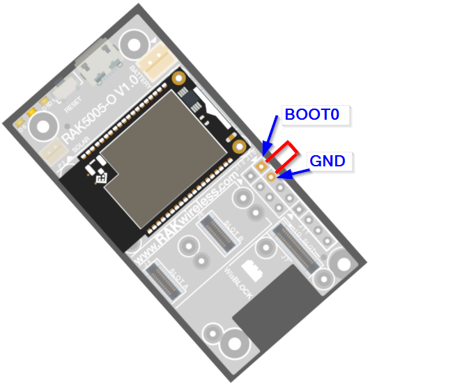 Figure 1: Force ESP32 Download mode
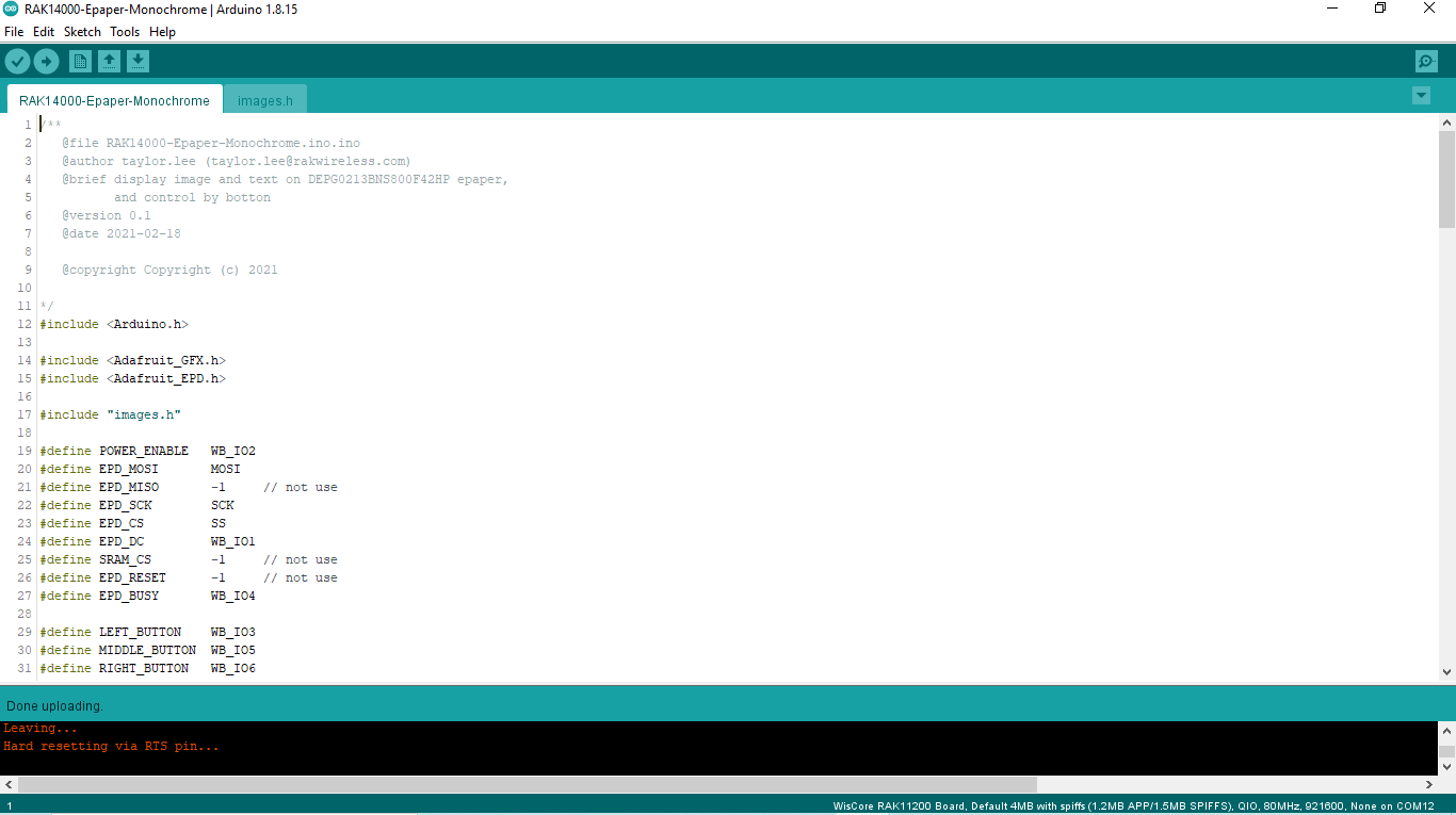 Figure 1: Uploading the RAK14000 example code
- Once you have successfully uploaded the example sketch, you should be able to see the image output on the E-Paper. You can also see the corresponding button pressed in the Serial Monitor.
RAK14000 in RAK11310 WisBlock Core Guide
Arduino Setup
If you already installed the RAKwireless Arduino BSP, the WisBlock Core and example code should now be available on the Arduino IDE.
- Select the RAK11310 WisBlock Core you have, as shown in Figure 23.
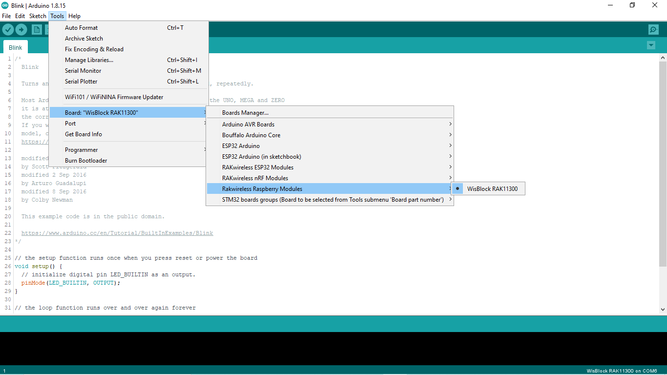 Figure 1: Selecting RAK11310 as WisBlock Core
- Install the Adafruit GFX Library.
- Open the Arduino IDE.
- On the Menu bar, click Sketch > Include Library > Manage Libraries.
- On the Library Manager text area, type adafruit gfx.
- To finish installation, click on the Install button highlighted in yellow, as shown in Figure 24.
 Figure 1: Adafruit GFX Library Install
- Install the Adafruit EPD Library.
- Open the Arduino IDE.
- On the Menu bar, click Sketch > Include Library > Manage Libraries.
- On the Library Manager text area, type adafruit epd.
- To finish installation, click on the Install button highlighted in yellow, as shown in Figure 25.
 Figure 1: Adafruit EPD Library Install
- You can access the programming guide for the RAK14000 module by opening the example codes, as shown in Figure 26.
There are two versions of RAK14000 module for sale in the RAKwireless Store, the white-black display panel and white-black-red display panel version.
You will need to change this section of the code depending on the E-Paper you are using.
typedef struct  DEPG {
   int  width;
   int  height;
   int  position1_x;
   int  position1_y;
   int  position2_x;
   int  position2_y;
   int  position3_x;
   int  position3_y;
   int  position4_x;
   int  position4_y;
} DEPG;

// DEPG  DEPG_HP = {250,122,40,20,40,30,40,50,90,40};  // use this for 250 x 122 white-black-red
DEPG  DEPG_HP = {212,104,30,15,30,25,30,45,80,30};  // use this for 212 x 104 white-black

Adafruit_SSD1680 display(DEPG_HP.width, DEPG_HP.height, EPD_MOSI,
                         EPD_SCK, EPD_DC, EPD_RESET,
                         EPD_CS, SRAM_CS, EPD_MISO,
                         EPD_BUSY);
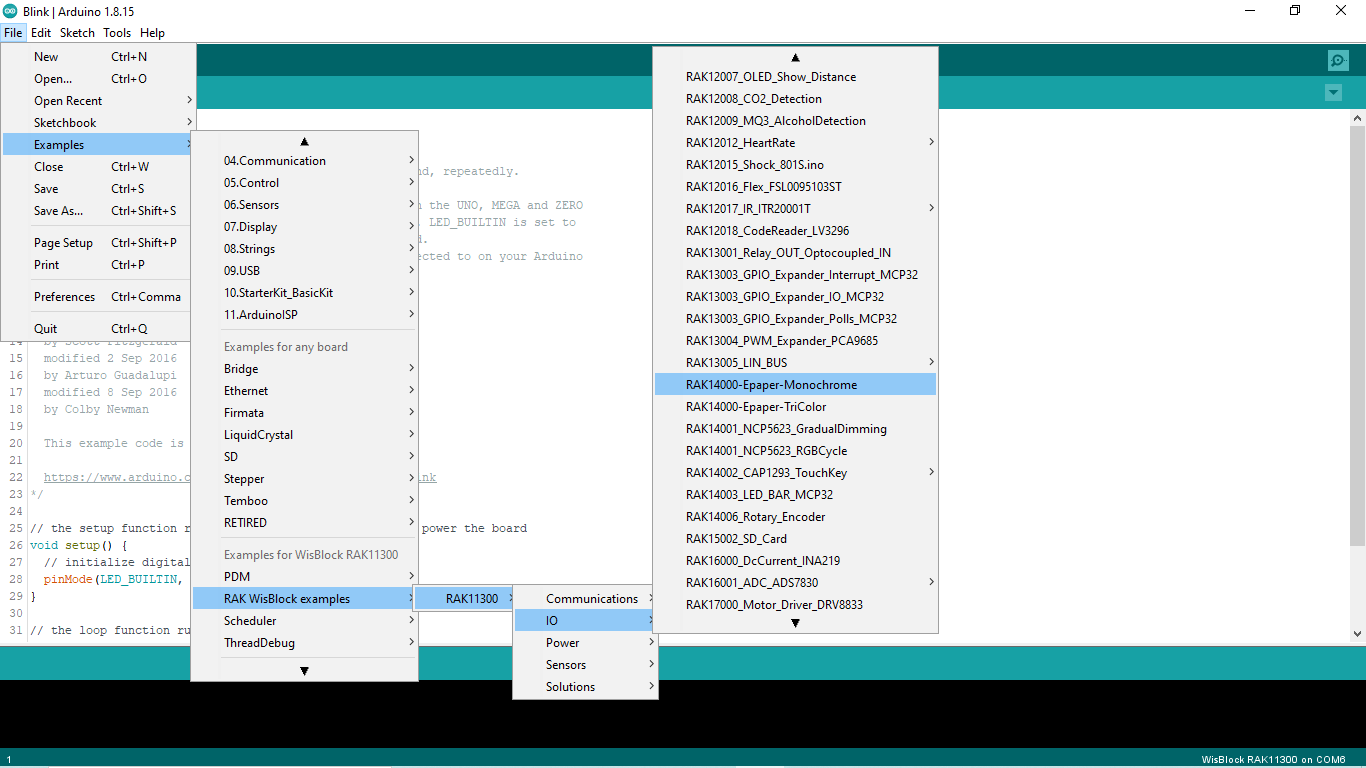 Figure 1: Opening RAK14000 example for RAK4631 WisBlock Core
- After opening the example code, you can now select the right port and upload the code, as shown in Figure 27 and Figure 28.
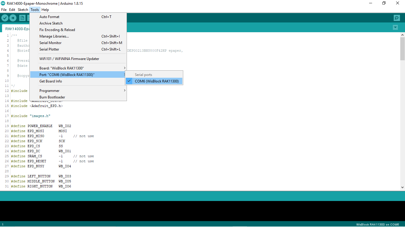 Figure 1: Selecting the correct Serial Port
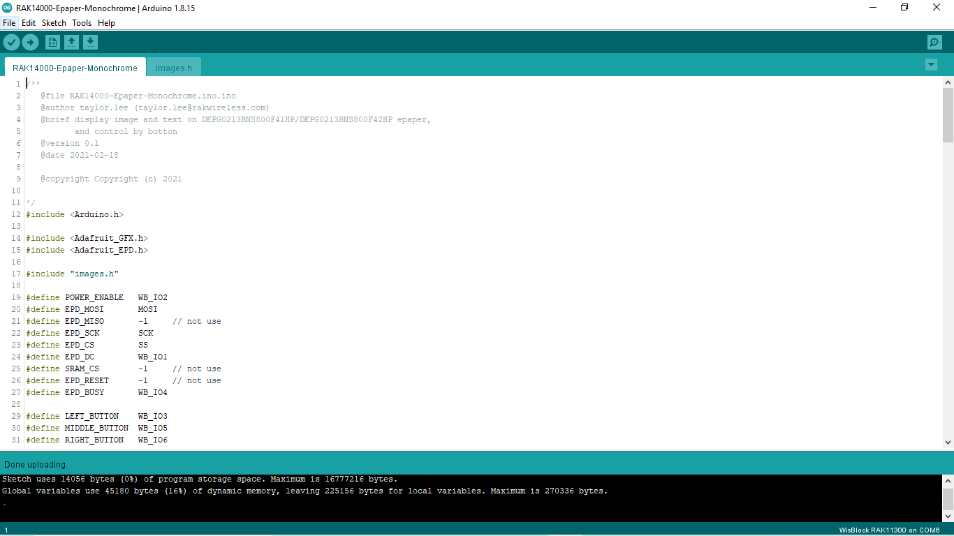 Figure 1: Uploading the RAK14000 example code
- Once you have successfully uploaded the example sketch, you should be able to see the image output on the E-Paper. You can also see the corresponding button pressed in the Serial Monitor.
