RAK14002 WisBlock Touch Sensor Module Quick Start Guide
Prerequisite
Product Inclusions
Before going through each and every step on using RAK14002 WisBlock Touch Sensor module, make sure to prepare the necessary items listed below:
Hardware
- RAK14002 WisBlock 3-channel Touchpad Module
- Your choice of WisBlock Base
- Your choice of WisBlock Core
- USB Cable
- Li-Ion/LiPo battery (optional)
- Solar charger (optional)
Software
- Download and install ArduinoIDE.
- To add the RAKwireless Core boards to your Arduino project, install the RAKwireless Arduino BSP. Follow the steps in the GitHub repo.
Product Configuration
Hardware Setup
RAK14002 module is part of the WisBlock Interface category and extends the WisBlock system with a 3-channel Capacitive Touch Sensor. The RAK14002 connects to the WisBlock Base Board through the IO slot. The Figure 1 shows the assembly of a WisBlock Core highlighted in green and the module RAK14002 highlighted in red. Also, always secure the connection of the WisBlock module by using the compatible screws. For more information about RAK14002, refer to the Datasheet.
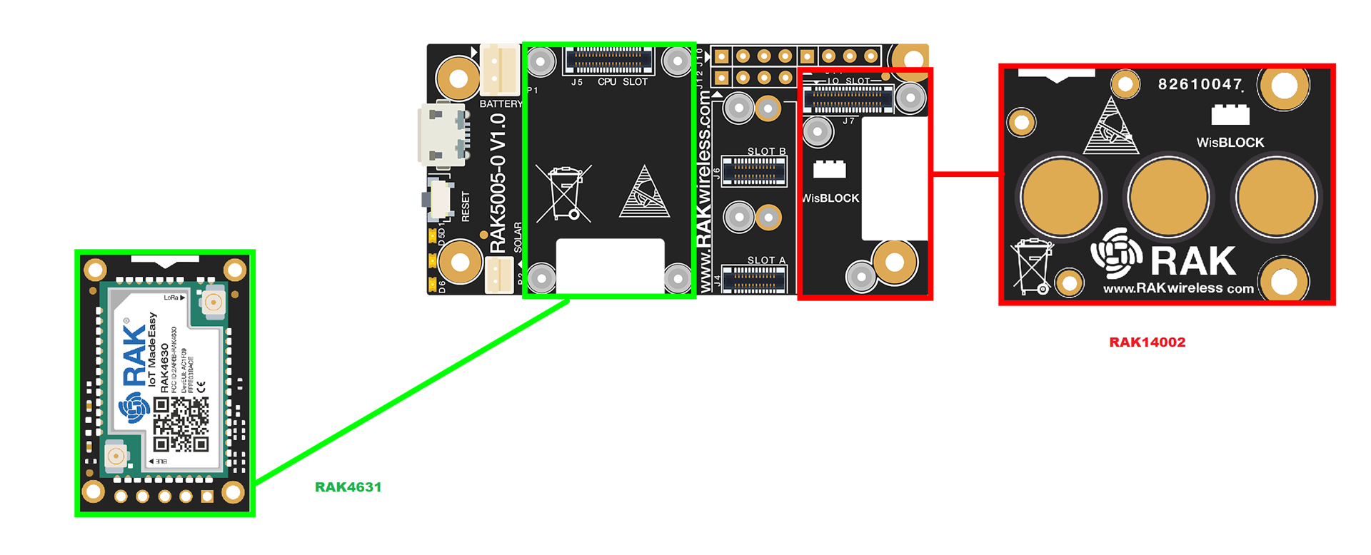 Figure 1: RAK14002 connection to WisBlock Base
Assembling and Disassembling of WisBlock Modules
Assembling
As shown in Figure 2, the location for the IO slot is properly marked by silkscreen. Follow carefully the procedure defined in RAK5005-O module assembly/disassembly instructions to attach a WisBlock module. Once attached, carefully fix the module with three pieces of M1.2 x 3 mm screws.
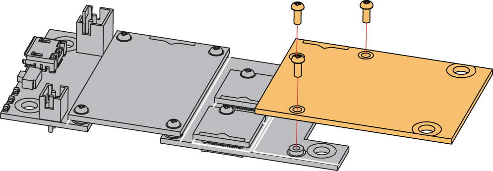 Figure 1: RAK14002 connection to WisBlock Base
Disassembling
The procedure in disassembling any type of WisBlock modules is the same.
- First, remove the screws.
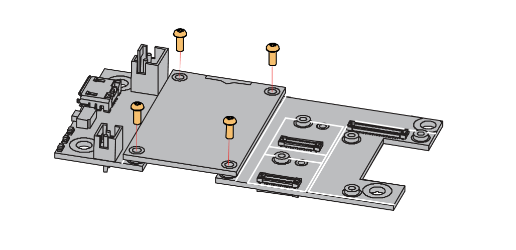 Figure 1: Removing screws from the WisBlock module
- Once the screws are removed, check the silkscreen of the module to find the correct location where force can be applied.
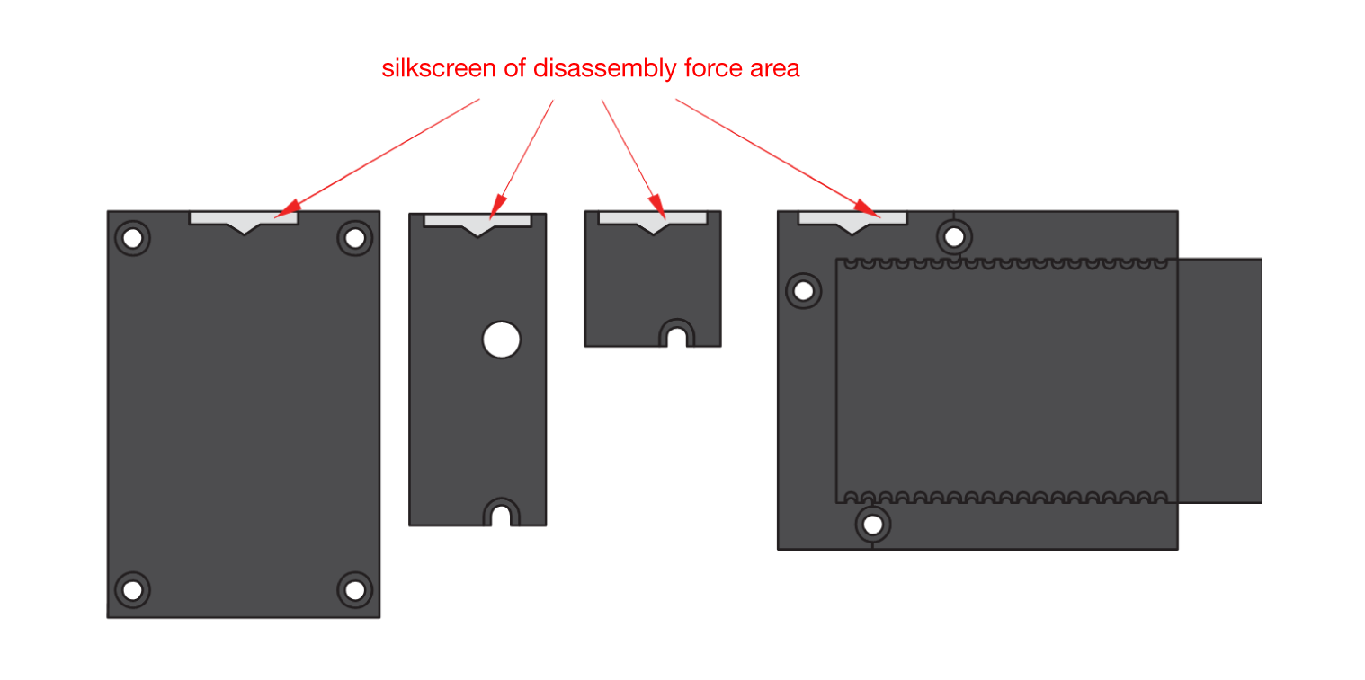 Figure 1: Detaching silkscreen on the WisBlock module
- Apply force to the module at the position of the connector, as shown in Figure 5, to detach the module from the baseboard.
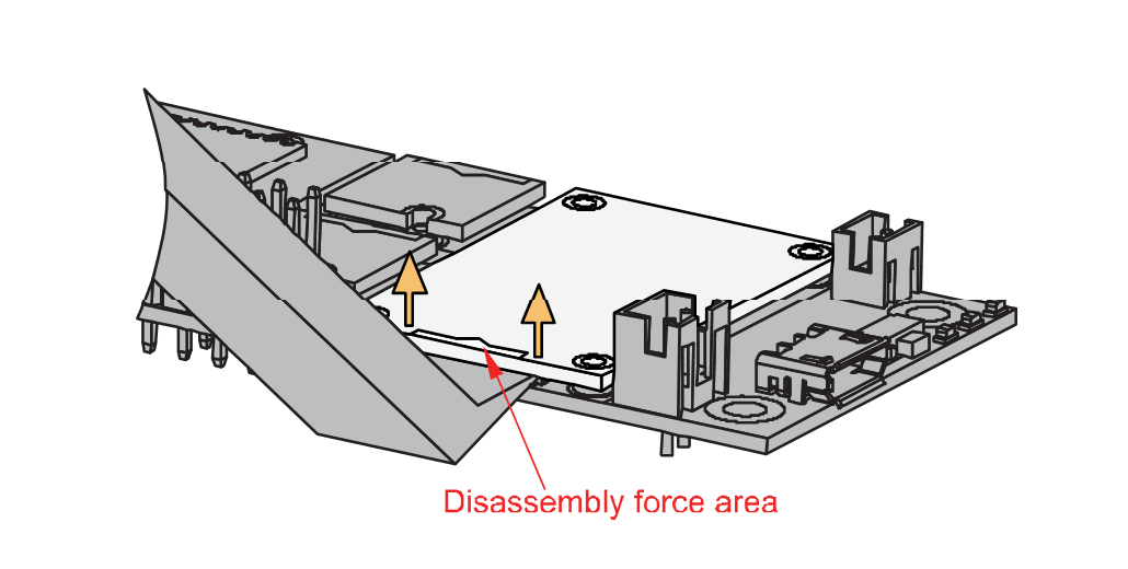 Figure 1: Applying even forces on the proper location of a WisBlock module
If you will connect other modules to the remaining WisBlock Base slots, check on the WisBlock Pin Mapper tool for possible conflicts. RAK14002 uses I2C and IO pins it can cause possible conflict especially on some IO modules.
After all this setup, you can now connect the battery and USB cable to start programming your WisBlock Core.
- Battery can cause harm if not handled properly.
- Only 3.7-4.2 V Rechargeable LiPo batteries are supported. It is highly recommended not to use other types of batteries with the system unless you know what you are doing.
- If a non-rechargeable battery is used, it has to be unplugged first before connecting the USB cable to the USB port of the board to configure the device. Not doing so might damage the battery or cause fire.
- Make sure the battery wires match the polarity on the RAK WisBlock Base Board. Not all batteries have the same wiring.
- Only 5 V solar panels are supported. Do not use 12 V solar panels. It will destroy the charging unit and eventually other electronic parts.
Software Configuration and Example
These are the quick links that go directly to the software guide for the specific WisBlock Core module you use.
- RAK14002 in RAK4631 WisBlock Core Guide
- RAK14002 in RAK11200 WisBlock Core Guide
- RAK14002 in RAK11310 WisBlock Core Guide
RAK14002 in RAK4631 WisBlock Core Guide
Arduino Setup
Install the RAKwireless Arduino BSP.
- Now select the RAK4631 WisBlock Core as shown in Figure 6.
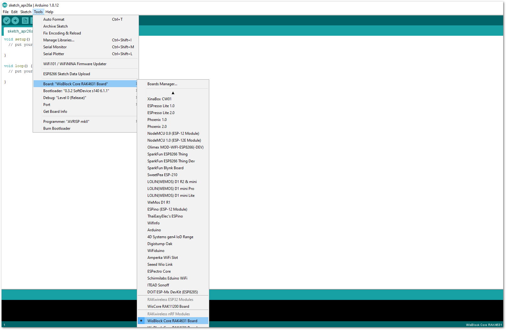 Figure 1: Select RAK4631 as WisBlock Core
Arduino programs are usually referred to as sketches. The sketches for this module will be available on the Arduino IDE after Library install.
- Install the RAKwireless CAP1293 Library using Arduino Library Manager.
On Arduino IDE select: Sketch-> Include Library -> Manage Libraries as shown in Figure 7.
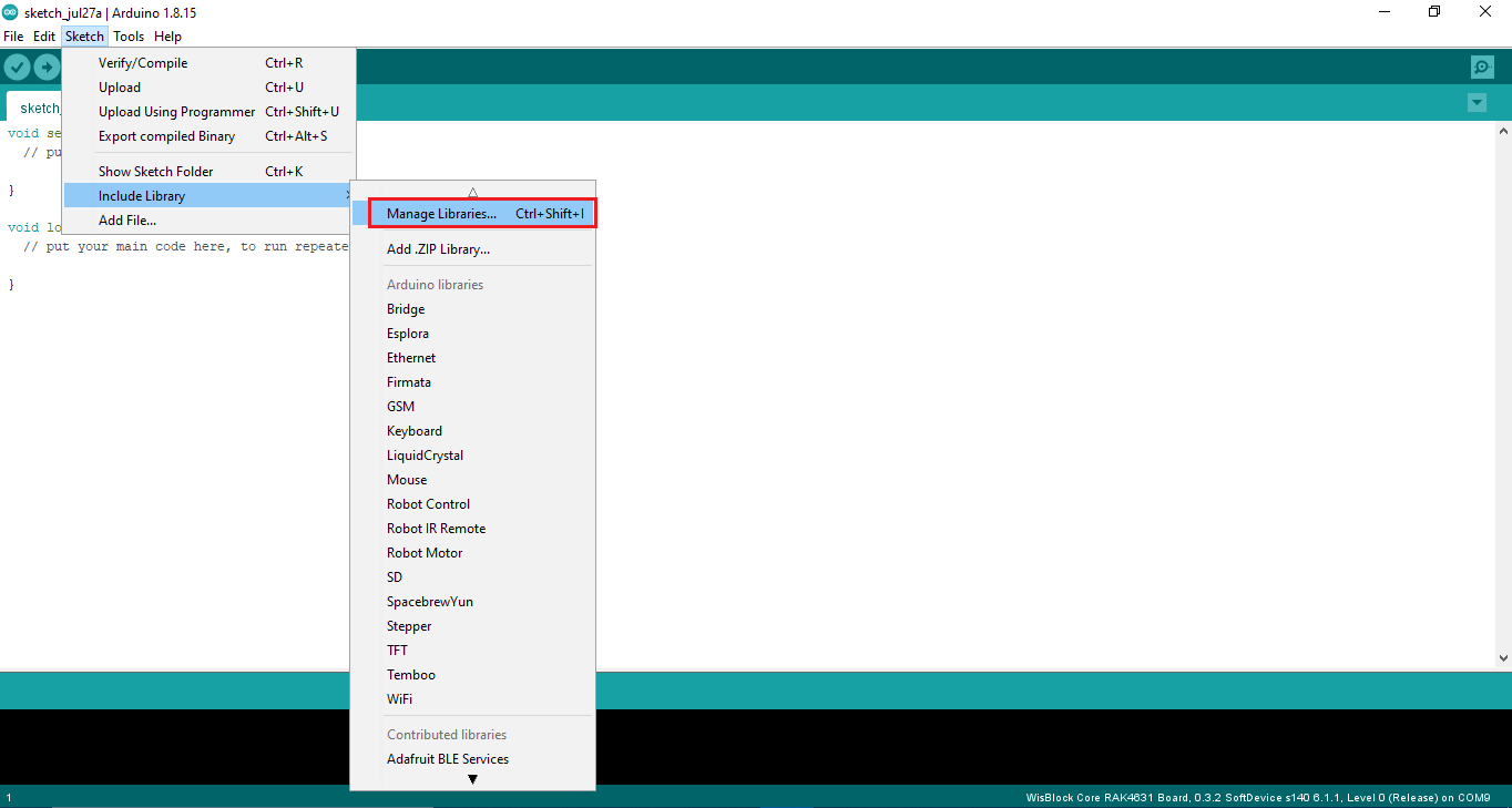 Figure 1: Select Arduino Library Manager
On Library Manager text area type RAKwireless CAP1293.
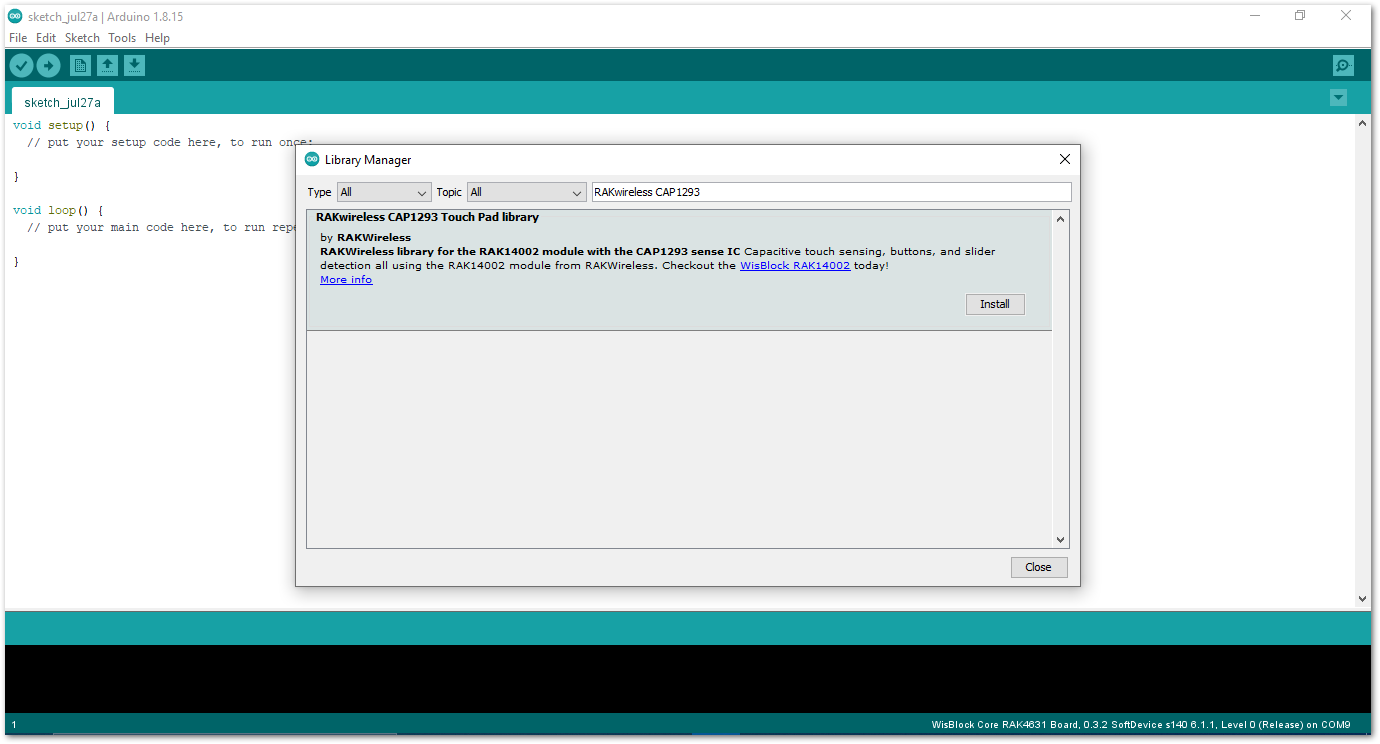 Figure 1: Arduino Library Manager RAKwireless CAP1293
To finish the installation, click on the Install button as shown in Figure 9.
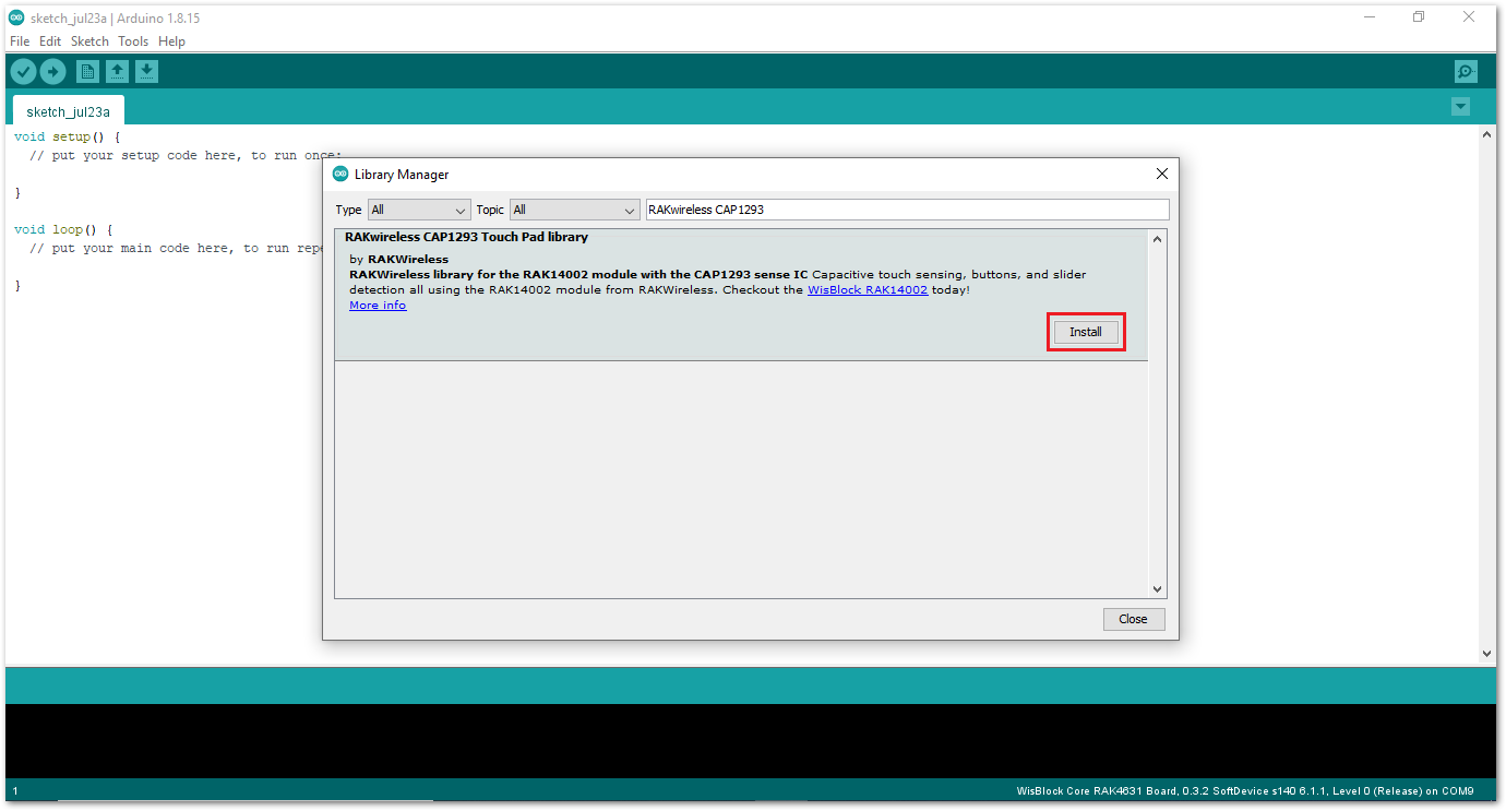 Figure 1: Finish RAKwireless CAP1293 Touch Pad Library Installation
- Once the library is installed, open the RAK14002 Example01_BasicReading example. On Arduino IDE select: File-> Examples -> RAKwireless CAP1293 Touch Pad Library -> RAK14002 Example01_BasicReading as shown in Figure 10.
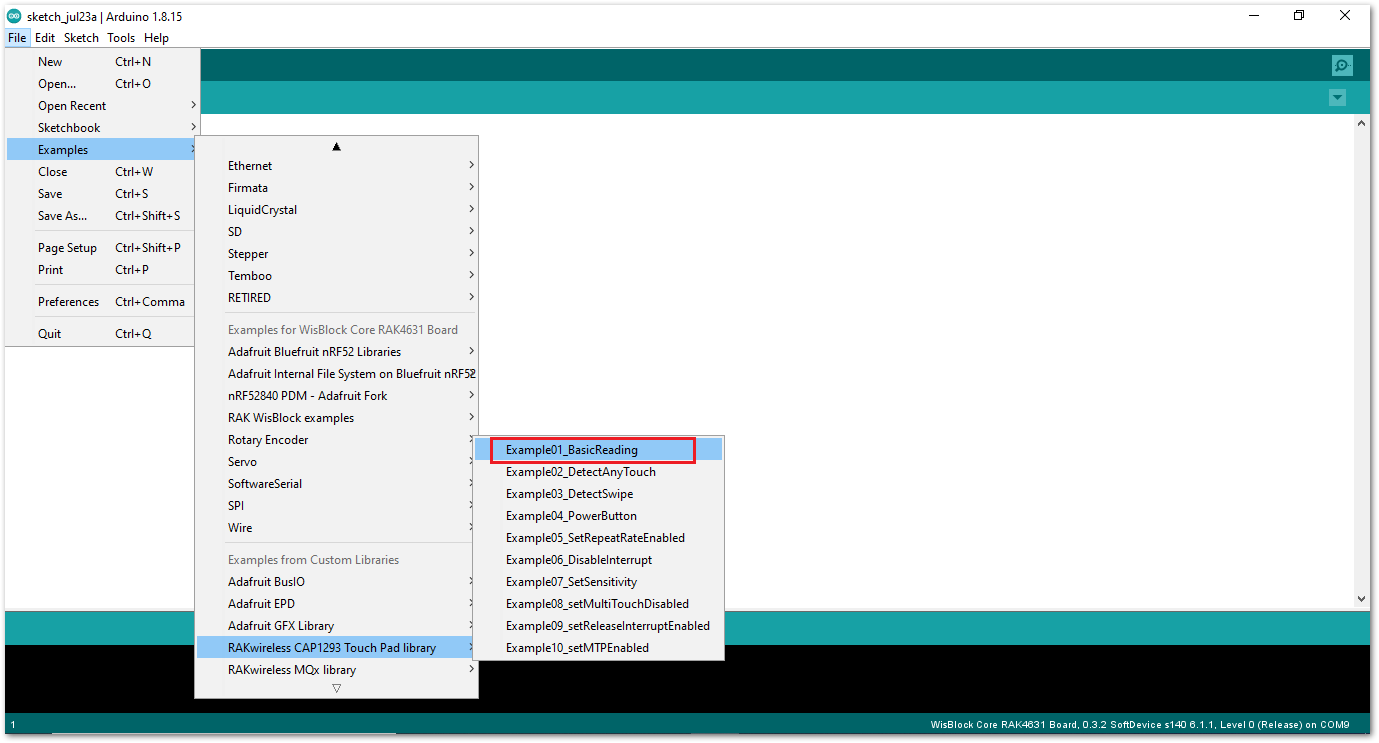 Figure 1: Open RAK14002 Example01_BasicReading Sketch
- You can now select the right serial port and upload the code, as shown in Figure 11 and Figure 12.
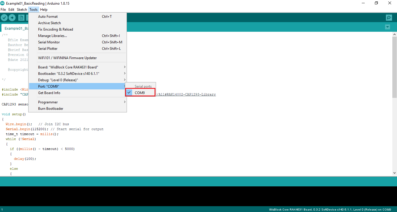 Figure 1: Selecting the correct Serial Port
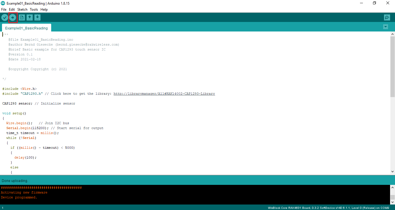 Figure 1: Uploading the RAK14002 example code on RAK4631
- When you successfully uploaded the Example01_BasicReading sketch, open the Serial Monitor of the Arduino IDE to check the sensor's reading logs.
Touch the left pad of the RAK14002 module. If you see the logs, as shown in Figure 13, then your RAK14002 is properly communicating to the WisBlock Core. The Connected! message means the I2C bus of RAK4631 WisBlock Core is connected to RAK14002.
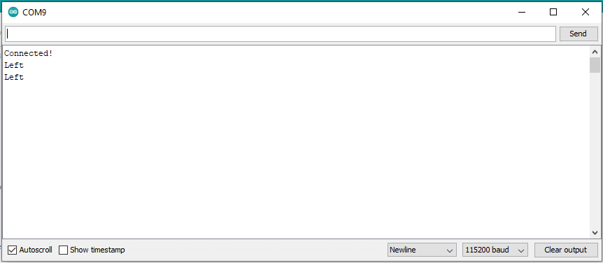 Figure 1: RAK14002 sensor data logs
PlatformIO Setup (Optional)
- Install the RAK_PATCH
After installing your RAK Core board on PlatformIO, you can import the entire project to PlatformIO.
- Import Arduino Project to PlatformIO.
- Open PlatformIO PIO Home and select Import Arduino Project, as shown in Figure 14.
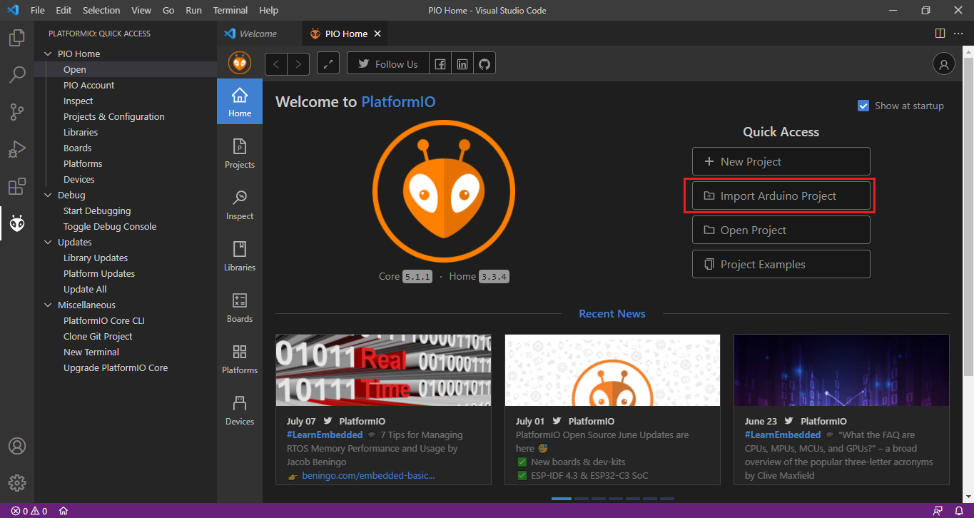 Figure 1: Import RAK14002 Arduino Project
- Select the WisBlock Core Board and check "Use Libraries installed by the Arduino IDE" option, as shown in Figure 15 below. Then choose the directory of the RAK14002 Arduino Project.
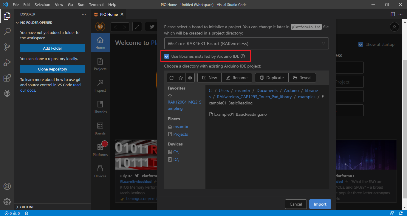 Figure 1: Select Board and check Import Libraries
- To finish import, click on Import button, as shown in Figure 16.
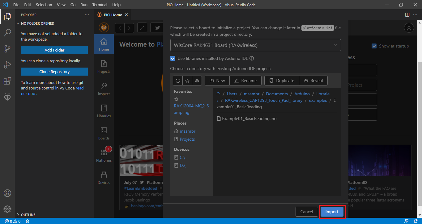 Figure 1: Select Board and check Import libraries
- Build imported project on PlatformIO.
- Now, you can build the project by clicking on highlighted icon, as shown in Figure 17.
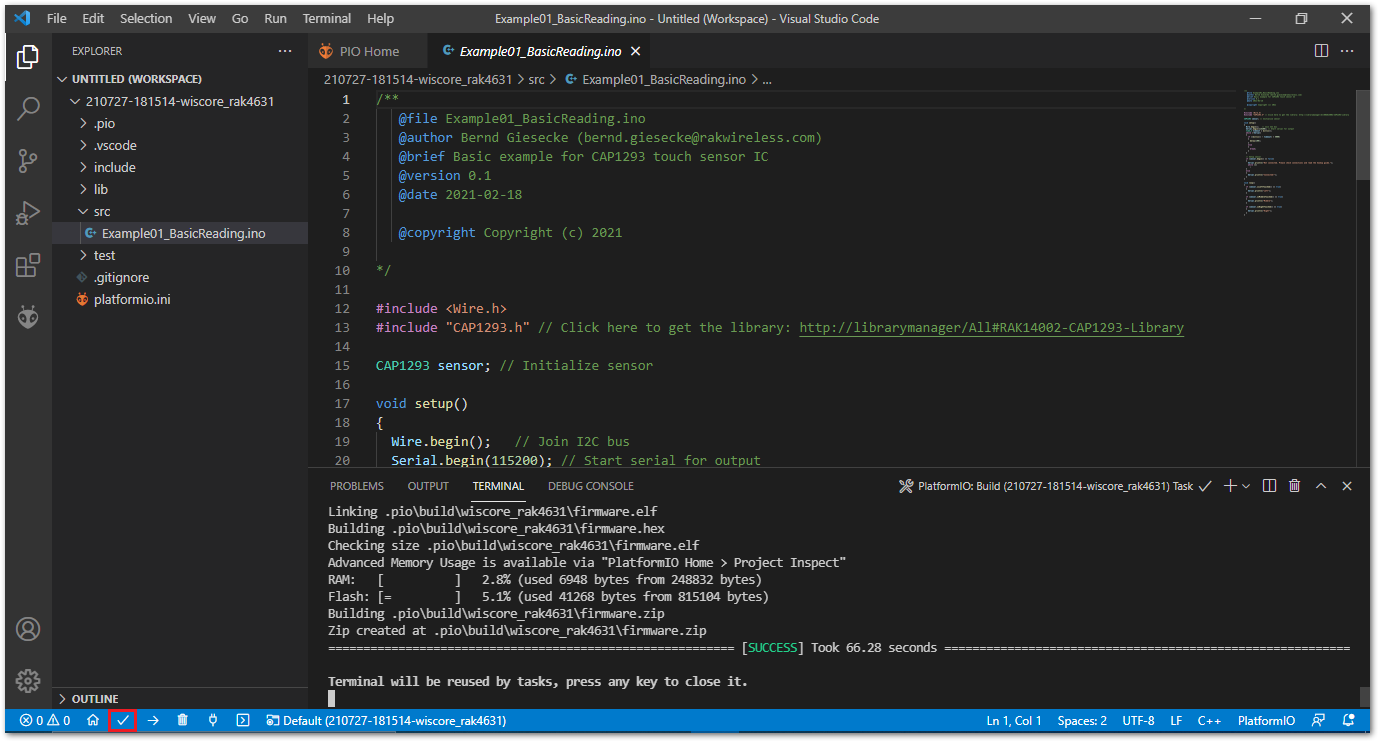 Figure 1: Build Arduino imported project
- Upload imported project on PlatformIO.
- To upload the project on target board, click on the highlighted icon, as shown in Figure 18.
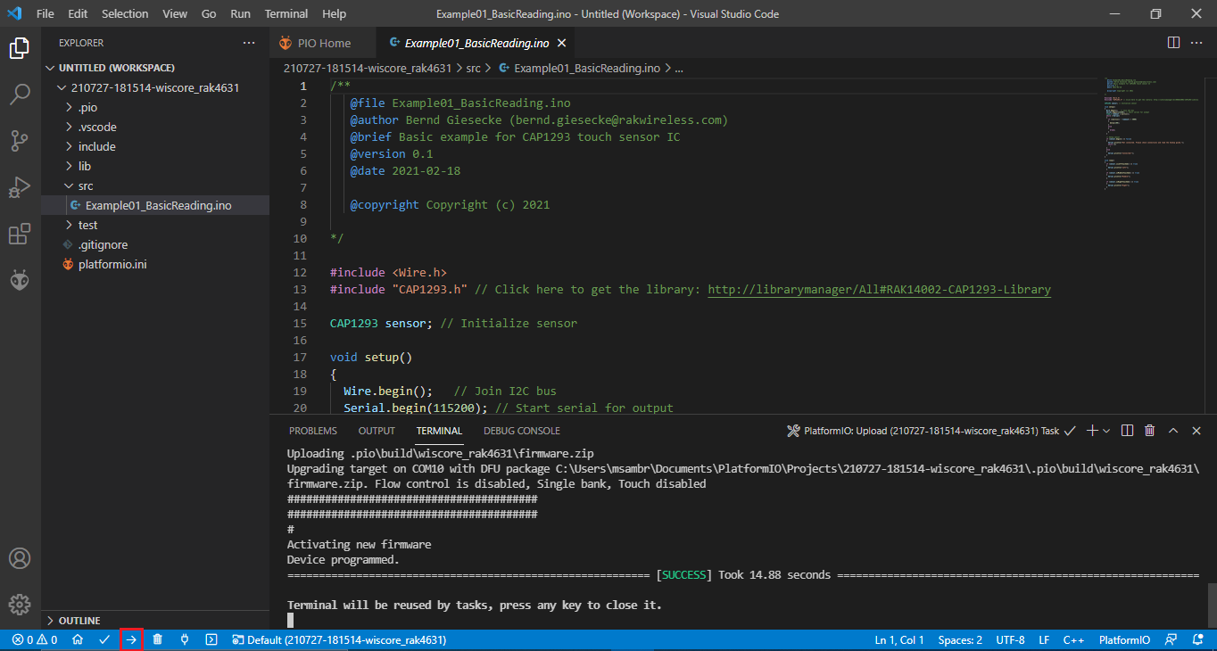 Figure 1: Upload Arduino imported project
RAK14002 in RAK11200 WisBlock Core Guide
Install the RAKwireless Arduino BSP.
- Select the RAK11200 WisBlock Core, as shown in Figure 19.
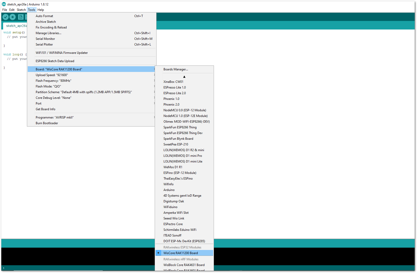 Figure 1: Select RAK11200 as WisBlock Core
Arduino programs are usually referred to as sketches. The sketches for this module will be available on the Arduino IDE after Library install.
- Install the RAKwireless CAP1293 Library using Arduino Library Manager.
- On Arduino IDE select: Sketch-> Include Library -> Manage Libraries, as shown in Figure 20.
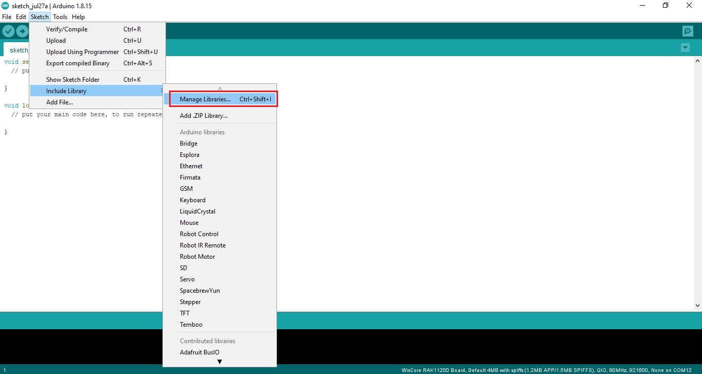 Figure 1: Select Arduino Library Manager
- On Library Manager text area, type RAKwireless CAP1293.
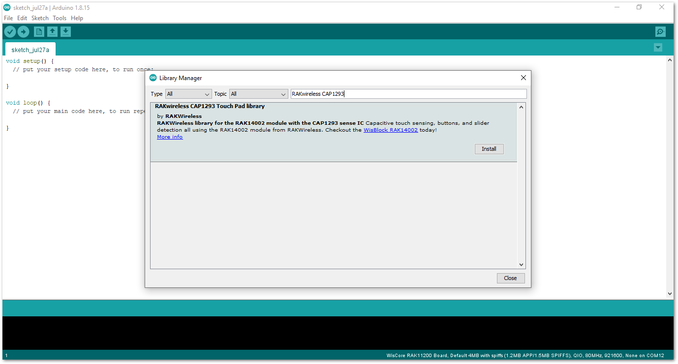 Figure 1: Arduino Library Manager RAKwireless CAP1293
- To finish the installation, click on the Install button as shown in Figure 22.
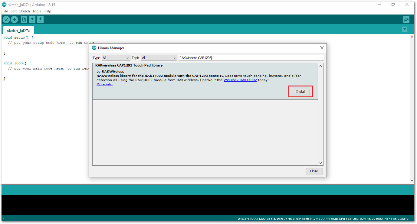 Figure 1: Finish RAKwireless CAP1293 Touch Pad Library Installation
- Once the library is installed, open the Example01_BasicReading example.
- On Arduino IDE select: File -> Examples -> RAK WisBlock Examples -> RAK11200 -> IO -> RAK14002_CAP1903_TouchKey -> Example01_BasicReading, as shown in Figure 23.
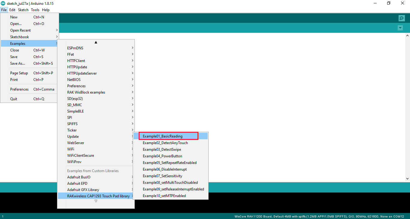 Figure 1: Open RAK14002 Example01_BasicReading Sketch
- You can now select the right serial port and upload the code, as shown in Figure 24 and Figure 25.
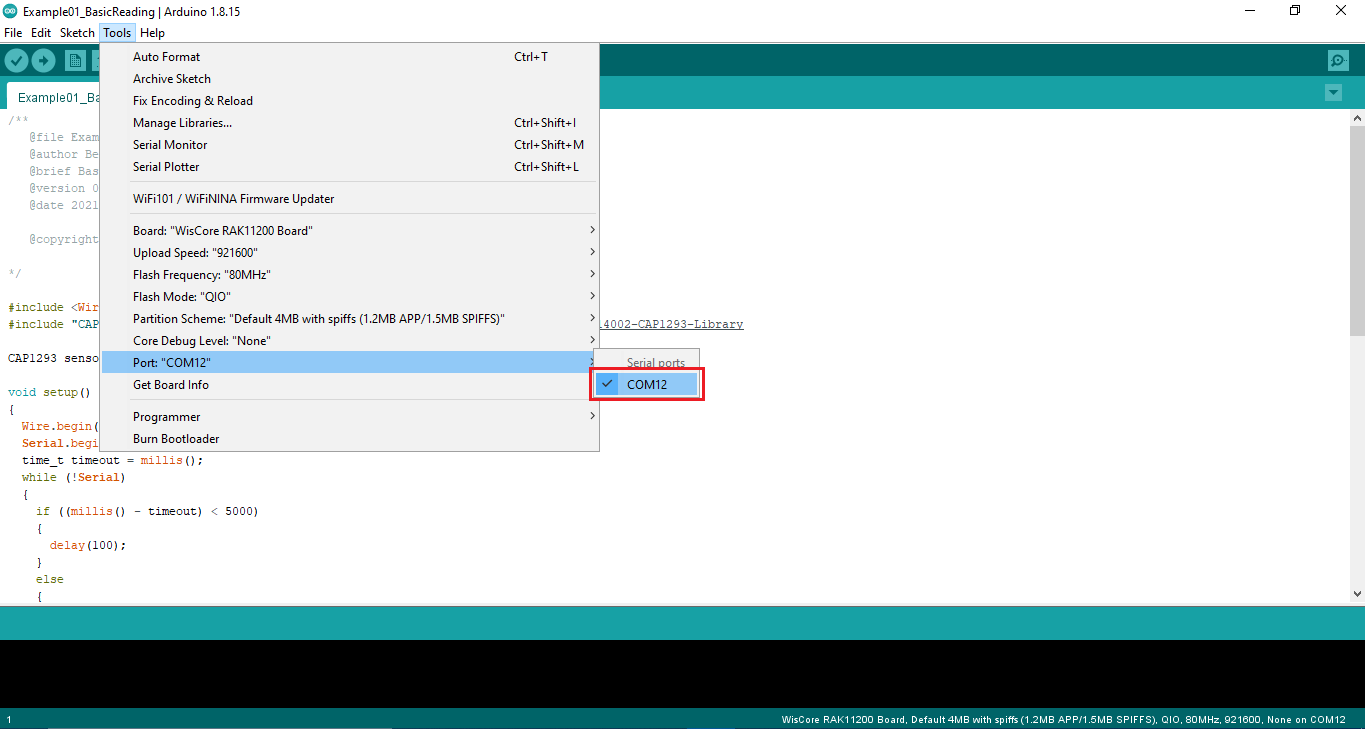 Figure 1: Selecting the correct Serial Port
RAK11200 requires BOOT0 pin to be configured properly first before uploading. If not done properly, uploading the source code to RAK11200 will fail. Check the full details on the RAK11200 Quick Start Guide.
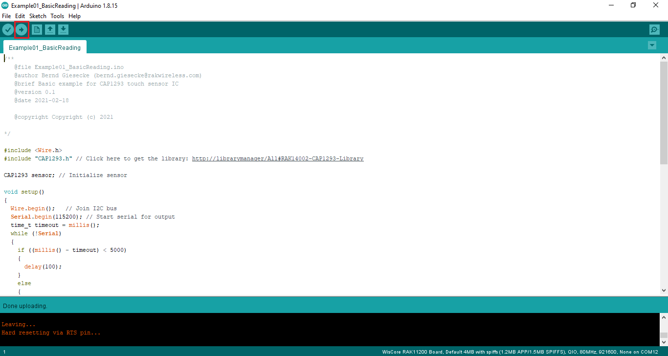 Figure 1: Uploading the RAK14002 example code on RAK11200
- When you successfully uploaded the Example01_BasicReading sketch, open the Serial Monitor of the Arduino IDE to check the sensor's reading logs.
Touch the left pad of the RAK14002 module. If you see the logs, as shown in Figure 26, then your RAK14002 is properly communicating to the WisBlock Core. The Connected! message means the I2C bus of RAK11200 WisBlock Core is connected to RAK14002.
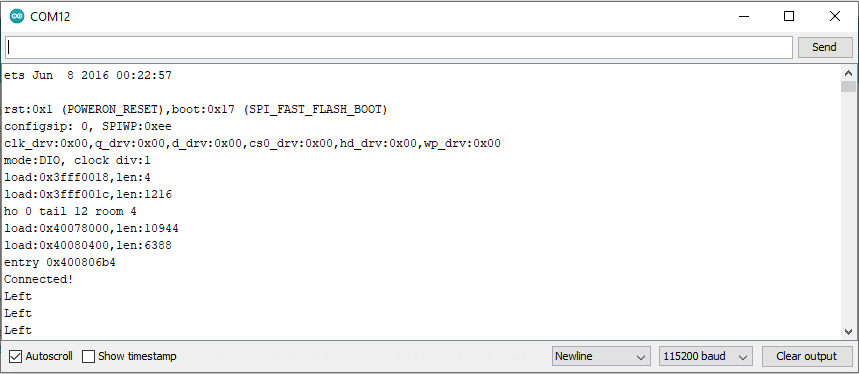 Figure 1: RAK14002 sensor data logs
RAK14002 in RAK11310 WisBlock Core Guide
Install the RAKwireless Arduino BSP.
- Launch Arduino IDE then select Tools-> Boards-> Boards Manager.
On Boards Manager text area, type RAK. The RAKwireless RP Boards will be shown in the window.
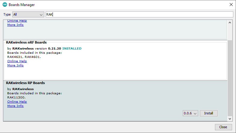 Figure 1: Boards Manager RAKwireless RP Boards
- Now select the RAKwireless RP Boards and then click on Install button, as shown in Figure 28.
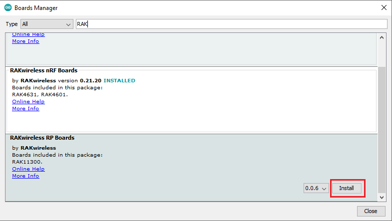 Figure 1: RAKwireless RP Boards install
Arduino programs are usually referred to as sketches. The sketches for this module will be available on the Arduino IDE after the Library install.
- Install the RAKwireless CAP1293 Library using Arduino Library Manager.
- Launch Arduino IDE and select: Sketch-> Include Library -> Manage Libraries, as shown in Figure 29.
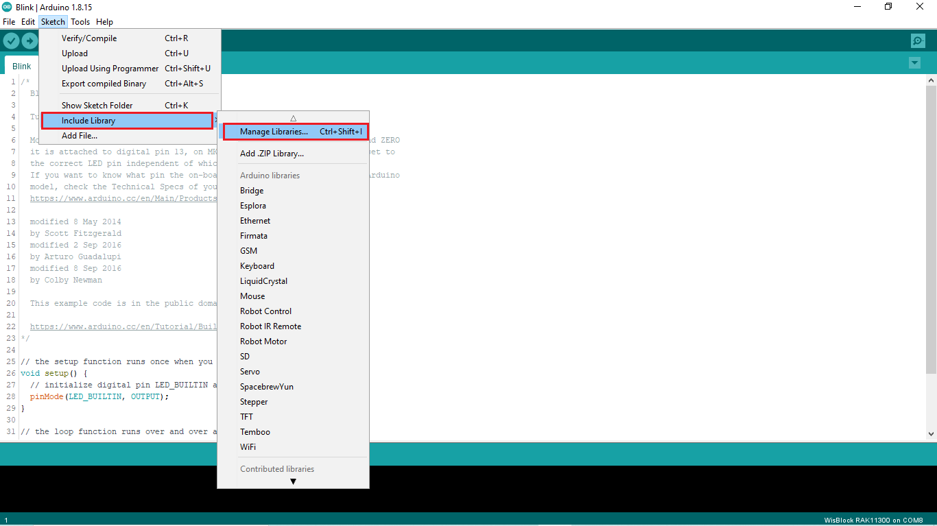 Figure 1: Select Arduino Library Manager
- On Library Manager text area, type RAKwireless CAP1293.
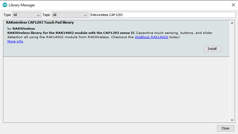 Figure 1: Arduino Library Manager RAKwireless CAP1293
- To finish the installation, click on the Install button, as shown in Figure 31.
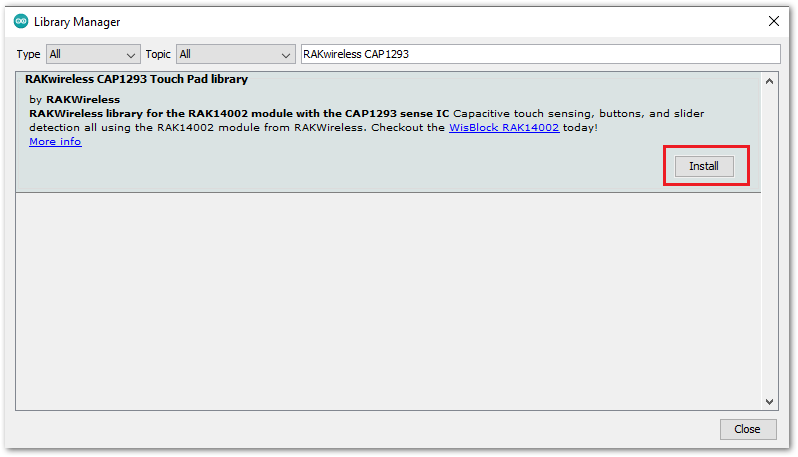 Figure 1: Finish RAKwireless CAP1293 Touch Pad Library Installation
- Once the library is installed, open the RAK14002 Example01_BasicReading example.
- Launch Arduino IDE and select: File -> Examples -> RAKwireless CAP1293 Touch Pad Library -> RAK14002 Example01_BasicReading, as shown in Figure 32.
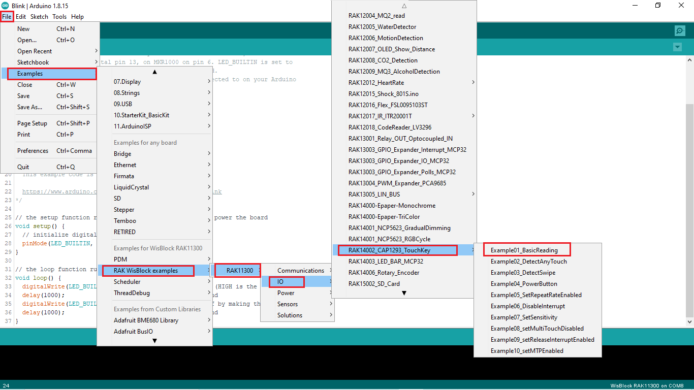 Figure 1: Open RAK14002 Example01_BasicReading
- You can now select the right serial port and upload the code, as shown in Figure 33 and Figure 34.
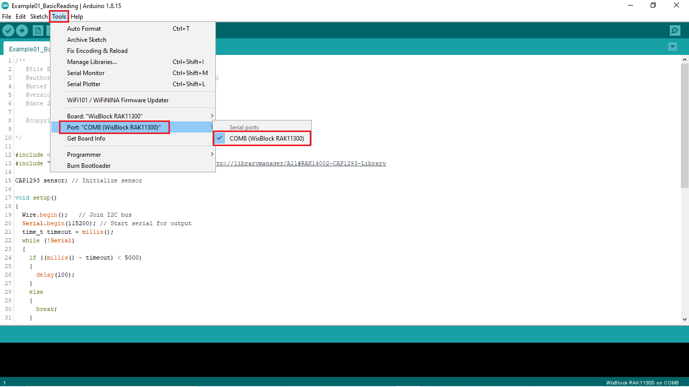 Figure 1: Selecting the RAK11310 Serial Port
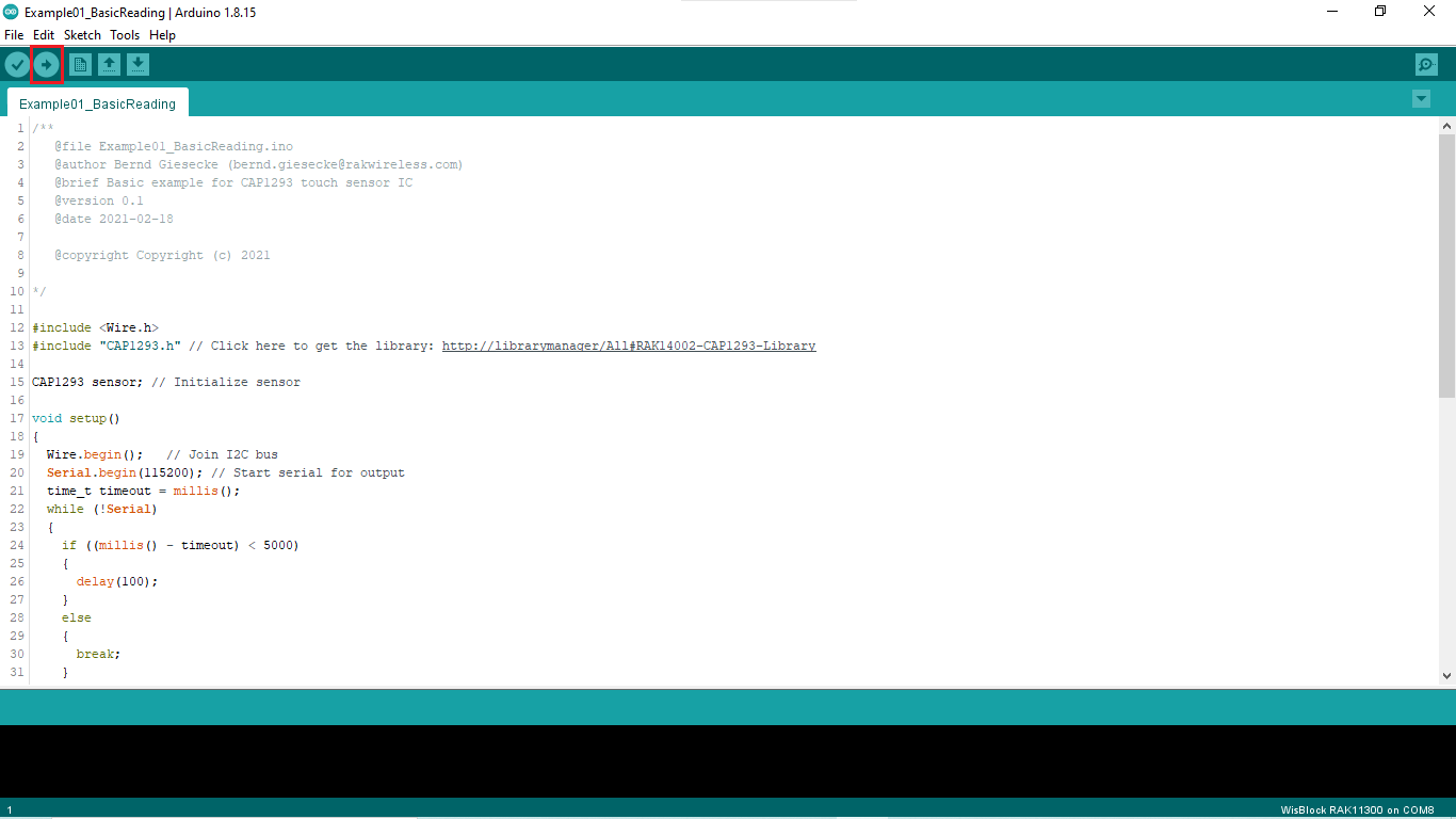 Figure 1: Uploading the RAK14002 example code on RAK11310
After successfully uploaded the Example01_BasicReading sketch, open the Serial Monitor of the Arduino IDE to check the sensor's reading logs.
RAK11310 PlatformIO Setup (Optional)
This procedure was tested only on Windows 10 and Ubuntu.
- First, install Raspberry Pi RP2040 platform.
- Launch Visual Studio Code and select the PIO Home tab (1). Then click on Platforms icon (2) and select the Embedded tab (3), as shown in Figure 35.
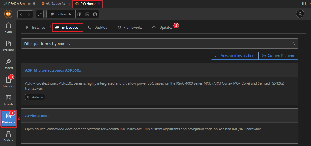 Figure 1: PIO Home PlatformIO platforms
- On Embedded text area, type Raspberry. To install the new platform, click on the new Raspberry PI RP2040 window.
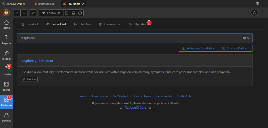 Figure 1: PIO Home Raspberry Pi RP2040
- Now click on Install button, as shown in Figure 37.
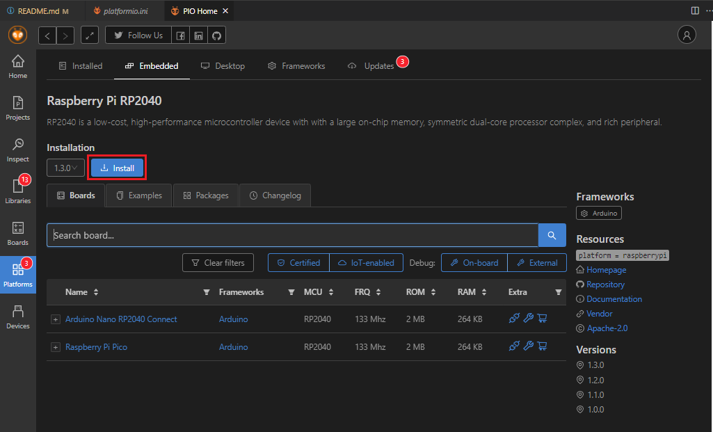 Figure 1: Raspberry PI RP2040 Platform install
- Open a project example that uses the RP2040 Platform.
- On the PIO Home tab, click on Project Examples.
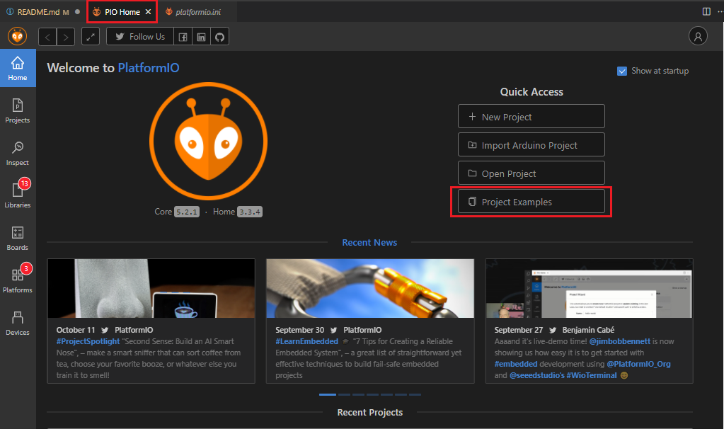 Figure 1: Import RP2040 project
- To find the RP2040 examples, type RP2040 on Import Project Example text area.
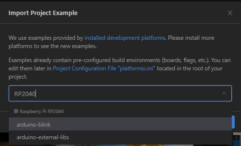 Figure 1: Selecting RP2040 project
- Choose arduino-blink project then click on Import button.
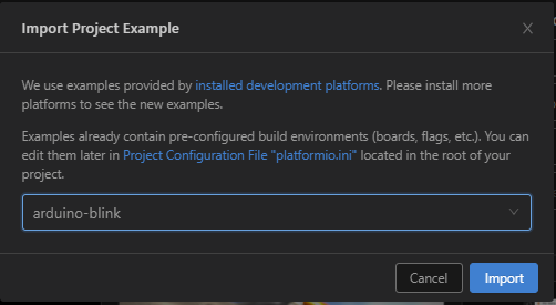 Figure 1: Import arduino-blink project
- Click Yes button on trust window.
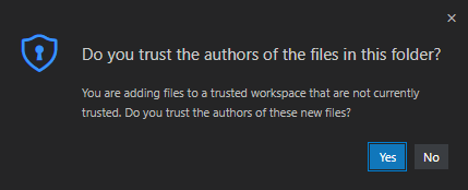 Figure 1: PlatformIO trust authors
-
Build the imported project and ignore warnings.
-
Install the RAK Patch.
-
Download and install the RAK Patch.
-
Unzip the contents of RAK_PATCH.zip into folder RAK_PATCH in your PlatformIO installation folder. The table below shows the PlatformIO installation directory for each operating system.
| PlatformIO path on different OS | |
|---|---|
| Windows 10 | %UserProfile%\.platformio\ |
| Linux | ~/.platformio/ |
| MacOS | /Users/{Your_User_id}/.platformio/ |
- Figure 42 shows the PlatformIO installation directory on Windows 10.
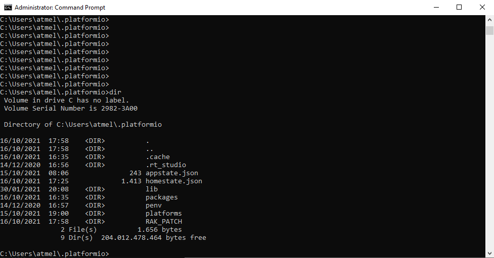 Figure 1: RAK patch folder on Windows
- Open a command prompt in
%UserProfile%.platformio\RAK_PATCHfolder and execute python./rak_patch.py.
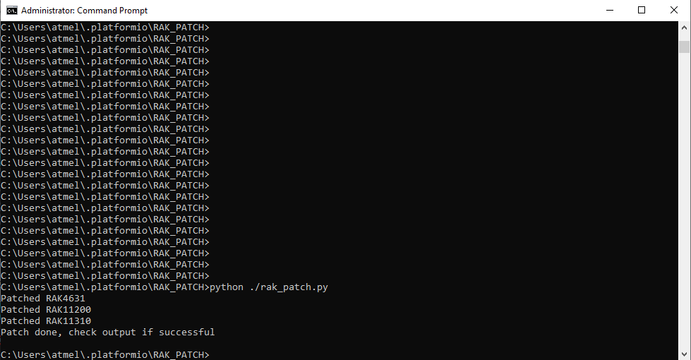 Figure 1: RAK patch installed on Windows
In case of Raspberry PI 2040 platform update on PlatformIO, the RAK_PATH script must be executed again after the platform update.
- Check RAK_PATCH installation.
- Select PIO Home tab, then click on + New Project button.
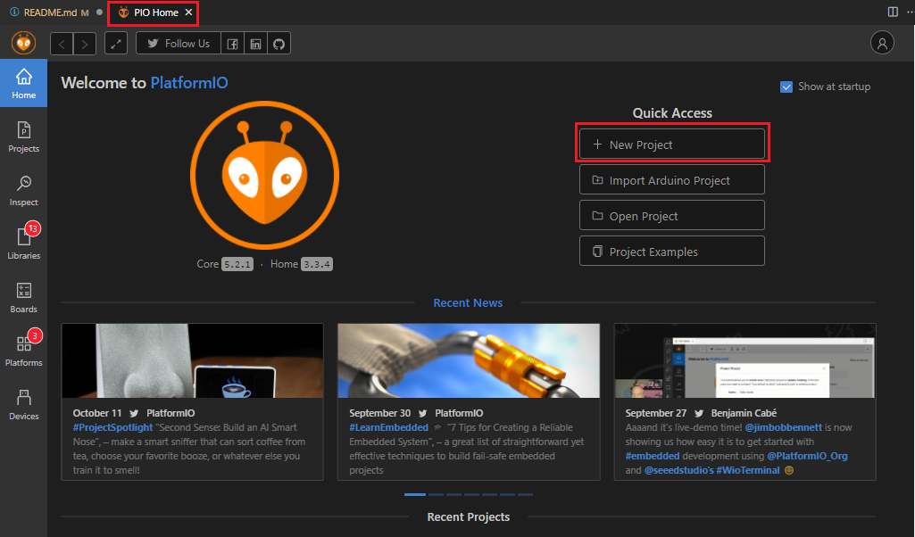 Figure 1: Create new PlatformIO project
-
A new Project Wizard window will appear.
-
Type RAK11300 on Board.
-
On the Name text area, type the name of your project.
-
To finish the project creation, click on Finish button.
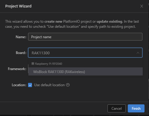 Figure 1: Project Wizard window
The board list for Raspberry Pi RP2040 Framework shows the WisBlock RAK11300 (RAKwireless).
