RAK14003 WisBlock LED Bar Graph Module Quick Start Guide
Prerequisite
What Do You Need?
Before going through each and every step on using the RAK14003 WisBlock module, make sure to prepare the necessary items listed below:
Hardware
- RAK14003 WisBlock LED Bar Graph Module
- Your choice of WisBlock Base
- Your choice of WisBlock Core
- USB Cable
- Li-Ion/LiPo battery (optional)
- Solar charger (optional)
Software
- Download and install ArduinoIDE.
- To add the RAKwireless Core boards on your Arduino board, install the RAKwireless Arduino BSP. Follow the steps in the GitHub repo.
Product Configuration
Hardware Setup
RAK14003 is an LED Bar Graph that is part of WisBlock Display modules. It consists of 10 configurable LEDs: five (5) green LEDs, three (3) yellow LEDs, and two (2) red LEDs. RAK14003 uses the MCP23017 from Microchip as an I/O Expander and KEM-102510A-RYG from Hongke Lighting as the LED bar. Each LED in the module can be controlled separately so the module can build a multipurpose graphic feedback display.
For more information about RAK14003, refer to the Datasheet.
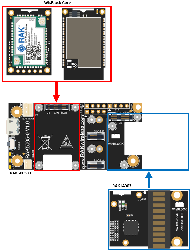 Figure 1: RAK14003 connection to WisBlock Base
Assembling and Disassembling of WisBlock Modules
Assembling
The RAK14003 module can be mounted on the IO slot of the WisBlock Base board, as shown in Figure 2. Also, always secure the connection of the WisBlock module by using compatible screws.
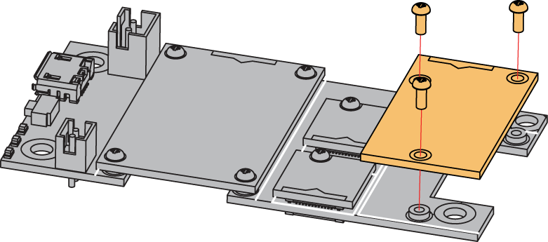 Figure 1: RAK14003 mounting connection to WisBlock Base module
Disassembling
The procedure in disassembling any type of WisBlock modules is the same.
- Remove the screws.
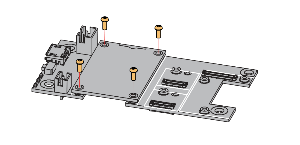 Figure 1: Removing screws from the WisBlock module
- Once the screws are removed, check the silkscreen of the module to find the correct location where force can be applied.
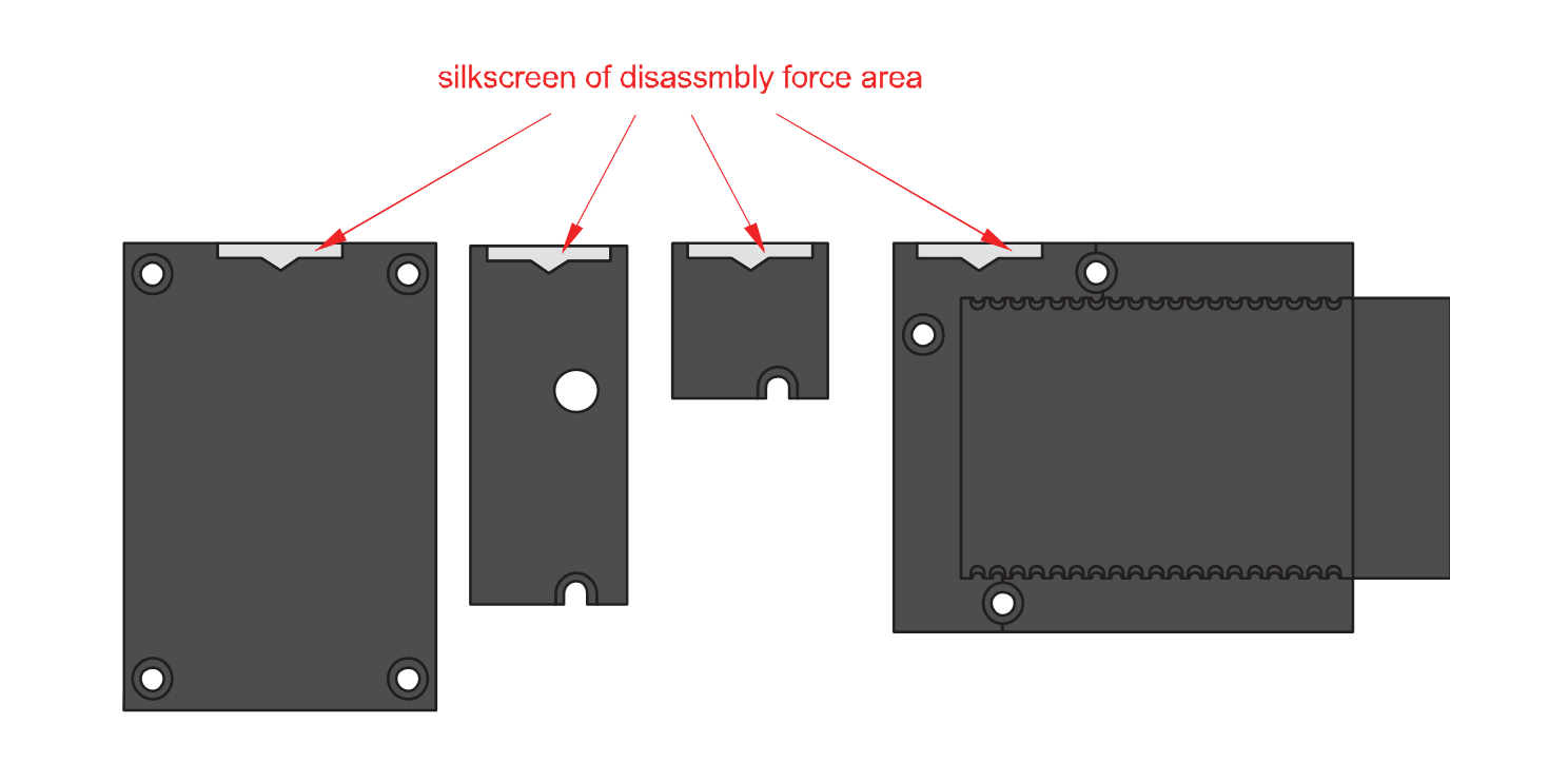 Figure 1: Detaching silkscreen on the WisBlock module
- Apply force to the module at the position of the connector, as shown in Figure 5, to detach the module from the baseboard.
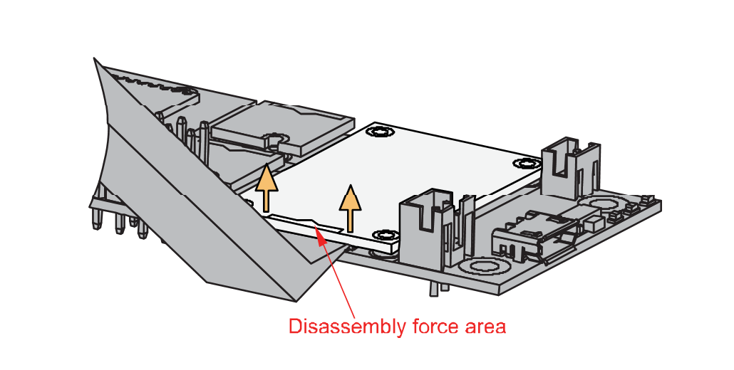 Figure 1: Applying even forces on the proper location of a WisBlock module
If you will connect other modules to the remaining WisBlock Base slots, check on the WisBlock Pin Mapper tool for possible conflicts. RAK14003 uses I2C communication lines, and it can cause possible conflict especially on some IO modules.
After all this setup, you can now connect the battery (optional) and USB cable to start programming your WisBlock Core.
Software Configuration and Example
Initial Test of the RAK14003 WisBlock Module
-
Install the RAKwireless Arduino BSP's for WisBlock by using the
package_rakwireless_index.jsonboard installation package, the WisBlock Core should now be available on the Arduino IDE. -
Select first the WisBlock Core you have, as shown in Figure 6 to Figure 8
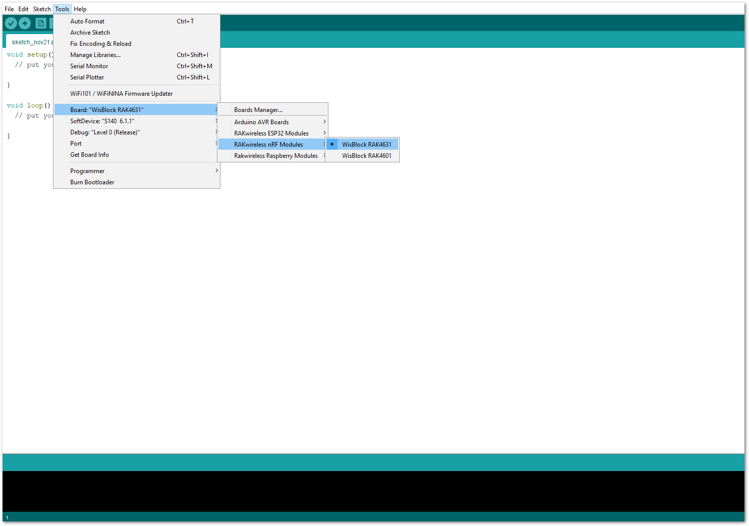 Figure 1: Selecting RAK4631 as WisBlock Core
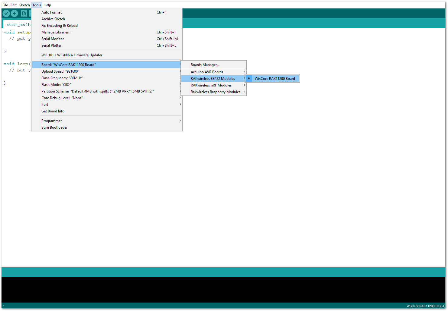 Figure 1: Selecting RAK11200 as WisBlock Core
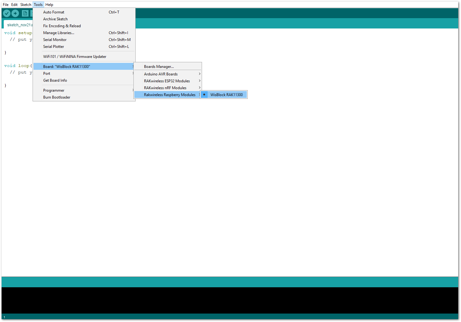 Figure 1: Selecting RAK11310 as WisBlock Core
- Copy the following sample code into your Arduino IDE.
/**
   @file RAK14003_LED_BAR_MCP32.ino
   @author rakwireless.com
   @brief Use MCP23017 to control LED Bar.
		Colour:2 Red, 3 Yellow, 5 Green
   @version 0.2
   @date 2022-5-11
   @copyright Copyright (c) 2022
**/
#include <Wire.h>
#include "Adafruit_MCP23X17.h"  //http://librarymanager/All#Adafruit_MCP23017

#define IIC_ADDRESS 0X24

Adafruit_MCP23X17 mcp;

void setup()
{
  pinMode(WB_IO2, OUTPUT);
  digitalWrite(WB_IO2, 1);

  // Reset device
  pinMode(WB_IO4, OUTPUT);
  digitalWrite(WB_IO4, 1);
  delay(10);
  digitalWrite(WB_IO4, 0);
  delay(10);
  digitalWrite(WB_IO4, 1);
  delay(10);

  mcp.begin_I2C(IIC_ADDRESS); // use default address 0.

  for(int i=0 ;i < 16 ;i++)
  {
    mcp.digitalWrite(i, HIGH);  // Turn off all LEDs.
    mcp.pinMode(i, OUTPUT);     // Set pins as output.
  }
}

void loop()
{
  int i;
  for(i=0 ;i < 10 ;i++)
  {
    mcp.digitalWrite(i, LOW);
    delay(200);
  }
  for(i=0 ;i < 10 ;i++)
  {
    mcp.digitalWrite(9-i, HIGH);
    delay(200);
  }
  for(i=0 ;i < 10 ;i++)
  {
    mcp.digitalWrite(i, LOW);
  }
  delay(300);
  for(i=0 ;i < 10 ;i++)
  {
    mcp.digitalWrite(i, HIGH);
  }
  delay(300);
}
If you experience any error in compiling the example sketch, check the updated code for your WisBlock Core Module that can be found on the RAK14003 WisBlock Example Code Repository and this sample code in Github will work on all WisBlock Core.
- Once the example code is open, install the Adafruit MCP23017 library by clicking the yellow highlighted link, as shown in Figure 9 and Figure 10.
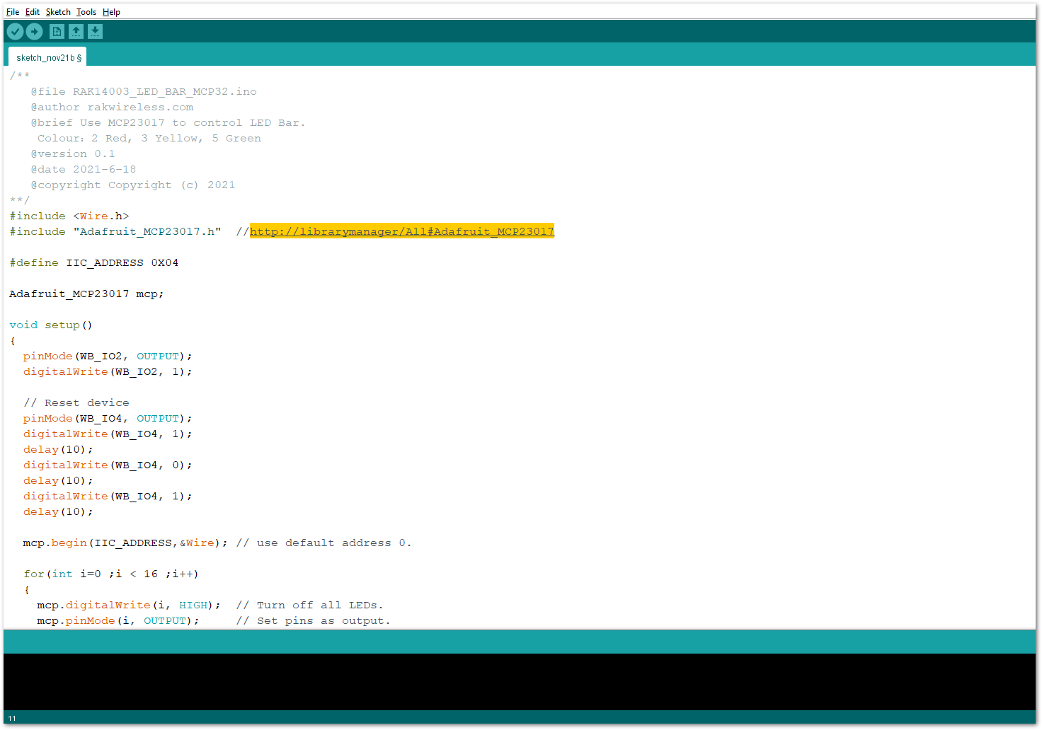 Figure 1: Accessing the library used for RAK14003 Module
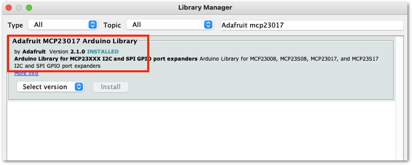 Figure 1: Installing the compatible library for RAK14003 Module
The library version required must be at least ver 2.1.0 to compile the example code successfully.
- After successful installation of the library, you can now select the right serial port and upload the code, as shown in Figure 11 and Figure 12.
If you're using the RAK11200 as your WisBlock Core, the RAK11200 requires the Boot0 pin to be configured properly first before uploading. If not done properly, uploading the source code to RAK11200 will fail. Check the full details on the RAK11200 Quick Start Guide.
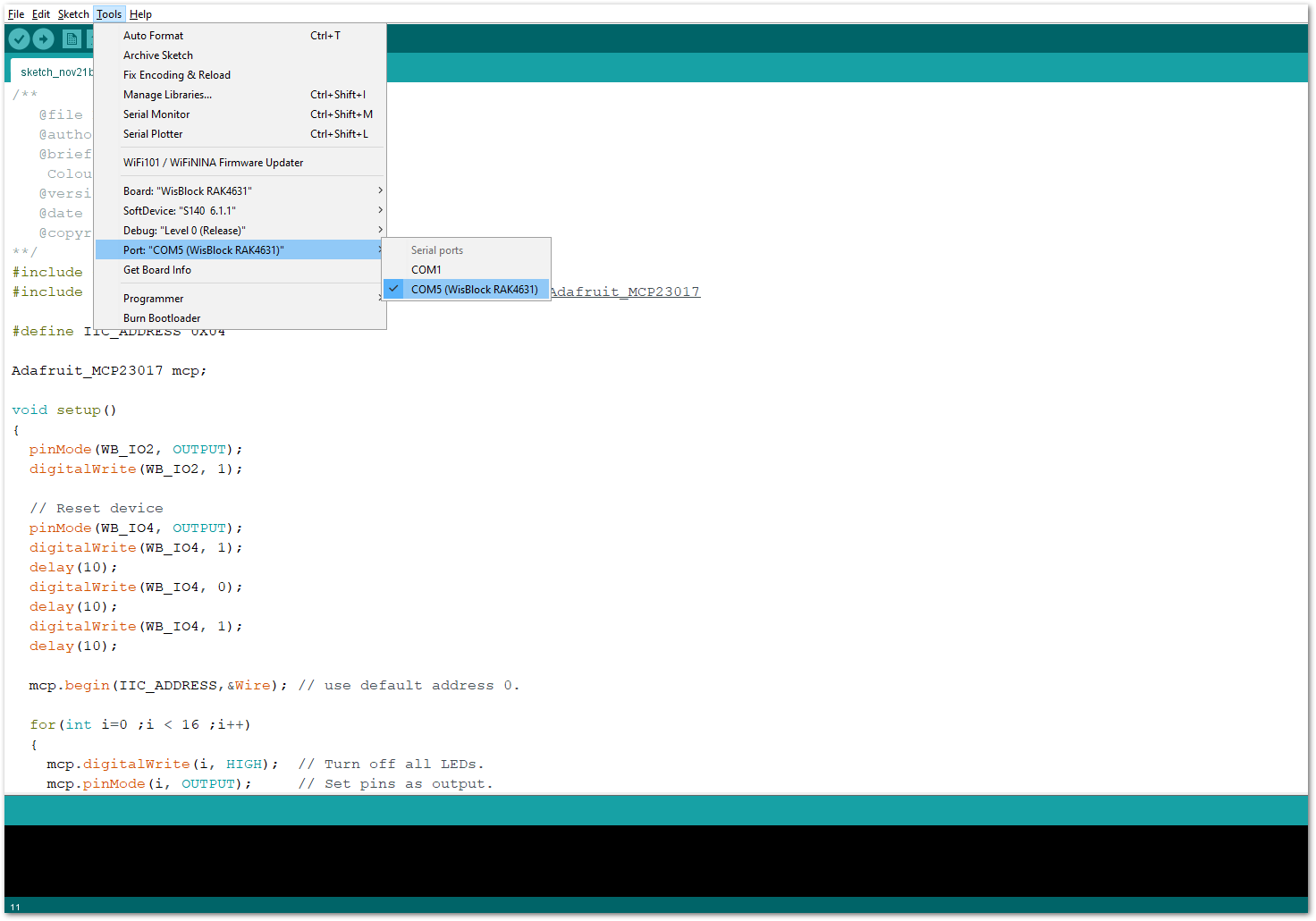 Figure 1: Selecting the correct Serial Port
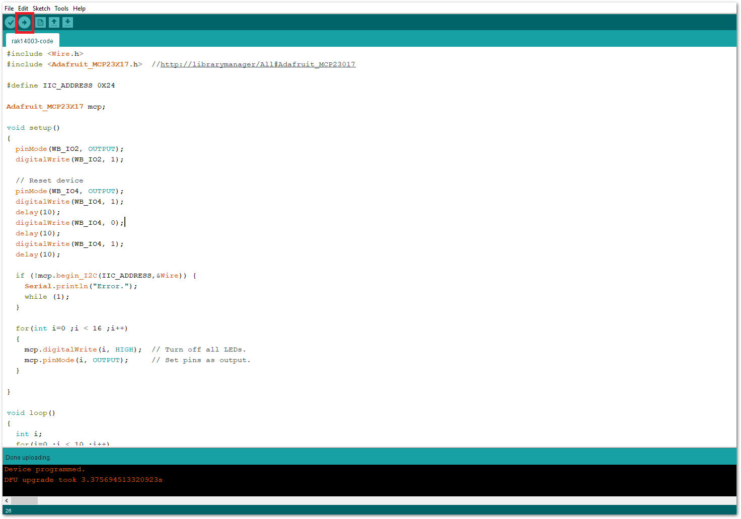 Figure 1: Uploading the RAK14003 example code
- When you successfully uploaded the example sketch, you'll see that the LED Bar Graph module lights up in incrementing and decrementing way as shown below. Therefore, your RAK14003 is properly communicating to the WisBlock core.
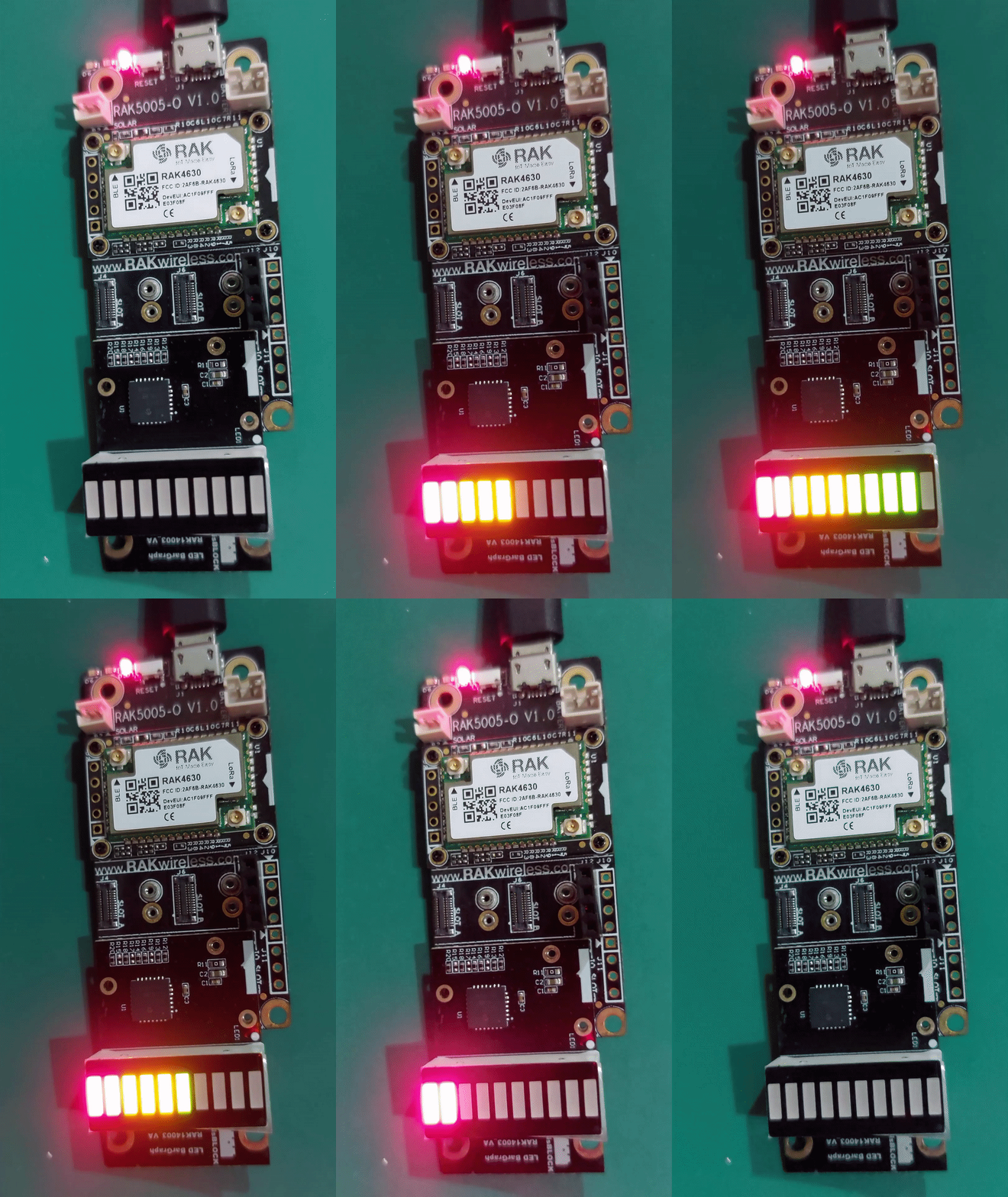 Figure 1: RAK14003 LED Bar Graph