RAK14004 WisBlock Keypad Module Quick Start Guide
Prerequisite
Product Inclusions
Before going through each and every step on using the RAK14004 WisBlock module, make sure to prepare the necessary items listed below:
Hardware
- RAK14004 Wisblock WisBlock Keypad Module
- Your choice of WisBlock Base
- Your choice of WisBlock Core
- Your choice of WisBlock Keypad
- USB Cable
- Li-Ion/LiPo battery (optional)
- Solar charger (optional)
Software
- Download and install Arduino IDE.
- To add the RAKwireless Core boards on your Arduino Boards Manager, install the RAKwireless Arduino BSP.
Product Configuration
Hardware Setup
Assembling and Disassembling of WisBlock Modules
Assembling
The RAK14004 module is designed as an IO extension module that allows to add a keypad and create a customized IoT solution. For more information about RAK14004, refer to the Datasheet.
The RAK14004 module can be mounted on the IO slot of the WisBlock Base Board, as shown in Figure 1. Also, always secure the connection of the WisBlock module by using compatible screws.
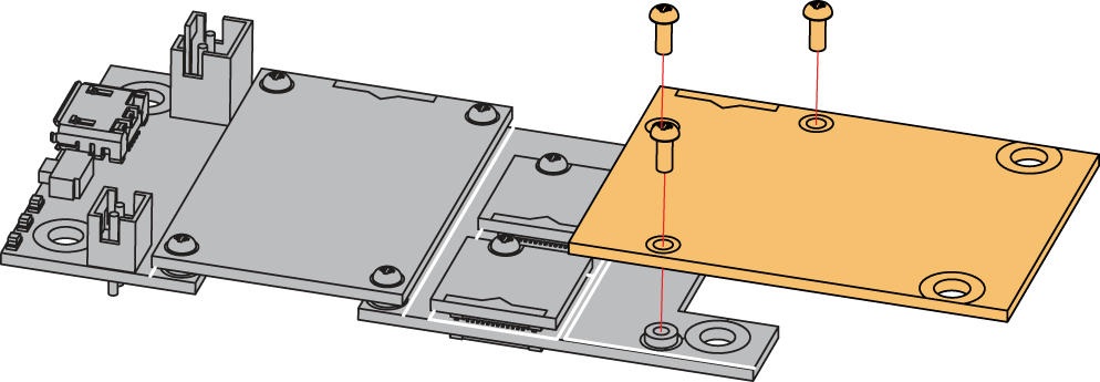 Figure 1: RAK14004 connection to WisBlock Base
Disassembling
The procedure in disassembling any type of WisBlock modules is the same.
- First, remove the screws.
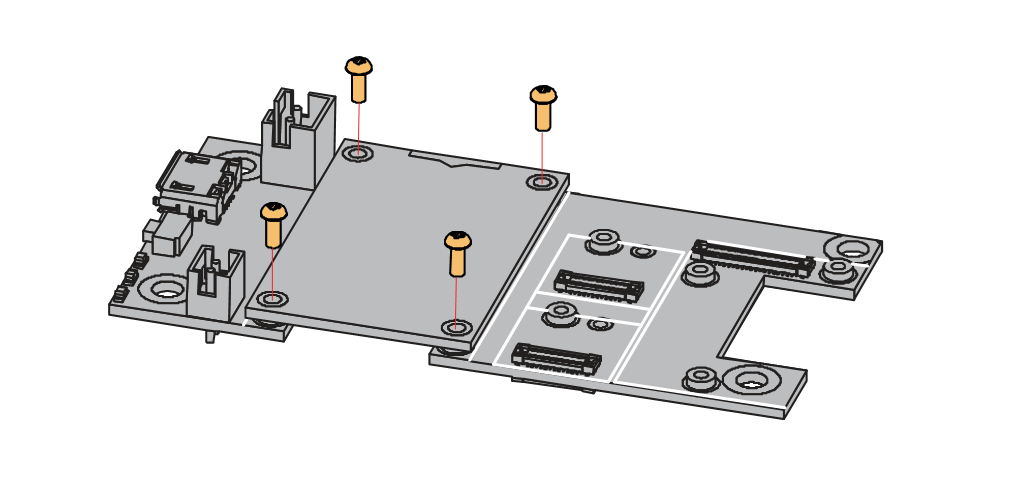 Figure 1: Removing screws from the WisBlock module
- Once the screws are removed, check the silkscreen of the module to find the correct location where force can be applied.
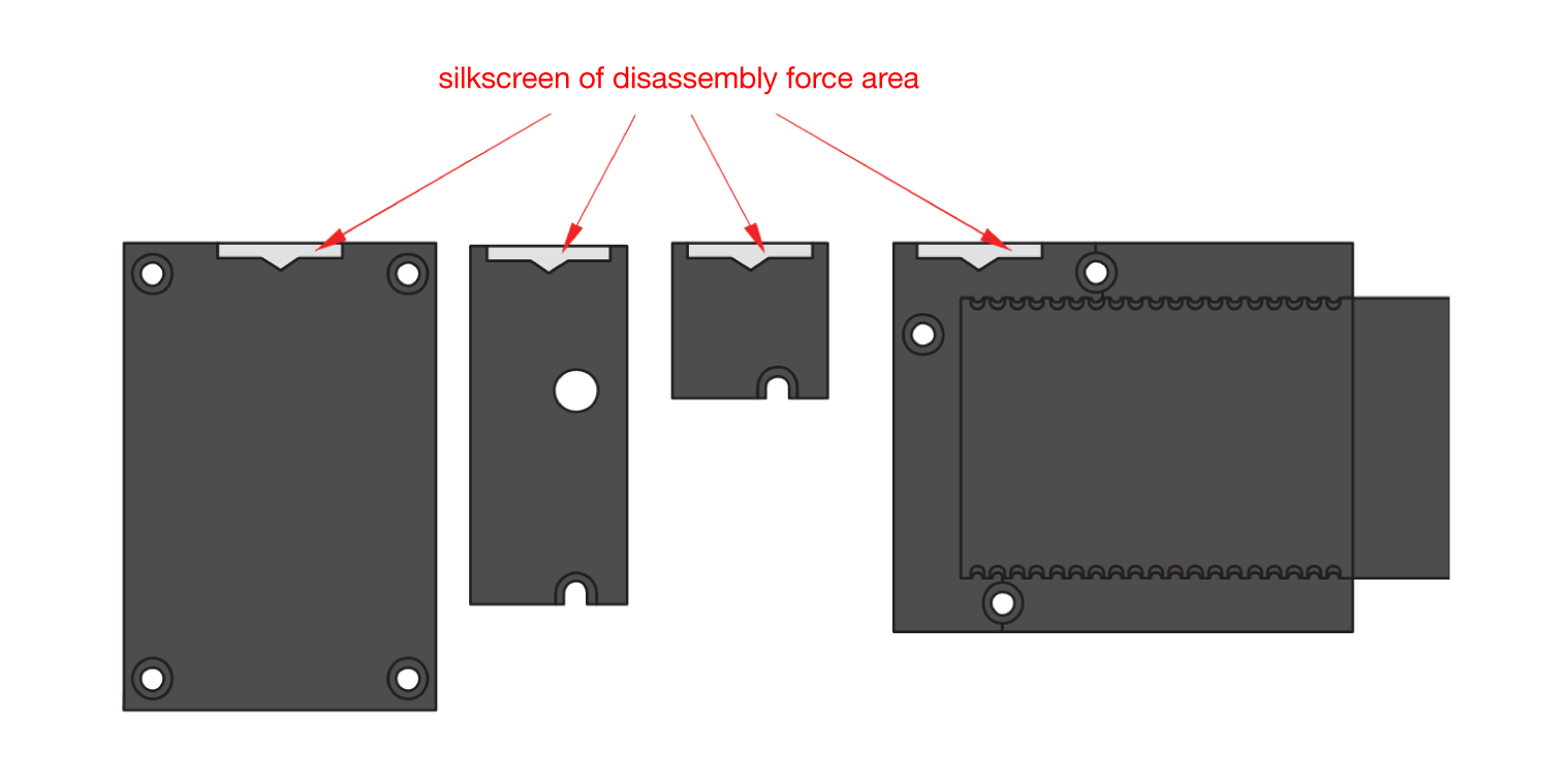 Figure 1: Detaching silkscreen on the WisBlock module
- Apply force to the module at the position of the connector, as shown in Figure 5, to detach the module from the baseboard.
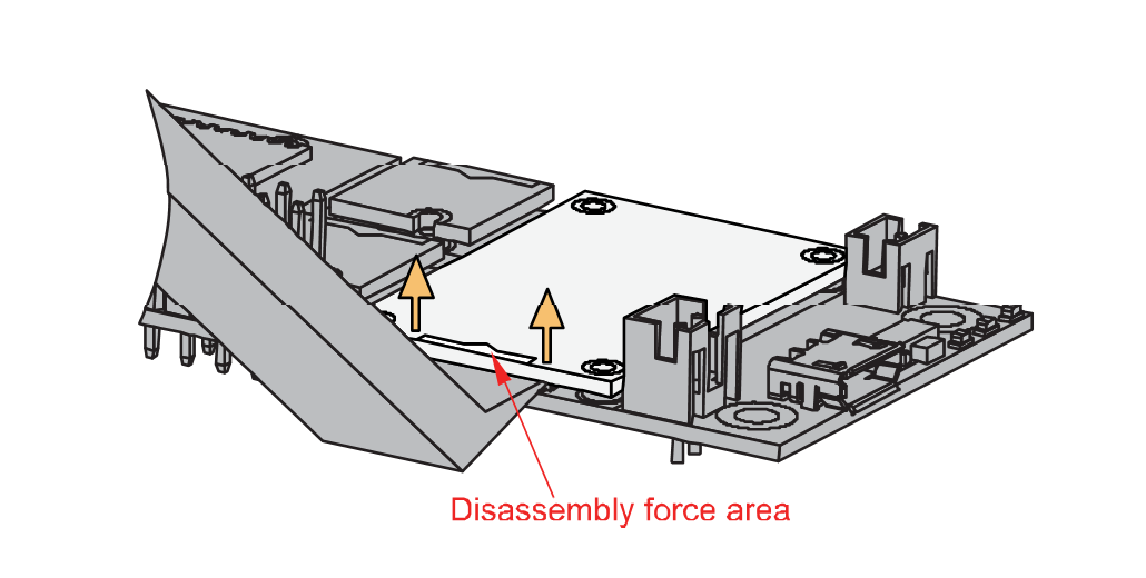 Figure 1: Applying even forces on the proper location of a WisBlock module
If you will connect other modules to the remaining WisBlock Base slots, check on the WisBlock Pin Mapper tool for possible conflicts.
After all this setup, you can now connect the battery (optional) and USB cable to start programming your WisBlock Core.
Software Configuration and Example
The RAK14004 module can be used in conjunction with RAK14009, RAK14010 or RAK14011 WisBlock Keypad modules. The quick links below go directly to the software guide for the specific WisBlock Keypad module you can use:
RAK14009 Keypad Example
- First, you need to select your WisBlock Core.
- Selecting the RAK4631 WisBlock Core:
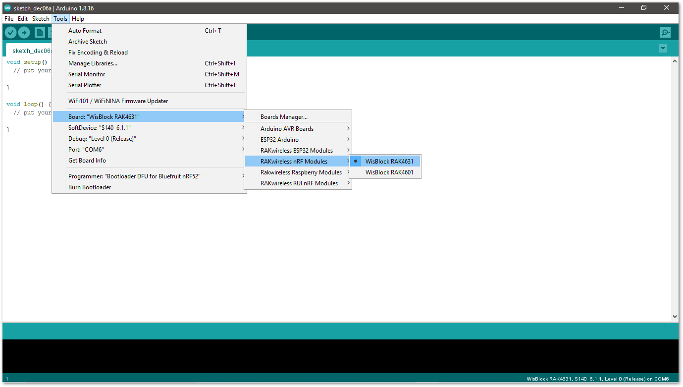 Figure 1: Selecting RAK4631 as WisBlock Core
- Selecting RAK11200 WisBlock Core Guide:
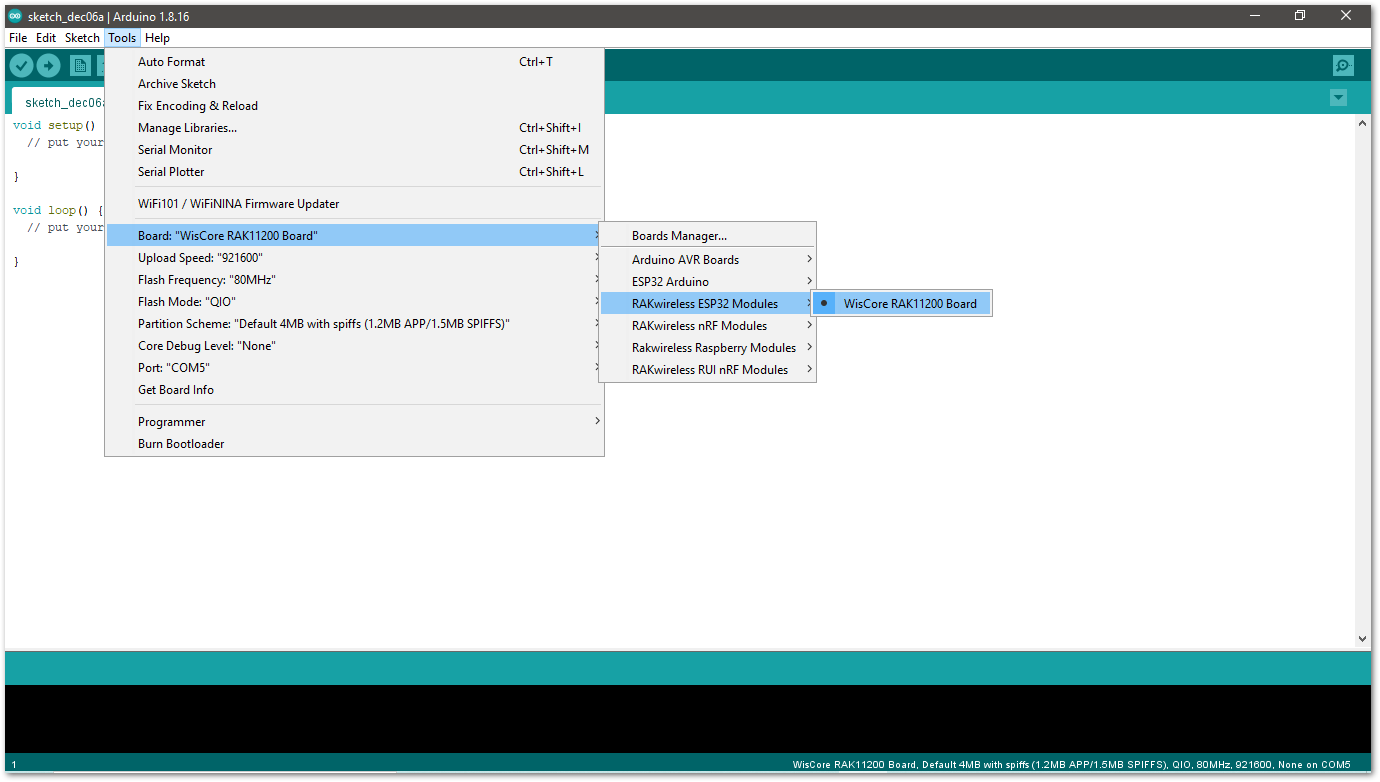 Figure 1: Selecting RAK11200 as WisBlock Core
- Selecting RAK11300 as WisBlock Core:
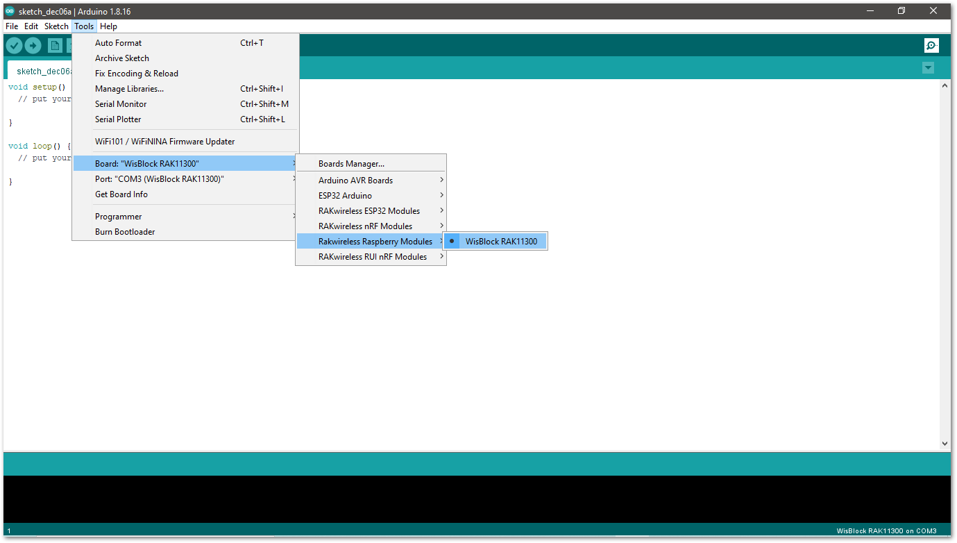 Figure 1: Selecting RAK11300 as WisBlock Core
- Copy the following example code into your Arduino IDE:
/**
   @file RAK14009_Keypad.ino
   @author rakwireless.com
   @brief 3*3 Keypad
   @version 0.1
   @date 2021-10-19
   @copyright Copyright (c) 2021
**/
#include <Wire.h>
#include "Arduino.h"
#define SLAVE_I2C_ADDRESS_DEFAULT            0x5F

// Sensor Register Addresses
#define SENSOR_GET_KEYPAD        0x01 // (r)   2 bytes
#define SENSOR_GET_I2C_ADDRESS   0x02  // (r)   1 bytes
#define SENSOR_SET_I2C_ADDRESS   0x03  // (w)   1 bytes
#define SENSOR_GET_VERSION       0x04 // (r)   1 bytes

#define KEYPAD_VERSION           0x02
#define KEYPAD_SIZE_X            0x03
#define KEYPAD_SIZE_Y            0x03
uint8_t InterruptFlag = 0;

void setup()
{
  //enable sensor
  pinMode(WB_IO2, OUTPUT);
  digitalWrite(WB_IO2, HIGH);
  delay(300);

  pinMode(WB_IO6, INPUT_PULLUP); //Interrupt
  pinMode(LED_BLUE, OUTPUT);
  digitalWrite(LED_BLUE, HIGH);
  attachInterrupt(WB_IO6, INTCallBack, RISING); // Enable interrupts.
  Wire.begin();
  Serial.begin(115200); // Initialize Serial for debug output.
  delay(3000);
  Serial.println("*******Keypad**********");
  uint8_t data = 0;
  read_from_Atmega328p(SENSOR_GET_VERSION, &data, 1);
  if (data != KEYPAD_VERSION)
  {
    Serial.println("sensor not find");
    while (1);
  }
  Serial.print("Sensor Firmware version: ");
  Serial.println(data);
  Serial.println();
  Serial.println("3*3 Keypad");
  delay(500);
}

void INTCallBack(void)
{
  InterruptFlag = 1;
}


/*brief: IIC Read data*/
uint8_t readflag = 0;
void read_from_Atmega328p(uint8_t reg, uint8_t *data, uint8_t length)
{
  Wire.beginTransmission(SLAVE_I2C_ADDRESS_DEFAULT);
  Wire.write(reg);
  Wire.endTransmission();    // stop transmitting
  delay(20);
  Wire.requestFrom(SLAVE_I2C_ADDRESS_DEFAULT, length);
  int i = 0;
  while ( Wire.available() ) // slave may send less than requested
  {
    data[i++] = Wire.read(); // receive a byte as a proper uint8_t
    readflag = 1;
  }
}

/*brief: IIC write data*/
void write_to_Atmega328p(uint8_t reg, uint8_t data)
{
  Wire.beginTransmission(SLAVE_I2C_ADDRESS_DEFAULT);
  Wire.write(reg);
  Wire.write(data);
  Wire.endTransmission();    // stop transmitting
}

void KeyPad_Print(void)
{
  if (InterruptFlag == 1)
  {
    uint8_t rDataBuf[8] = {0};
    uint8_t PrintDataBuf[2] = {0};
    uint8_t rDataFlag[2] = {0};
    read_from_Atmega328p(SENSOR_GET_KEYPAD, rDataBuf, KEYPAD_SIZE_X);
    if (readflag == 1)
    {
      Serial.println("-----------------------");
      for (uint8_t aCount = 0; aCount < KEYPAD_SIZE_X; aCount++)
      {
        for (uint8_t bCount = 0; bCount < KEYPAD_SIZE_Y; bCount++ )
        {
          uint8_t cmp = (rDataBuf[aCount] >> bCount) & 0x01;
          if (cmp == 0x01)
          {
            rDataFlag[0]++;
            if (rDataFlag[0] <= 2)
            {
              rDataFlag[1]++;
              PrintDataBuf[rDataFlag[0] - 1] = aCount * KEYPAD_SIZE_Y + bCount + 1;
            }
            else
            {
              rDataFlag[1] = 0;
              Serial.println("Error please do not press more than two buttons at the same time ");
              return;
            }
          }
        }
      }
      readflag = 0;
    }
    for (uint8_t pCount = 0; pCount < rDataFlag[1]; pCount++)
    {
      Serial.printf("K%d pressed\r\n", PrintDataBuf[pCount]);
    }
    Serial.println("-----------------------");
    Serial.println();
    InterruptFlag = 0;
  }
}

void loop() {
  KeyPad_Print();
  delay(100);
}
- Now, select the right Serial Port and upload the code.
- Selecting the RAK4631 Serial Port:
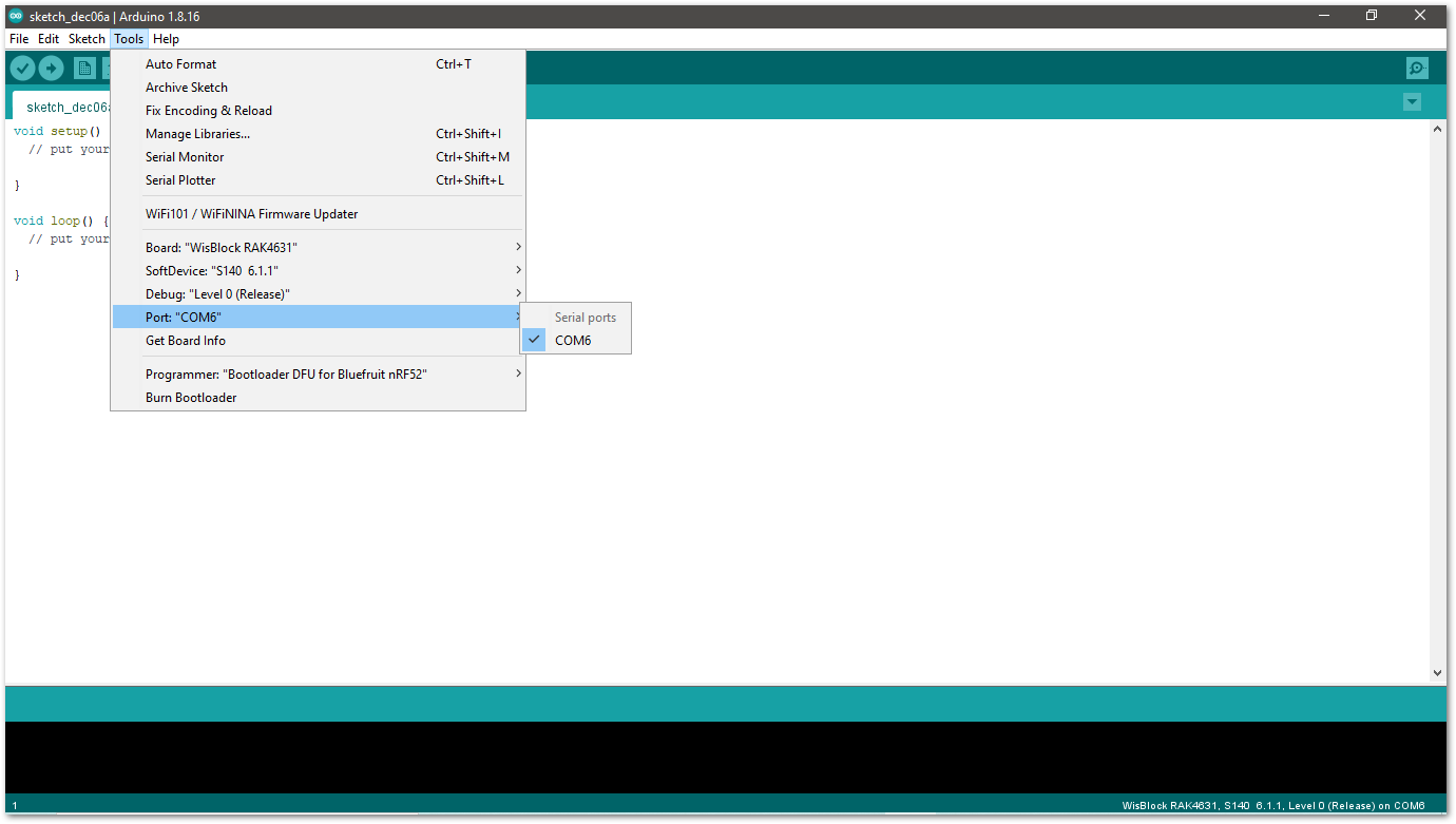 Figure 1: Selecting the RAK4631 Serial Port
- Selecting the RAK11200 Serial Port:
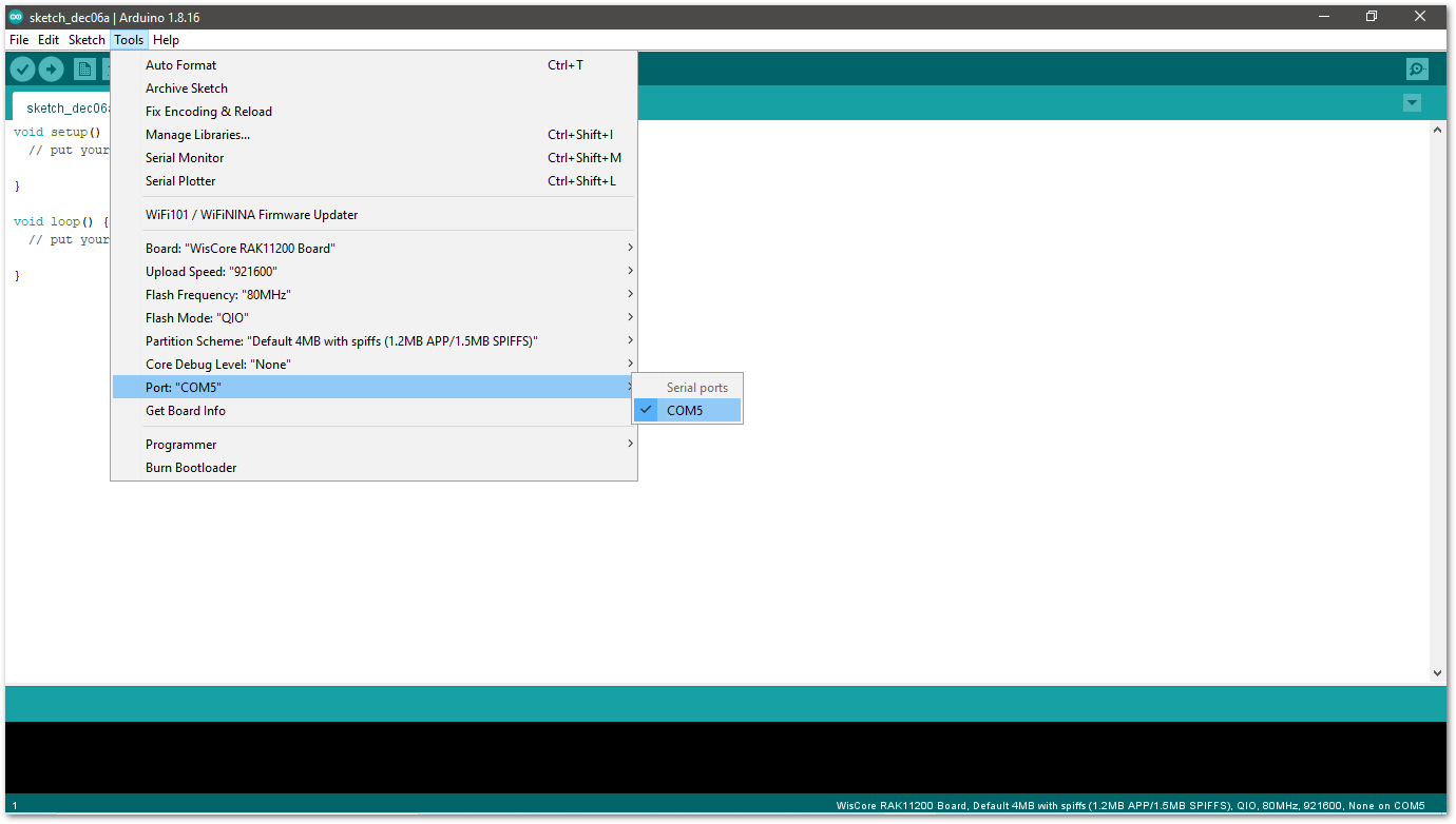 Figure 1: Selecting the RAK11200 Serial Port
- Before uploading your sketch, short circuit
BOOT0andGNDpin and press the reset button. Then click the Upload button using the configuration below.
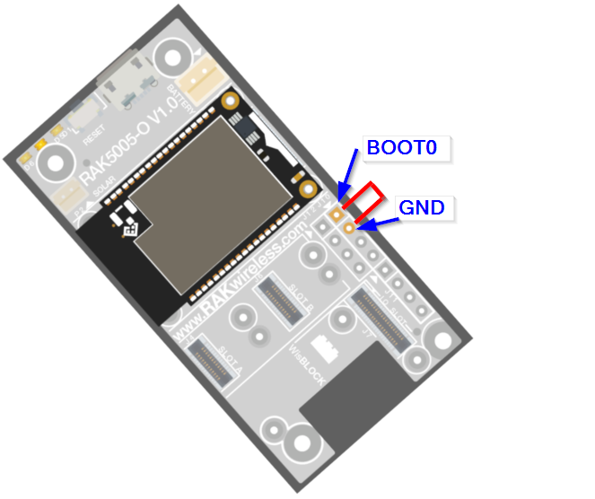 Figure 1: Force RAK11200 to download mode
- Selecting the RAK11300 Serial Port:
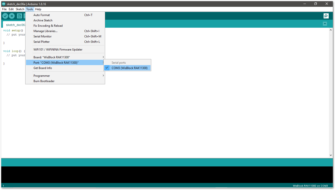 Figure 1: Selecting the RAK11300 Serial Port
- When you successfully uploaded the sample code, open the Serial Monitor of the Arduino IDE to check the module's reading logs. If you see the logs, as shown in Figure 10, then your RAK14004 module is properly communicating to the WisBlock Core using the I2C interface.
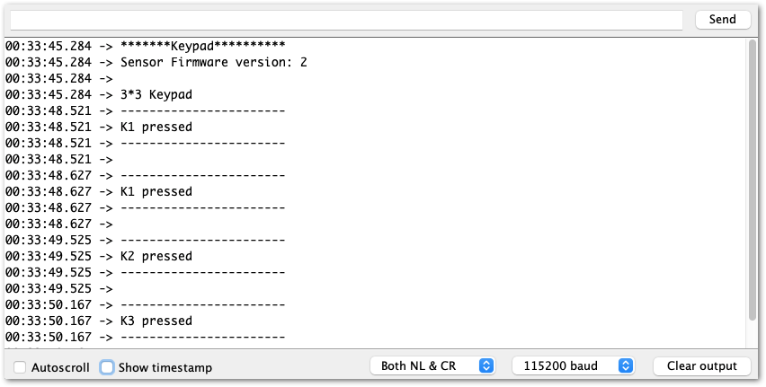 Figure 1: RAK14004 and RAK14009 on RAK4631 data logs
RAK14010 Keypad Example
- First, you need to select your WisBlock Core.
- Selecting RAK4631 as WisBlock Core:
 Figure 1: Selecting RAK4631 as WisBlock Core
- Selecting RAK11200 as WisBlock Core:
 Figure 1: Selecting RAK11200 as WisBlock Core
- Selecting RAK11300 as WisBlock Core:
 Figure 1: Selecting RAK11300 as WisBlock Core
- Copy the following example code into your Arduino IDE:
/**
   @file RAK14010_Keypad.ino
   @author rakwireless.com
   @brief 3*4 Keypad
   @version 0.1
   @date 2021-10-19
   @copyright Copyright (c) 2021
**/
#include <Wire.h>
#include "Arduino.h"
#define SLAVE_I2C_ADDRESS_DEFAULT            0x5F

//Sensor Register Addresses
#define SENSOR_GET_KEYPAD        0x01 // (r)   2 bytes
#define SENSOR_GET_I2C_ADDRESS   0x02  // (r)   1 bytes
#define SENSOR_SET_I2C_ADDRESS   0x03  // (w)   1 bytes
#define SENSOR_GET_VERSION       0x04 // (r)   1 bytes

#define KEYPAD_VERSION           0x02
#define KEYPAD_SIZE_X            0x03
#define KEYPAD_SIZE_Y            0x04
uint8_t InterruptFlag = 0;

void setup()
{
  //enable sensor
  pinMode(WB_IO2, OUTPUT);
  digitalWrite(WB_IO2, HIGH);
  delay(300);

  pinMode(WB_IO6, INPUT_PULLUP); //Interrupt
  pinMode(LED_BLUE, OUTPUT);
  digitalWrite(LED_BLUE, HIGH);
  attachInterrupt(WB_IO6, INTCallBack, RISING); // Enable interrupts.
  Wire.begin();
  Serial.begin(115200); // Initialize Serial for debug output.
  delay(3000);
  Serial.println("*******Keypad**********");
  uint8_t data = 0;
  read_from_Atmega328p(SENSOR_GET_VERSION, &data, 1);
  if (data != KEYPAD_VERSION)
  {
    Serial.println("sensor not find");
    while (1);
  }
  Serial.print("Sensor Firmware version: ");
  Serial.println(data);
  Serial.println();
  Serial.println("3*4 Keypad");
  delay(500);
}

void INTCallBack(void)
{
  InterruptFlag = 1;
}


/*brief: IIC Read data*/
uint8_t readflag = 0;
void read_from_Atmega328p(uint8_t reg, uint8_t *data, uint8_t length)
{
  Wire.beginTransmission(SLAVE_I2C_ADDRESS_DEFAULT);
  Wire.write(reg);
  Wire.endTransmission();    // stop transmitting
  delay(20);
  Wire.requestFrom(SLAVE_I2C_ADDRESS_DEFAULT, length);
  int i = 0;
  while ( Wire.available() ) // slave may send less than requested
  {
    data[i++] = Wire.read(); // receive a byte as a proper uint8_t
    readflag = 1;
  }
}

/*brief: IIC write data*/
void write_to_Atmega328p(uint8_t reg, uint8_t data)
{
  Wire.beginTransmission(SLAVE_I2C_ADDRESS_DEFAULT);
  Wire.write(reg);
  Wire.write(data);
  Wire.endTransmission();    // stop transmitting
}

void KeyPad_Print(void)
{
  if (InterruptFlag == 1)
  {
    uint8_t rDataBuf[8] = {0};
    uint8_t PrintDataBuf[2] = {0};
    uint8_t rDataFlag[2] = {0};
    read_from_Atmega328p(SENSOR_GET_KEYPAD, rDataBuf, KEYPAD_SIZE_X);
    if (readflag == 1)
    {
      Serial.println("-----------------------");
      for (uint8_t aCount = 0; aCount < KEYPAD_SIZE_X; aCount++)
      {
        for (uint8_t bCount = 0; bCount < KEYPAD_SIZE_Y; bCount++ )
        {
          uint8_t cmp = (rDataBuf[aCount] >> bCount) & 0x01;
          if (cmp == 0x01)
          {
            rDataFlag[0]++;
            if (rDataFlag[0] <= 2)
            {
              rDataFlag[1]++;
              PrintDataBuf[rDataFlag[0] - 1] = aCount * KEYPAD_SIZE_Y + bCount + 1;
            }
            else
            {
              rDataFlag[1] = 0;
              Serial.println("Error please do not press more than two buttons at the same time ");
              return;
            }
          }
        }
      }
      readflag = 0;
    }
    for (uint8_t pCount = 0; pCount < rDataFlag[1]; pCount++)
    {
      Serial.printf("K%d pressed\r\n", PrintDataBuf[pCount]);
    }
    Serial.println("-----------------------");
    Serial.println();
    InterruptFlag = 0;
  }
}

void loop() {
  KeyPad_Print();
  delay(100);
}
- Now select the right Serial Port and upload the code.
- Selecting the RAK4631 Serial Port:
 Figure 1: Selecting the RAK4631 Serial Port
- Selecting the RAK11200 Serial Port:
 Figure 1: Selecting the RAK11200 Serial Port
- Before uploading your sketch, short circuit
BOOT0andGNDpin and press the reset button. Then click the Upload button using the configuration below.
 Figure 1: Force RAK11200 to download mode
- Selecting the RAK11300 Serial Port:
 Figure 1: Selecting the RAK11300 Serial Port
When you successfully uploaded the sample code, open the Serial Monitor of the Arduino IDE to check the module's reading logs. If you see the logs, as shown in Figure 18, then your RAK14004 module is properly communicating to the WisBlock Core using the I2C interface.
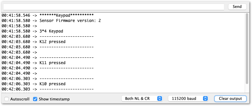 Figure 1: RAK14004 and RAK14010 on RAK4631 data logs
RAK14011 Keypad Example
- First, you need to select your WisBlock Core
- Selecting RAK4631 as WisBlock Core:
 Figure 1: Selecting RAK4631 as WisBlock Core
- Selecting RAK11200 as WisBlock Core:
 Figure 1: Selecting RAK11200 as WisBlock Core
- Before uploading your sketch, short circuit
BOOT0andGNDpin and press the reset button. Then click the Upload button using the configuration below.
 Figure 1: Force RAK11200 to download mode
- Selecting RAK11300 as WisBlock Core:
 Figure 1: Selecting RAK11300 as WisBlock Core
- Copy the following example code into your Arduino IDE:
/**
   @file RAK14011_Keypad.ino
   @author rakwireless.com
   @brief 4*4 Keypad
   @version 0.1
   @date 2021-10-19
   @copyright Copyright (c) 2021
**/
#include <Wire.h>
#include "Arduino.h"
#define SLAVE_I2C_ADDRESS_DEFAULT            0x5F

//Sensor Register Addresses
#define SENSOR_GET_KEYPAD        0x01 // (r)   2 bytes
#define SENSOR_GET_I2C_ADDRESS   0x02  // (r)   1 bytes
#define SENSOR_SET_I2C_ADDRESS   0x03  // (w)   1 bytes
#define SENSOR_GET_VERSION       0x04 // (r)   1 bytes

#define KEYPAD_VERSION           0x02
#define KEYPAD_SIZE_X            0x04
#define KEYPAD_SIZE_Y            0x04
uint8_t InterruptFlag = 0;

void setup()
{
  //enable sensor
  pinMode(WB_IO2, OUTPUT);
  digitalWrite(WB_IO2, LOW);
  delay(1000);
  digitalWrite(WB_IO2, HIGH);
  delay(300);

  pinMode(WB_IO6, INPUT_PULLUP); //Interrupt
  pinMode(LED_BLUE, OUTPUT);
  digitalWrite(LED_BLUE, HIGH);
  attachInterrupt(WB_IO6, INTCallBack, RISING); // Enable interrupts.
  Wire.begin();
  Serial.begin(115200); // Initialize Serial for debug output.
  delay(3000);
  Serial.println("*******Keypad**********");
  uint8_t data = 0;
  read_from_Atmega328p(SENSOR_GET_VERSION, &data, 1);
  if (data != KEYPAD_VERSION)
  {
    Serial.println("sensor not find");
    while (1);
  }
  Serial.print("Sensor Firmware version: ");
  Serial.println(data);
  Serial.println();
  Serial.println("4*4 Keypad");
  delay(500);
}

void INTCallBack(void)
{
  InterruptFlag = 1;
}


/*brief: IIC Read data*/
uint8_t readflag = 0;
void read_from_Atmega328p(uint8_t reg, uint8_t *data, uint8_t length)
{
  Wire.beginTransmission(SLAVE_I2C_ADDRESS_DEFAULT);
  Wire.write(reg);
  Wire.endTransmission();    // stop transmitting
  delay(20);
  Wire.requestFrom(SLAVE_I2C_ADDRESS_DEFAULT, length);
  int i = 0;
  while ( Wire.available() ) // slave may send less than requested
  {
    data[i++] = Wire.read(); // receive a byte as a proper uint8_t
    readflag = 1;
  }
}

/*brief: IIC write data*/
void write_to_Atmega328p(uint8_t reg, uint8_t data)
{
  Wire.beginTransmission(SLAVE_I2C_ADDRESS_DEFAULT);
  Wire.write(reg);
  Wire.write(data);
  Wire.endTransmission();    // stop transmitting
}

void KeyPad_Print(void)
{
  if (InterruptFlag == 1)
  {
    uint8_t rDataBuf[8] = {0};
    uint8_t PrintDataBuf[2] = {0};
    uint8_t rDataFlag[2] = {0};
    read_from_Atmega328p(SENSOR_GET_KEYPAD, rDataBuf, KEYPAD_SIZE_X);
    if (readflag == 1)
    {
      Serial.println("-----------------------");
      for (uint8_t aCount = 0; aCount < KEYPAD_SIZE_X; aCount++)
      {
        for (uint8_t bCount = 0; bCount < KEYPAD_SIZE_Y; bCount++ )
        {
          uint8_t cmp = (rDataBuf[aCount] >> bCount) & 0x01;
          if (cmp == 0x01)
          {
            rDataFlag[0]++;
            if (rDataFlag[0] <= 2)
            {
              rDataFlag[1]++;
              PrintDataBuf[rDataFlag[0] - 1] = aCount * KEYPAD_SIZE_Y + bCount + 1;
            }
            else
            {
              rDataFlag[1] = 0;
              Serial.println("Error please do not press more than two buttons at the same time ");
              return;
            }
          }
        }
      }
      readflag = 0;
    }
    for (uint8_t pCount = 0; pCount < rDataFlag[1]; pCount++)
    {
      Serial.printf("K%d pressed\r\n", PrintDataBuf[pCount]);
    }
    Serial.println("-----------------------");
    Serial.println();
    InterruptFlag = 0;
  }
}

void loop() {
  KeyPad_Print();
  delay(100);
}
- Now, select the right Serial Port and upload the code.
- Selecting the RAK4631 Serial Port:
 Figure 1: Selecting the RAK4631 Serial Port
- Selecting the RAK11200 Serial Port:
 Figure 1: Selecting the RAK11200 Serial Port
- Before uploading your sketch, short circuit
BOOT0andGNDpin and press the reset button. Then click the Upload button using the configuration below.
 Figure 1: Force RAK11200 to download mode
- Selecting the RAK11300 Serial Port
 Figure 1: Selecting the RAK11300 Serial Port
- When you successfully uploaded the sample code, open the Serial Monitor of the Arduino IDE to check the module's reading logs. If you see the logs, as shown in Figure 27, then your RAK14004 module is properly communicating to the WisBlock Core using the I2C interface.
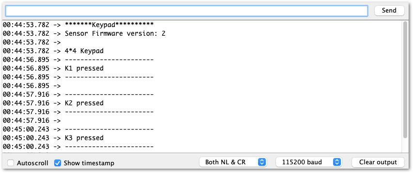 Figure 1: RAK14004 and RAK14011 on RAK4631 data logs