RAK15004 WisBlock FRAM Module Quick Start Guide
Prerequisite
What Do You Need?
Before going through each and every step on using the RAK15004 WisBlock module, make sure to prepare the necessary items listed below:
Hardware
- RAK15004 WisBlock FRAM module
- Your choice of WisBlock Base
- Your choice of WisBlock Core
- USB Cable
- Li-Ion/LiPo Battery (optional)
- Solar Charger (optional)
Software
- Download and install Arduino IDE.
- To add the RAKwireless Core boards on your Arduino Boards Manager, install the RAKwireless Arduino BSP.
Product Configuration
Hardware Setup
WisBlock can integrate this module which makes it easy for you to save big data on frequently accessed applications. To name a few of those applications are conversion tables, lookup tables or images, and even sound files. In addition, compared to the commonly used EEPROM modules, the RAK15004 FRAM memory module has superior write/erase cycles. This means that it mitigates the concern for rapid memory degradation.
For more information about RAK15004, refer to the Datasheet.
RAK15004 module can be connected to any slot of WisBlock Base to communicate with the WisBlock Core. It will work on SLOT A, C, D, E or F. Also, always secure the connection of the WisBlock module by using compatible screws.
Assembling and Disassembling of WisBlock Modules
Assembling
As shown in Figure 1, the location for sensor slots are properly marked by silkscreen. Follow carefully the procedure defined in WisBlock Base board assembly/disassembly instructions to attach a WisBlock module. Once attached, carefully fix the module with one or more pieces of M1.2 x 3 mm screws depending on the module.
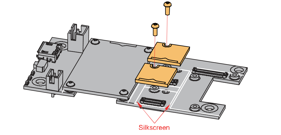 Figure 1: Sensor connection to WisBlock Base
Disassembling
The procedure in disassembling any type of WisBlock modules is the same.
- To begin disassembling, remove the screws.
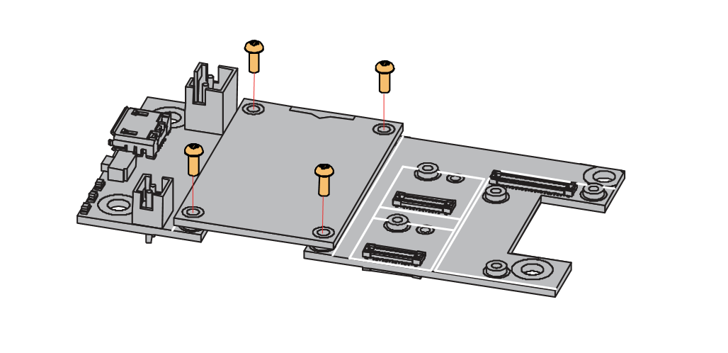 Figure 1: Removing screws from the WisBlock module
- After removing the screws, check the silkscreen of the module to find the correct location where force can be applied.
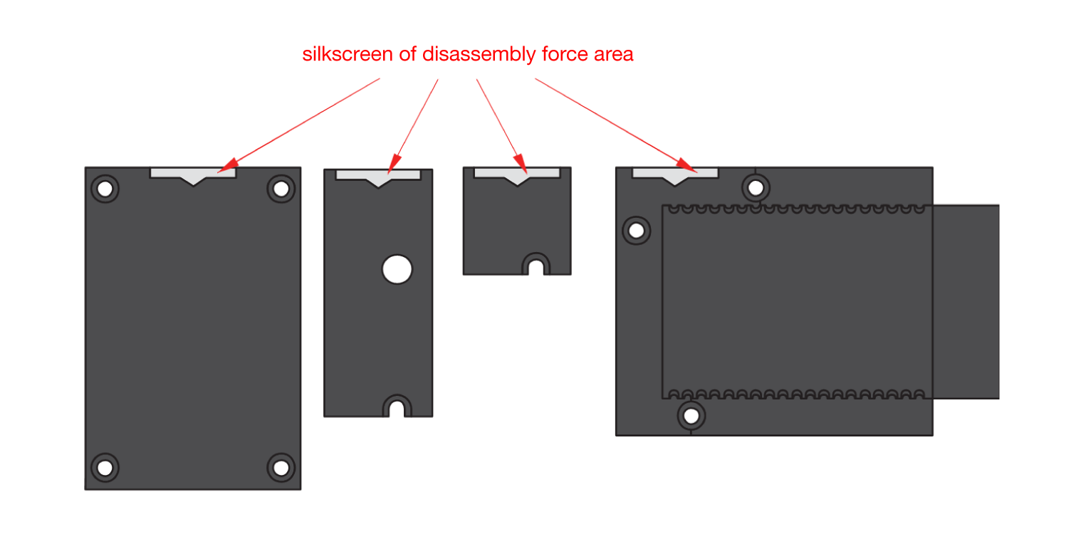 Figure 1: Detaching silkscreen on the WisBlock module
- Detach the module from the baseboard by applying force to the module at the position of the connector, as shown in Figure 4.
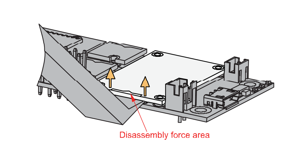 Figure 1: Applying even forces on the proper location of a WisBlock module
- If you will connect other modules to the remaining WisBlock Base slots, check on the WisBlock Pin Mapper. This tool finds possible pin conflicts.
- RAK15004 uses I2C communication lines with WP, which can cause possible conflict especially on some IO modules.
After all this setup, you can now connect the battery (optional) and USB cable to start programming your WisBlock Core.
Software Configuration and Example
Initial Test of the RAK15004 WisBlock Module
-
Install the RAKwireless Arduino BSP's for WisBlock by using the
https://raw.githubusercontent.com/RAKwireless/RAKwireless-Arduino-BSP-Index/main/package_rakwireless_index.jsonboard installation package. The WisBlock Core should now be available on the Arduino IDE. -
After that, you need to select the WisBlock Core you have, as shown in Figure 5 to Figure 7.
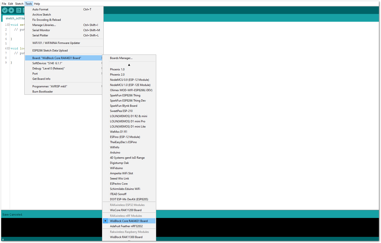 Figure 1: Selecting RAK4631 as WisBlock Core
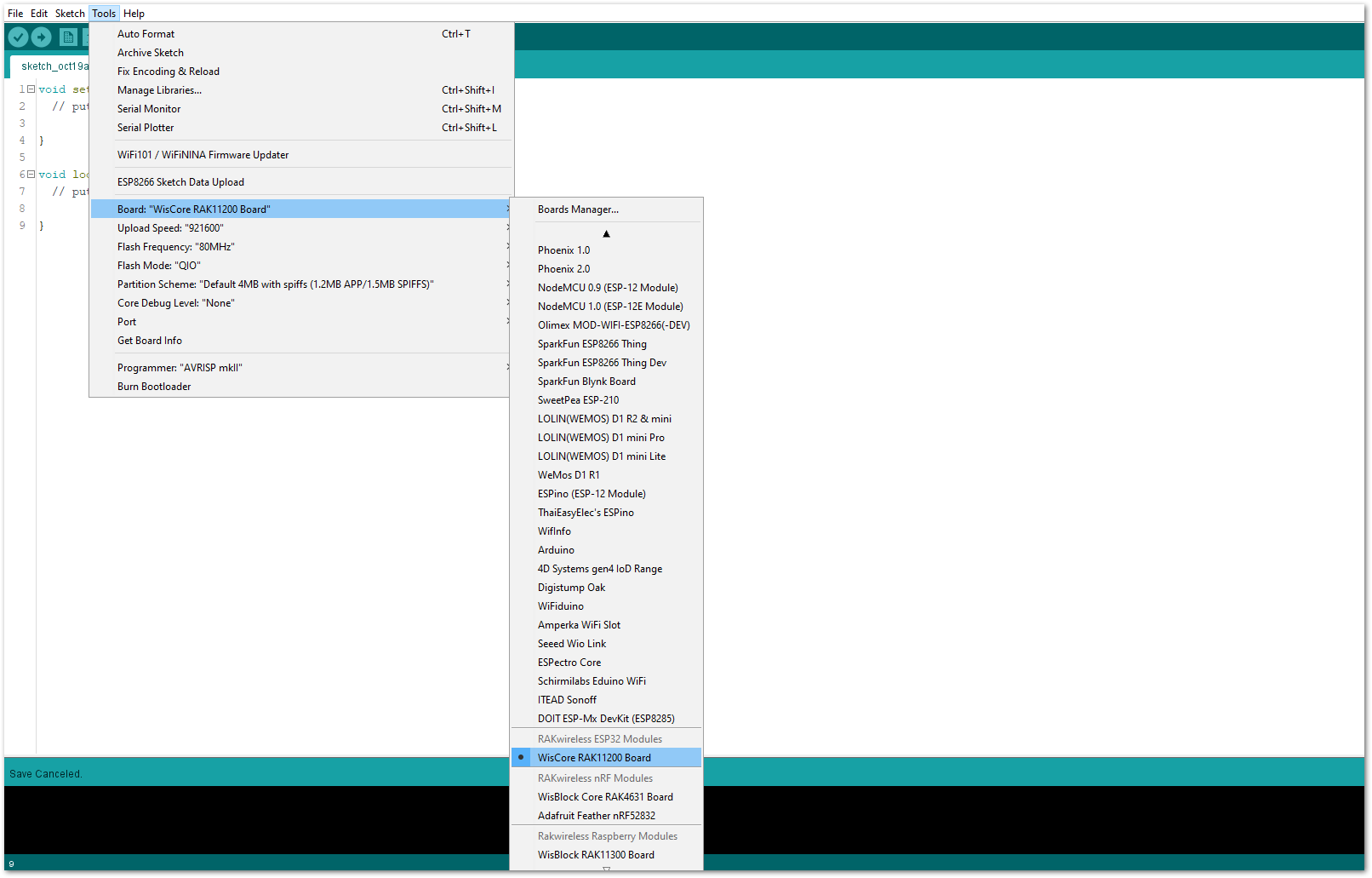 Figure 1: Selecting RAK11200 as WisBlock Core
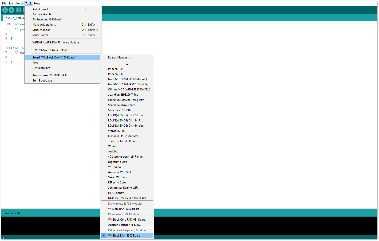 Figure 1: Selecting RAK11310 as WisBlock Core
- Next, copy the following sample code into your Arduino IDE.
Click to view the code
/**
   @file RAK1500x_FRAM_Read_Write_MB85RC.ino
   @author rakwireless.com
   @brief Test RAK1500x FRAM read and write functions.
					Suitable for RAK15003, RAK15004, RAK15005.
   @version 0.1
   @date 2021-4-13
   @copyright Copyright (c) 2022
**/
#include "RAK1500x_MB85RC.h"  // Click here to get the library: http://librarymanager/All#RAK1500x_MB85RC

#define DEV_ADDR    MB85RC_DEV_ADDRESS

/*
 * @note If installed in SlotB.
 *       Since IO2 is the power supply enable pin level is high.
 *       Only read operation can be performed on this slot.
 */
#define WP_PING   WB_IO1 // SlotA installation.
//#define WP_PING   WB_IO3 // SlotC installation.
//#define WP_PING   WB_IO5 // SlotD installation.

RAK_MB85RC MB85RC;

void setup()
{
  pinMode(WB_IO2, OUTPUT);
  digitalWrite(WB_IO2, HIGH);

  pinMode(WP_PING, OUTPUT);
  digitalWrite(WP_PING, LOW);

  time_t timeout = millis();
  Serial.begin(115200);
  while (!Serial)
  {
    if ((millis() - timeout) < 5000)
    {
      delay(100);
    }
    else
    {
      break;
    }
  }

	Wire.begin();
  while(MB85RC.begin(Wire , DEV_ADDR) == false)
  {
		Serial.println("MB85RC is not connected.");
    while(1)
    {
      delay(1000);
    }
  }

  switch (MB85RC.getDeviceType())
  {
    case MB85RC256:
      Serial.print("RAK15003(MB85RC256) ");
      break;
    case MB85RC512:
      Serial.print("RAK15004(MB85RC512) ");
      break;
    case MB85RC1:
      Serial.print("RAK15005(MB85RC1M) ");
      break;
    default:
      break;
  }
  Serial.println("initialized successfully.");
}

void loop()
{
  char writeDate[20]="Hello RAK1500X.";
  char readDate[20] = {0};
  Serial.println("Simple reading and writing test.");
  MB85RC.write(0x0000, (uint8_t*)writeDate , strlen(writeDate));
  MB85RC.read( 0x0000, (uint8_t*)readDate  , strlen(writeDate));
  Serial.println(readDate);

  Serial.println("Comparing whether the read and write content is consistent.");
  readWriteTest();

  Serial.println("Read the contents of the entire chip.");
  readEntireChip();

  Serial.println();
  Serial.println("Do nothing here, just love you!");
  while(1)
  {
    delay(100);
  }
}

/*
 * @brief Comparing whether the read and write content is consistent.
 *        Can be used to test the probability of FRAM read and write errors.
 */
void readWriteTest()
{
  char writeBuf[16] = ">>Test RAK1500X";
  char readBuf[16] = {0};
  uint32_t successCount = 0;
  uint32_t failCount = 0;
  uint32_t productSize = MB85RC.getDeviceCapacity();
  float progress = 0;
  time_t interval = millis();

  for(uint32_t i = 0; i < productSize; i+=sizeof(writeBuf))
  {
    MB85RC.write(i, (uint8_t*)writeBuf , sizeof(writeBuf));
    MB85RC.read( i, (uint8_t*)readBuf  , sizeof(readBuf));
    if(memcmp(writeBuf , readBuf , sizeof(readBuf)) == 0)
    {
      successCount++;
    }
    else
    {
      failCount++;
    }
    if((millis() - interval) > 1000)
    {
      interval = millis();
      Serial.printf("Test progress: %5.2f%% , successCount: %ld , failCount:%ld \n",progress,successCount,failCount);
    }
    progress = (float)(i+sizeof(writeBuf)) * 100 / productSize;
    memset(readBuf , '0' , sizeof(readBuf));
    delay(1);
  }
  Serial.printf("Test progress: %5.2f%% , successCount: %ld , failCount:%ld \n",progress,successCount,failCount);
}

/*
 * @brief Read the contents of the entire chip.
 */
void readEntireChip()
{
  char readBuf[32] = {0};
  uint32_t productSize = MB85RC.getDeviceCapacity();
  Serial.println();
  for(uint32_t i = 0; i < productSize; i+=sizeof(readBuf))
  {
    MB85RC.read( i, (uint8_t*)readBuf  , sizeof(readBuf));
    Serial.print("0x");
    Serial.print(i,HEX);
    Serial.print("\t");
    for(uint32_t j = 0; j < sizeof(readBuf); j++)
    {
      Serial.print("0x");
      Serial.print(readBuf[j],HEX);
      Serial.print(' ');
    }
    Serial.println();
  }
}
If you experience any error in compiling the example sketch, check the updated code for your WisBlock Core Module. You can find it on the RAK15004 WisBlock Example Code Repository. The sample code on GitHub will work on all WisBlock Core.
- Once the example code is open, install the RAK1500x_MB85RC library. Click the highlighted link, as shown in Figure 8 and Figure 9.
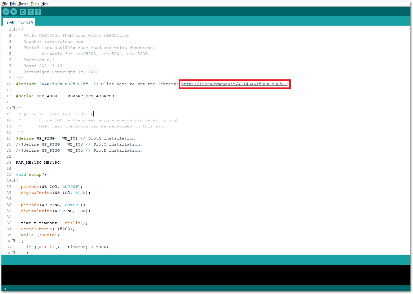 Figure 1: Accessing the library used for RAK15004 Module
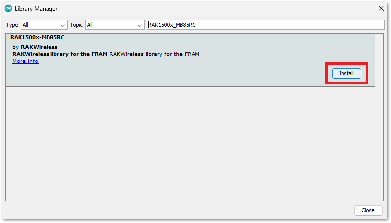 Figure 1: Installing the compatible library for RAK15004 Module
- After a successful library installation, select the right serial port and upload the code, as shown in Figure 10 and Figure 11.
If you're using the RAK11200 as your WisBlock Core, the RAK11200 requires the Boot0 pin to be configured properly first before uploading. If not done properly, uploading the source code to RAK11200 will fail. Check the full details on the RAK11200 Quick Start Guide.
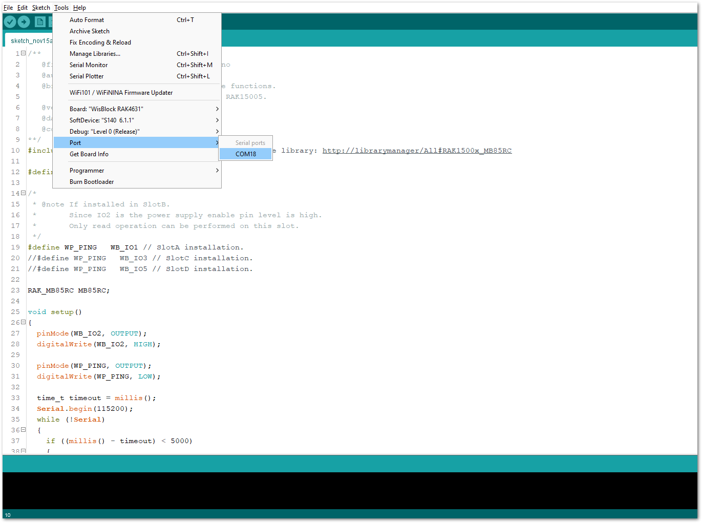 Figure 1: Selecting the correct Serial Port
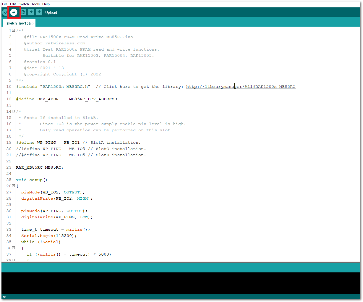 Figure 1: Uploading the RAK15004 example code
- When you have successfully uploaded the example sketch, you'll see that the WisBlock Core will perform a Write-Read test on the FRAM. Then, it reads out all its contents.
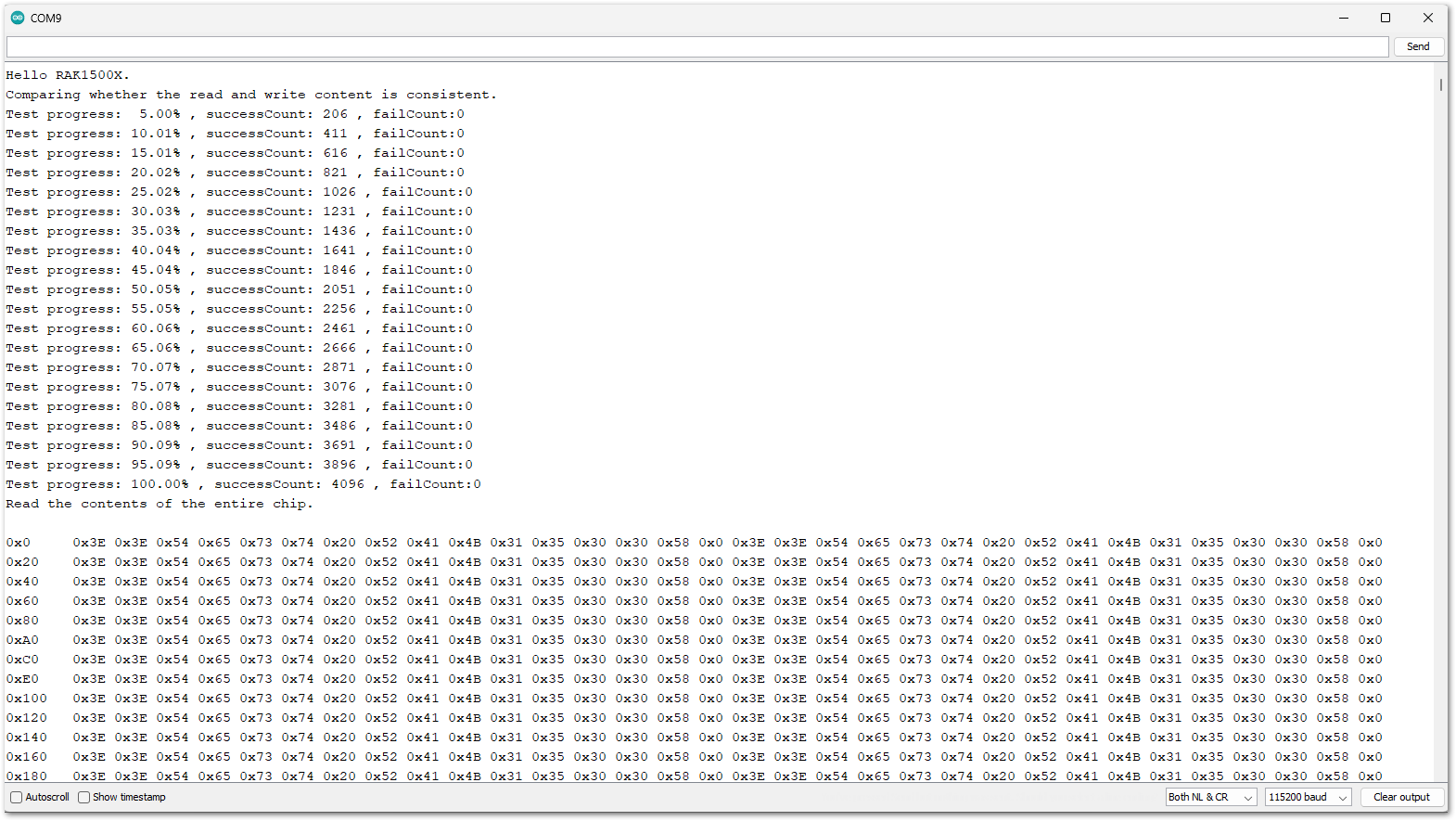 Figure 1: Uploading the RAK15004 example code