RAK5811 WisBlock 0-5V Interface Module Quick Start Guide
Prerequisite
What Do You Need?
Before going through each and every step on using the RAK5811 WisBlock module, make sure to prepare the necessary items listed below:
Hardware
- RAK5811 WisBlock 0-5V Interface Module
- WisBlock Base
- Your choice of WisBlock Core
- USB Cable
- Li-Ion/LiPo battery (optional)
- Solar charger (optional)
Software
Arduino
- Download and install Arduino IDE.
- To add the RAKwireless Core boards on your Arduino Boards Manager, install the RAKwireless Arduino BSP.
PlatformIO
To use the WisBlock Core modules with PlatformIO, you need to install a small script named RAK_PATCH. The script can be installed on WisBlock Core RAK4631, RAK11200, and RAK11310. Install RAK_PATCH on PlatformIO.
RAK_PATCH script was tested only on Windows 10 and Ubuntu. In the case of the Raspberry PI 2040 platform update on PlatformIO, the RAK_PATH script must be executed again after the platform update.
Product Configuration
Overview
To give you a better understanding of how the RAK5811 Module works, the block diagram is provided in this section.
Block Diagram
In the RAK5811 module, as shown in Figure 1, the 0-5 V input signal is connected to the operational amplifier by the R1/R2 voltage divider. The operational amplifier output is routed to an analog input of the MCU to be digitalized by an internal ADC.
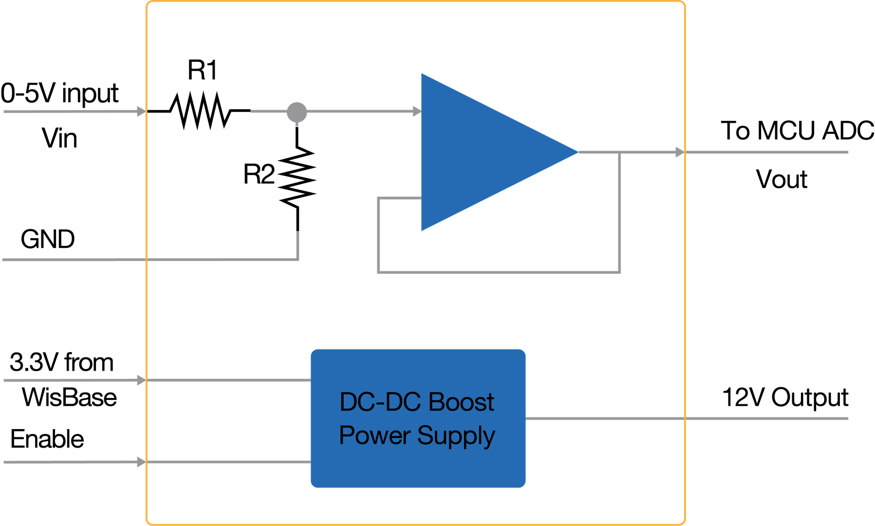 Figure 1: RAK5811 Block Diagram
Once the signal is digitalized, you can recover the original voltage value by applying the following relation:
 Figure 1: RAK5811 Voltage divider relation
Where Vout is the WisBlock Core read voltage, Vin is the analog input voltage (0-5 V). From the voltage divider R1 is 1 MΩ and R2 is 1.5 MΩ, so the final relationship is: Vin = Vout / 0.6.
As shown in Figure 1, the module provides an output of 12 V to power industrial sensors. This 12 V output is controlled by a TPS60146 DC-DC booster. The Enable pin allows to control the output voltage of the booster module and sets the RAK5811 module into a low power consumption mode.
Hardware Setup
Installation
Mounting Mechanism
The RAK5811 module is part of the WisBlock Interface category, which connects to the baseboard through the IO slot. Execute the following instructions carefully to install your WisConnector into the Baseboard:
- Keep the RAK5811 module parallel to the baseboard, and gently place and plug WisConnector into the IO slot receptacle of the baseboard. The IO slot has an outer silkscreen on it to assist with the alignment. At this point, apply force evenly along with the module and press again. There will be a sound to confirm the successful completion of the attachment process.
For detailed instructions, refer to the WisBlock Installation Guide.
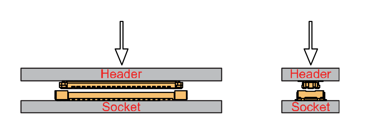 Figure 1: WisConnector and IO slot
- Always secure the RAK5811 module with 3 x M1.2 x3 pan head screws, as shown in Figure 4 below.
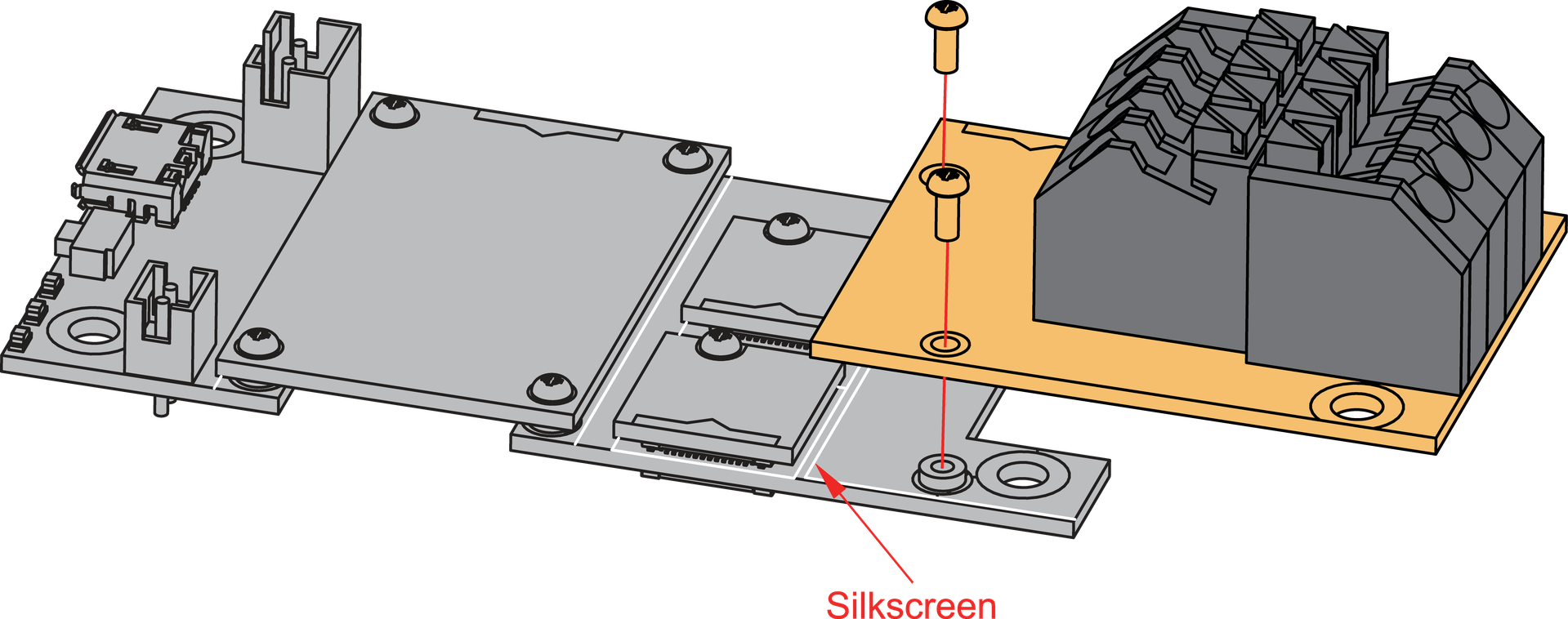 Figure 1: RAK5811 mounting mechanism on a WisBlock Base module
RAK5811 Fast Crimping Terminal Mechanism
The RAK5811 features a fast-crimping terminal connector to simplify and ensure the wiring process on the fields. The fast-crimping terminal can support cable with a width between 20 AWG to 24 AWG. The usual stripping length is around 6 to 7 mm.
As shown in Figure 5, during the crimping process, you should first press down and maintain the spring head of the crimping terminal firmly, then insert the stripped cable head into the corresponding connector’s hole. Once inserted correctly, release the spring head, and the crimping process is completed.
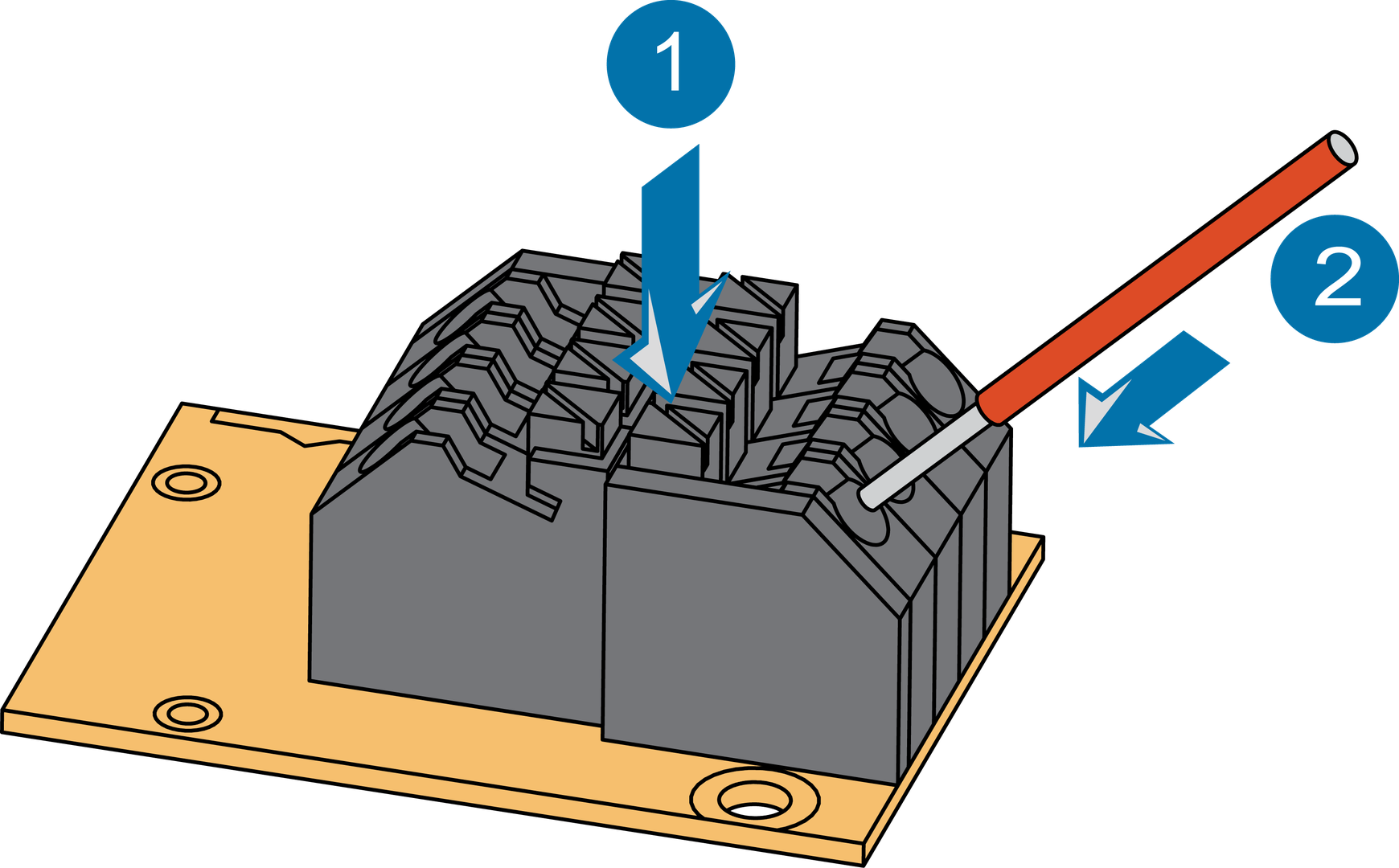 Figure 1: RAK5811 Crimping
To learn more about the Pinout Diagram of the RAK5811 Module, refer to the Datasheet.
Disassembling Procedure
The procedure in disassembling any type of WisBlock module is the same.
- Remove the screws.
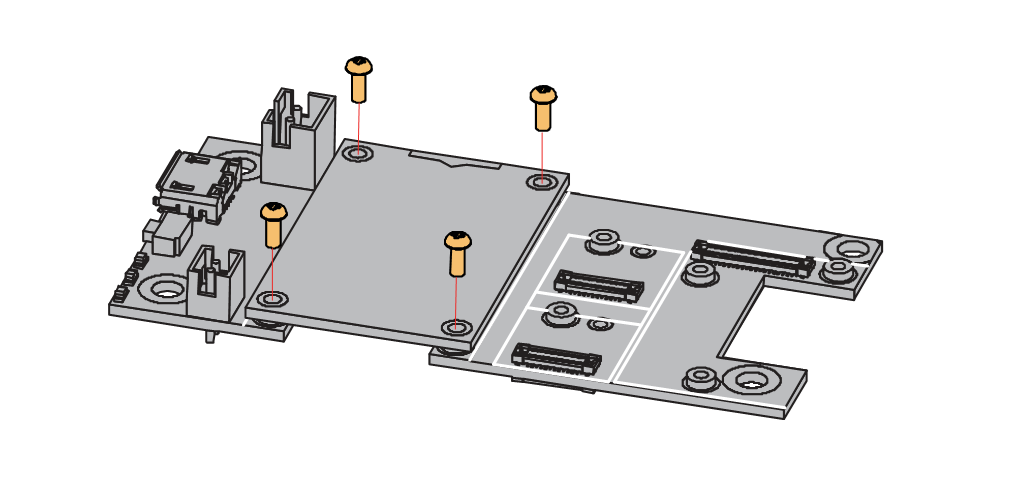 Figure 1: Removing screws from the WisBlock module
- Once the screws are removed, check the silkscreen of the module to find the correct location where force can be applied.
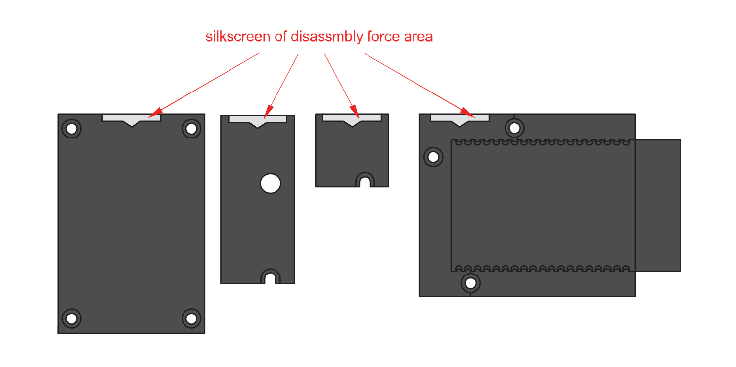 Figure 1: Detaching silkscreen on the WisBlock module
- Apply force to the module at the position of the connector, as shown in Figure 8, to detach the module from the baseboard.
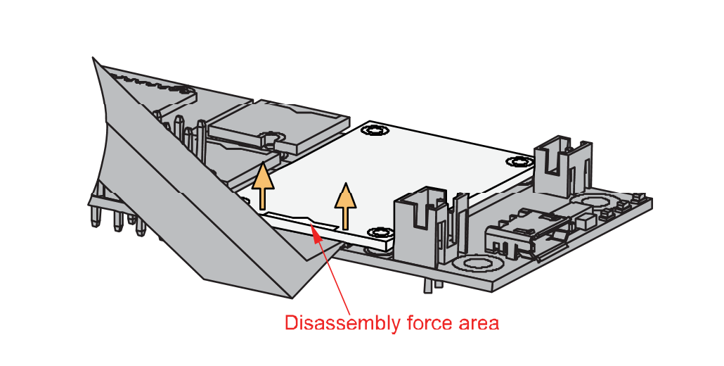 Figure 1: Applying even forces on the proper location of a WisBlock module
If you will connect other modules to the remaining WisBlock Base slots, check on the WisBlock Pin Mapper tool for possible conflicts.
- Battery can cause harm if not handled properly.
- Only 3.7-4.2 V Rechargeable LiPo batteries are supported. It is highly recommended not to use other types of batteries with the system unless you know what you are doing.
- If a non-rechargeable battery is used, it has to be unplugged first before connecting the USB cable to the USB port of the board to configure the device. Not doing so might damage the battery or cause fire.
- Make sure the battery wires match the polarity on the RAK WisBlock Base Board. Not all batteries have the same wiring.
- Only 5 V solar panels are supported. Do not use 12 V solar panels. It will destroy the charging unit and eventually other electronic parts.
Software Configuration and Example
Arduino Setup
The RAK5811 module includes a 12 V voltage source which is controlled by the WisBlock Core module via the Enable pin of the WisBlock Base. This GPIO must be set to HIGH before sampling. The 12 V voltage source is also designed to provide the power supply to the operational amplifier of the module. Before connecting a sensor to the RAK5811 module, you must be sure that the sensor can safely operate at 5 V.
If you already installed the RAKwireless Arduino BSP, the WisBlock Core and example code should now be available on the Arduino IDE.
- Select the WisBlock Core you have, as shown in Figure 9 to Figure 11.
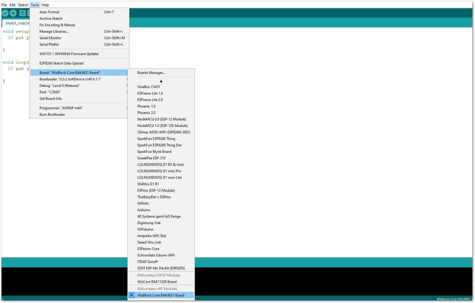 Figure 1: Selecting RAK4631 as WisBlock Core
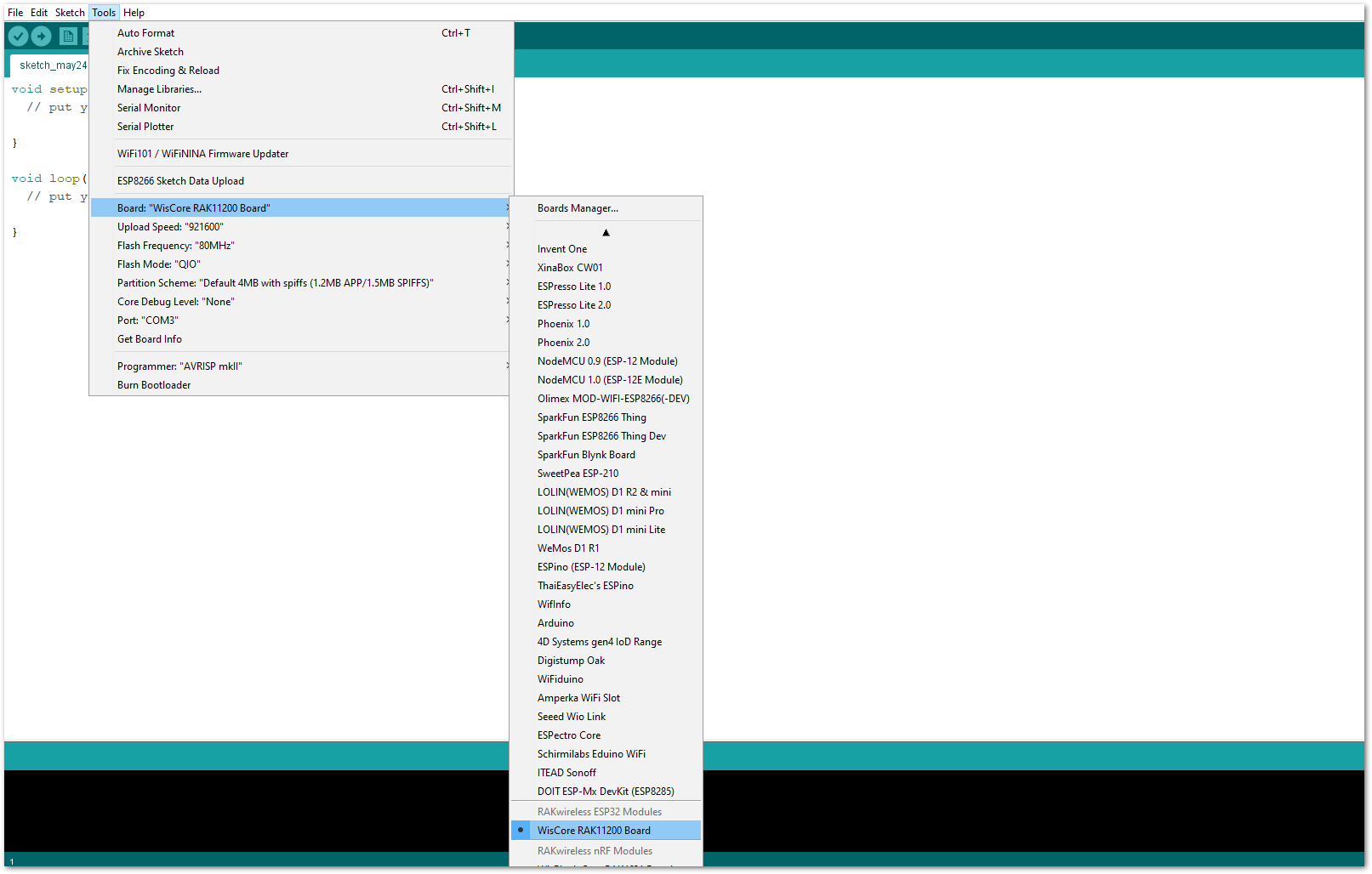 Figure 1: Selecting RAK11200 as WisBlock Core
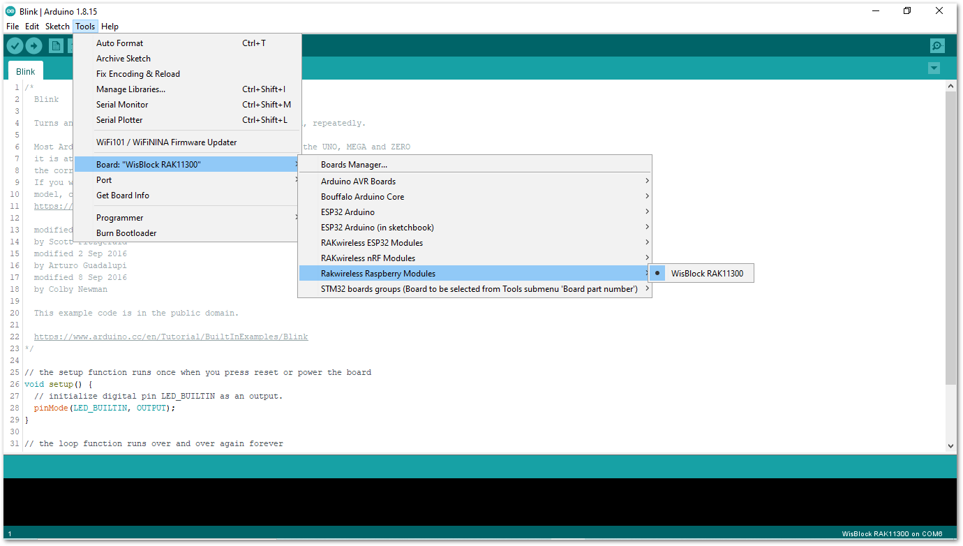 Figure 1: Selecting RAK11310 as WisBlock Core
- You can access the programming guide for the RAK5811 module by opening the example codes depending on your WisBlock Core, as shown in Figure 12 to Figure 14.
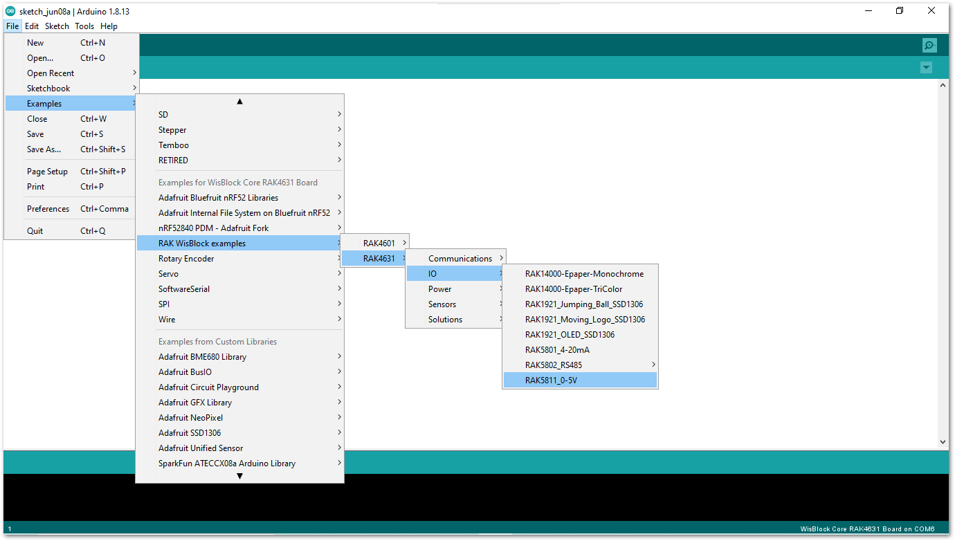 Figure 1: Opening RAK5811 example for RAK4631 WisBlock Core
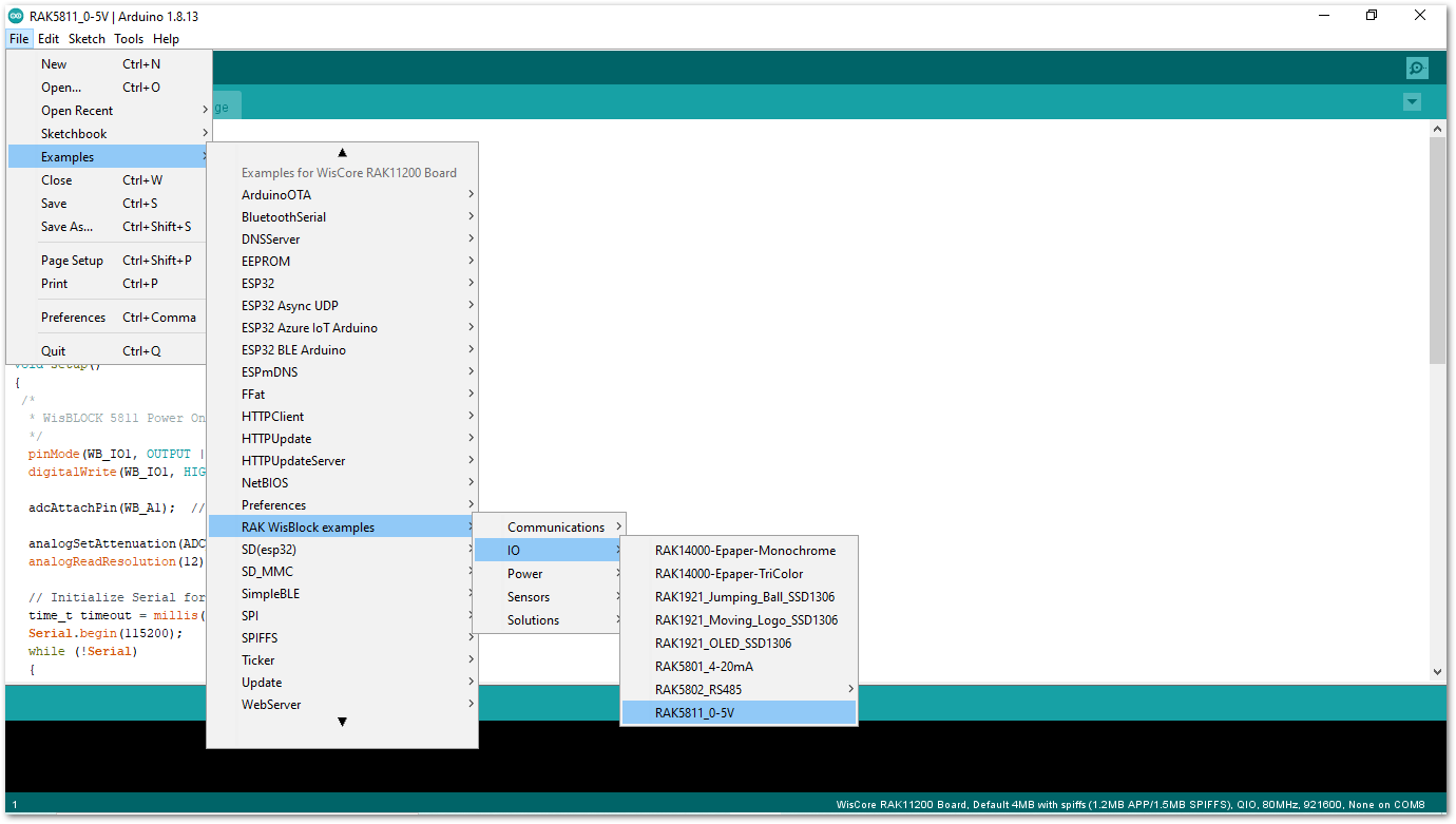 Figure 1: Opening RAK5811 example for RAK11200 WisBlock Core
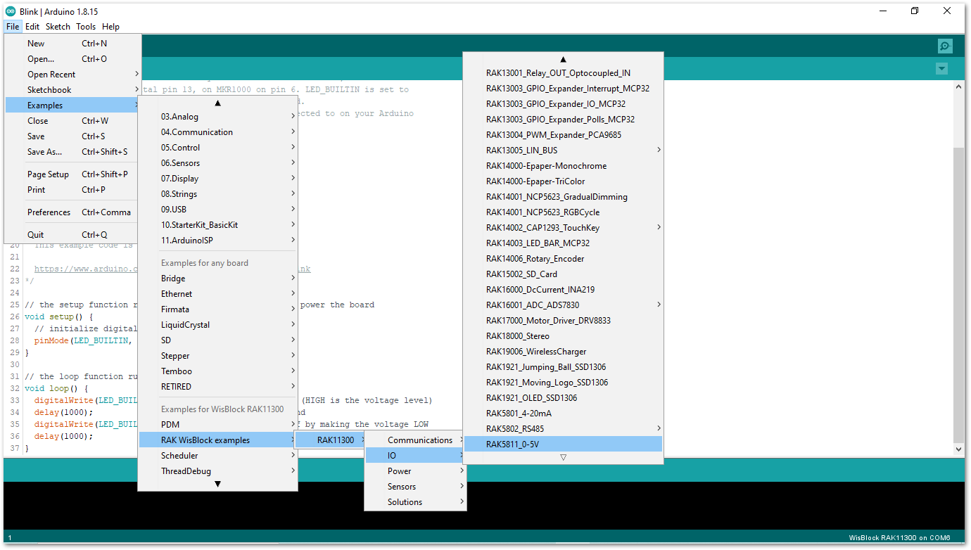 Figure 1: Opening RAK5811 example for RAK11310 WisBlock Core
- After opening the example code, you can now select the right port and upload the code, as shown in Figure 15 and Figure 16.
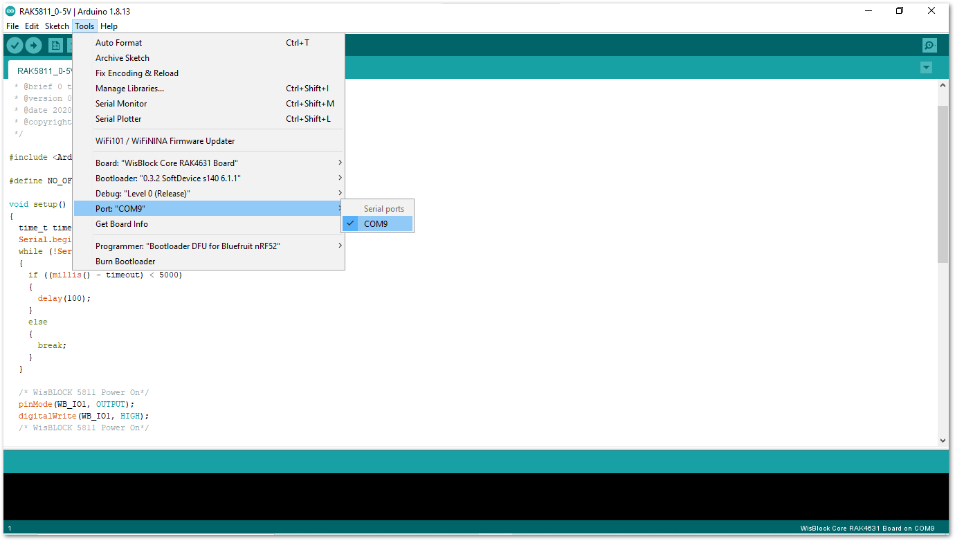 Figure 1: Selecting the correct Serial Port
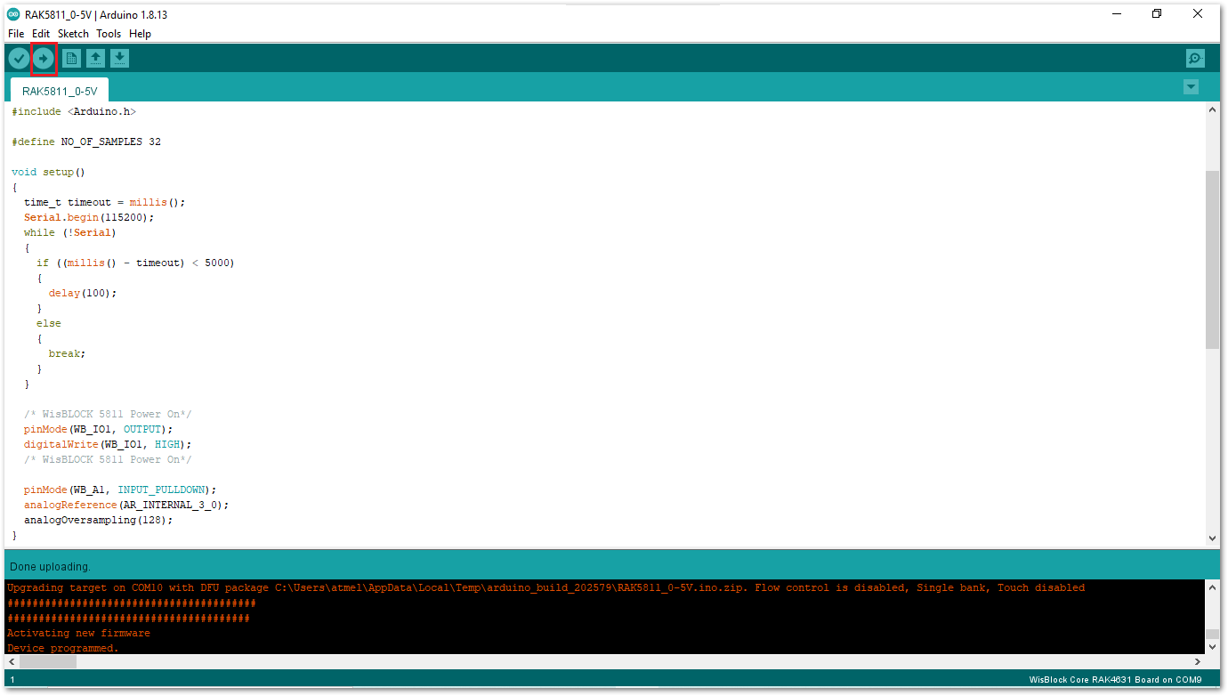 Figure 1: Uploading the RAK5811 example code
- When you successfully uploaded the example sketch, open the Serial Monitor of the Arduino IDE to see the ADC reading logs, as shown in Figure 17 and Figure 18.
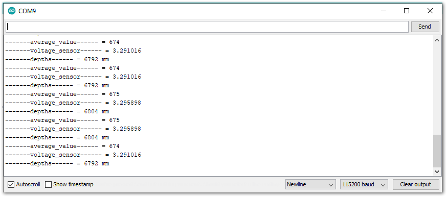 Figure 1: RAK4631 and RAK5811 example log
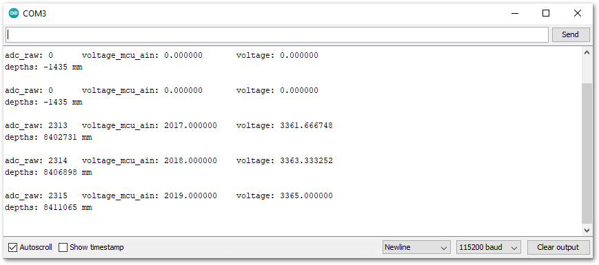 Figure 1: RAK11200 and RAK5811 example log
PlatformIO Setup (Optional)
To develop using PlatformIO, you need to install the RAK_PATCH script as described in the section PlatformIO.
-
Open the RAK5811 Arduino example. Then install the libraries, build the project, and save the sketch.
-
Now launch open Platformio > PIO Home and click on import Arduino project button, as shown in Figure 19.
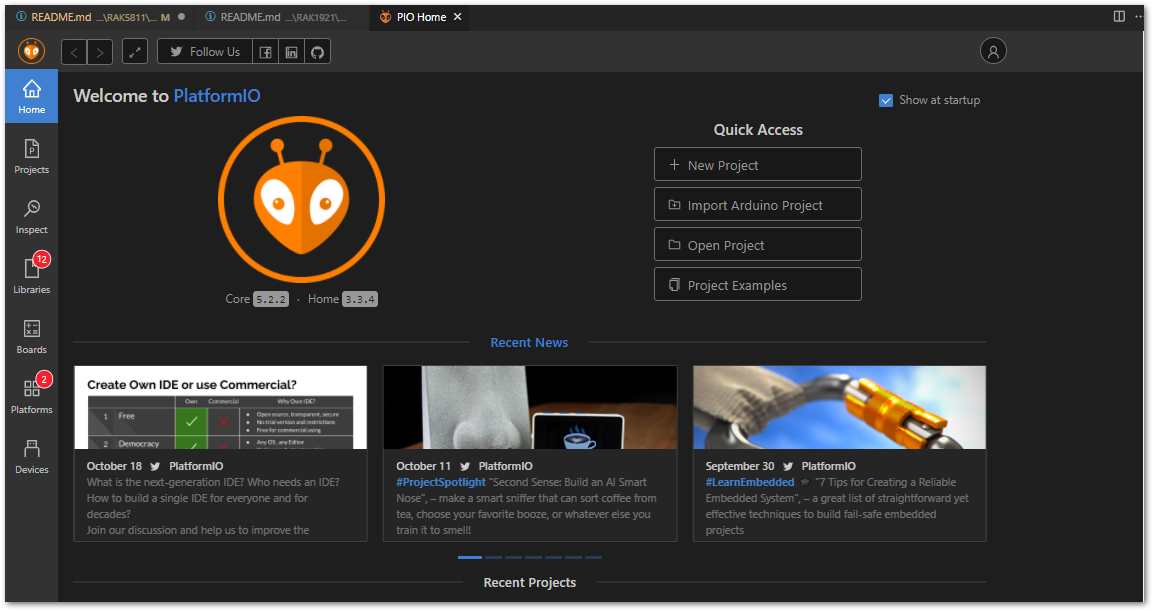 Figure 1: Import Arduino project
- Configure Import Arduino Project parameters:
- On the boards list, select your favorite WisCore. For example: WisCore RAK11310 Board (RAKwireless) (Label 1).
- Check Use libraries installed by Arduino IDE (Label 2).
- Choose the directory of your Arduino project to be imported (Label 3).
- To finish import, click on the Import button (Label 4).
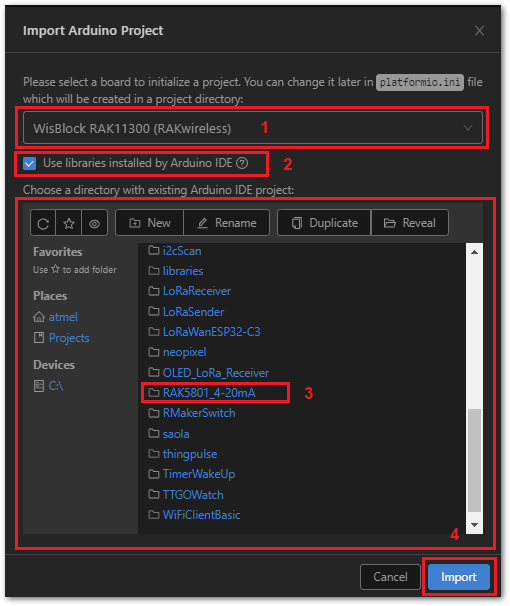 Figure 1: Configure Import parameters
- On the Trust author window, click Yes.
 Figure 1: Trust author window
Now, your project is imported successfully.
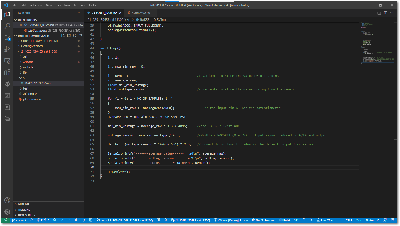 Figure 1: Imported Arduino project
On the imported project, check the platformio.ini file:
The parameter libs_extra_dirs is your Arduino library directory. In case of upload error, add the parameter upload_port.
[env:rak11300]
platform = raspberrypi
board = rak11300
framework = arduino
lib_extra_dirs = ~/Documents/Arduino/libraries
upload_port = COM8
If your project is running on Windows, use the Device Manager program to find correct the COM port allocated.
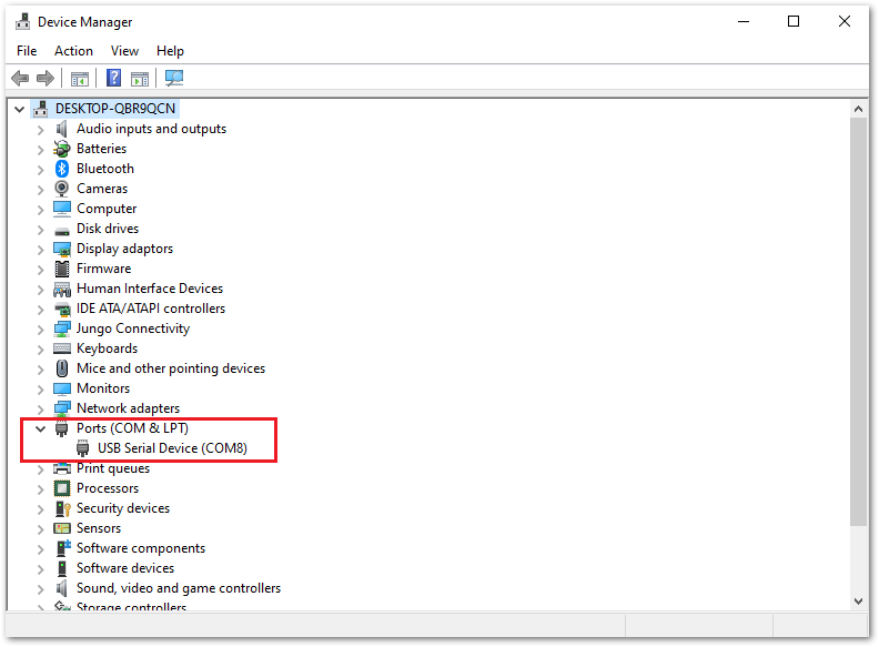 Figure 1: Windows Device Manager Ports (COM & LPT)
Code Explanation RAK4631 Example
1.1 Initializes WisBlock RAK5811 Module
- Enable booster
/* WisBLOCK 5811 Power On*/
pinMode(WB_IO1, OUTPUT | PULLUP);
digitalWrite(WB_IO1, HIGH);
1.2 Initializes Analog Input Pin and Configure ADC
- The
analogReferencefunction configure the reference voltage used for analog input. The reference voltage is the value used as the top of the input range. - The
analogOversamplingis a method to achieve a higher resolution without using an external ADC.
pinMode(WB_A1, INPUT_PULLDOWN);
analogReference(AR_INTERNAL_3_0);
analogOversampling(128);
1.3 Get ADC Samples
- At the end of sampling, the sketch calculates the average ADC.
for (i = 0; i < NO_OF_SAMPLES; i++)
{
    mcu_ain_raw += analogRead(WB_A1);
}
average_raw = mcu_ain_raw / i;
1.4 Process ADC Samples
- Calculate raw voltage based on ADC reference and resolution
- Reduce input signal to 6/10
mcu_ain_voltage = average_raw * 3.0 / 1024;   // ref 3.0V / 10bit ADC

voltage_sensor = mcu_ain_voltage / 0.6;     // WisBlock RAK5811 (0 ~ 5V).   Input signal reduced to 6/10 a

depths = (voltage_sensor * 1000 - 574) * 2.5;   //Convert to millivolt. 574mv is the default output from sensor

Serial.printf("-------average_value------ = %d\n", average_raw);
Serial.printf("-------voltage_sensor------ = %f\n", voltage_sensor);
Serial.printf("-------depths------ = %d mm\n", depths);
Code Explanation RAK11200 Example
1.1 Initializes WisBlock RAK5811 Module
- Enable booster
  /* WisBLOCK 5811 Power On*/
pinMode(WB_IO1, OUTPUT | PULLUP);
digitalWrite(WB_IO1, HIGH);
1.2 Initializes Analog Input and Configure ADC
- The function
adcAttachPinattach a GPIO pin to ADC. - The function
analogSetAttenuationsets the input attenuation for all ADC pins. The default value is ADC_11db. - The function
analogReadResolutionset the size (bits) of the ADC. The default value is 12-bit resolution.
adcAttachPin(WB_A1);
analogSetAttenuation(ADC_11db);
analogReadResolution(12);
1.3 Get ADC Samples
- At the end of sampling, the sketch calculates the average ADC.
for (i = 0; i < NO_OF_SAMPLES; i++)
{
    adc_raw += analogRead(sensor_pin);
}
average_adc_raw = adc_raw / NO_OF_SAMPLES;
1.4 Process ADC Samples
- The function
esp_adc_cal_raw_to_voltage(average_adc_raw)convert adc_raw value to voltage in mV.
voltage_mcu_ain = esp_adc_cal_raw_to_voltage(average_adc_raw);
voltage_sensor = voltage_mcu_ain / 0.6;   //WisBlock RAK5811 (0 ~ 5V). Input signal reduced to 6/10 and output
depths = (voltage_sensor * 1000 - 574) * 2.5; //Convert to millivolt. 574mv is the default V output from sensor
ADC measurements will be noisier while WiFi is on, often due to poor power and/or signal filtering.
1.5 ADC Calibration API
Espressif provides a library (API) for ADC calibration that uses tables for comparison. You can find more details about ESP32 ADC calibration on Espressif ADC API.
