RAK4260 WisDuo Breakout Board Quick Start Guide
Prerequisites
The next two sections list the components and tools required to get started with the development board. While some components are included in the package, others need to be provided separately.
Before going through the steps in the installation guide of the RAK4260 Breakout Board, make sure to prepare the necessary items listed below:
Hardware Tools
- RAK4260 Breakout Board (provided) – including LoRa antenna, Dupont lines (13x)
- USB to UART adapter – CH340 for example (not provided)
- RAKDAP1 DAPLink Tool (not provided)
- Gateway in range, for testing (not provided)
- Windows PC (not provided)
Software Tools
Package Inclusions
- RAK4260 Breakout Board
- LoRa antenna
- Dupont lines (24x)
Product Configuration
Interface with RAK4260 Breakout Board
Before powering the RAK4260 Breakout Board, ensure the included LoRa antenna is installed. Failure to do so may damage the board.
USB to UART
- Connect the USB-to-UART adapter to the pin header on the RAK4260 using a set of 4 DuPont lines. Refer to Figure 1 for proper wiring guidance.
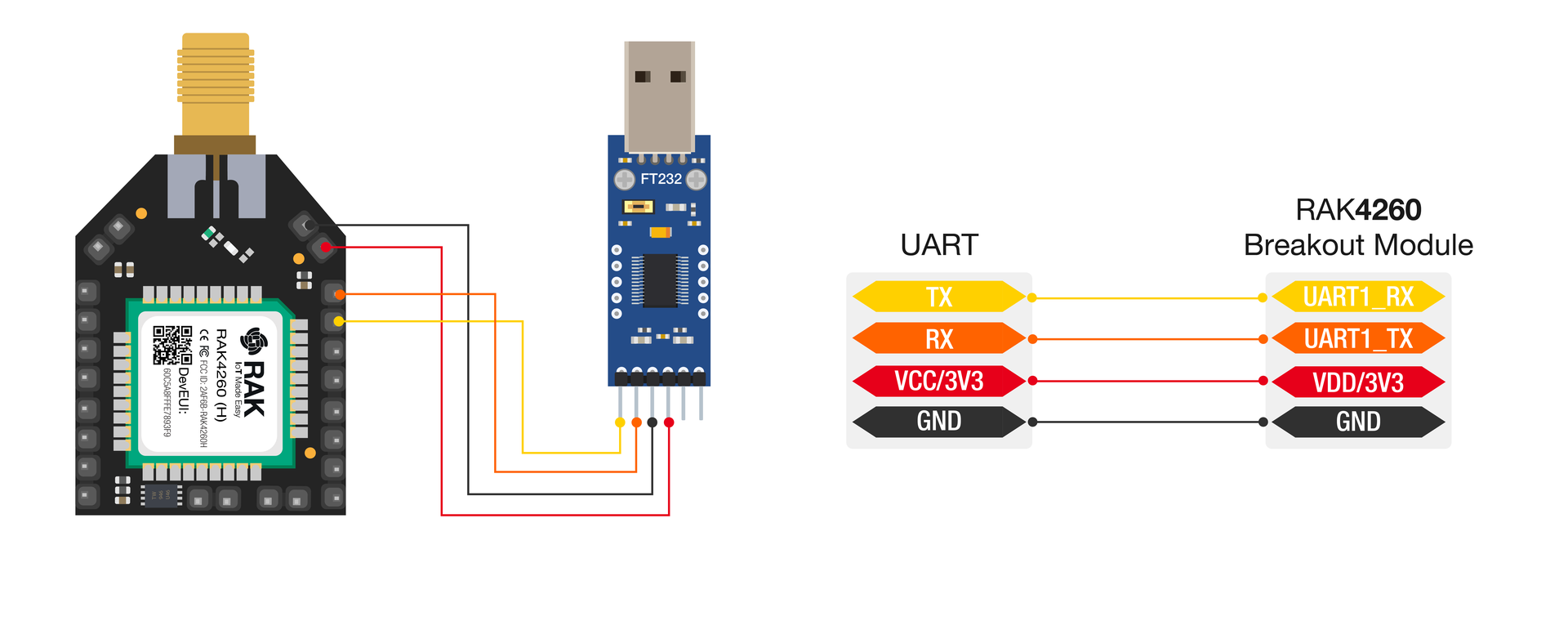 Figure 1: Powering up and interfacing with the board
-
Open the Device Manager by pressing
Windows+R, typingdevmgmt.msc, and pressing Enter. Alternatively, you can search fordevmgmt.mscin the Start Menu. -
Look for Ports (COM & LPT) and locate the entry named USB-SERIAL CH340. Note the COM port number, as you will need it to connect to the board. If you have a different model, the name should still include USB-SERIAL in some form.
Windows 10 should recognize the board and automatically install drivers. If you didn't find any port with the name USB-Serial CH340, make sure to install the CH340 Drivers in your Windows PC.
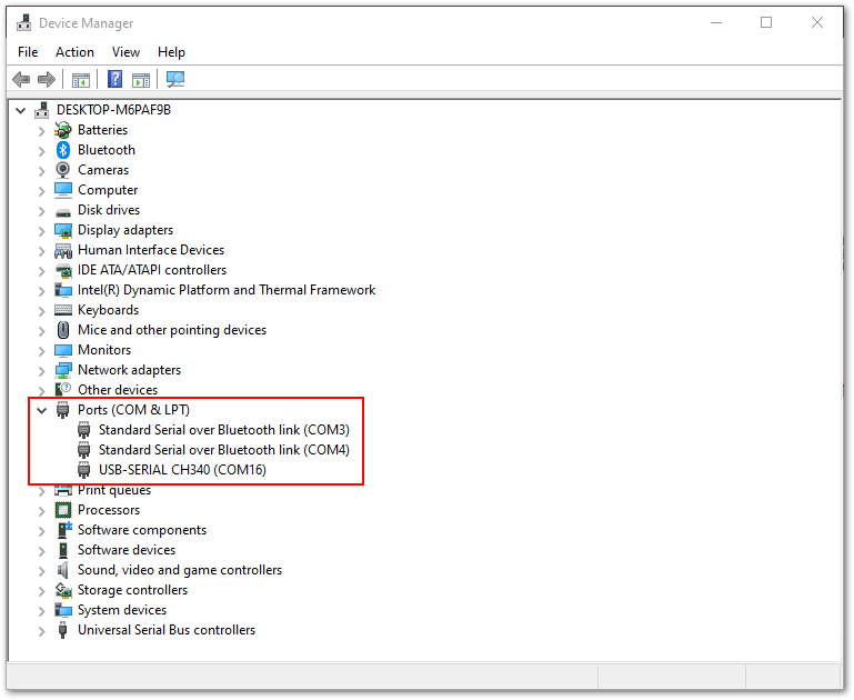 Figure 1: COM Port settings
- Open the RAK Serial Port Tool. Select the COM Port number (the one you noted in the previous step) and set the Baud Rate to 115200. Click OPEN, and you should be connected to the board and be able to send commands.
 Figure 1: Configure the RAK Serial Port Tool
DAPLink Connection
Connect the tool as shown in Figure 4 and Figure 5.
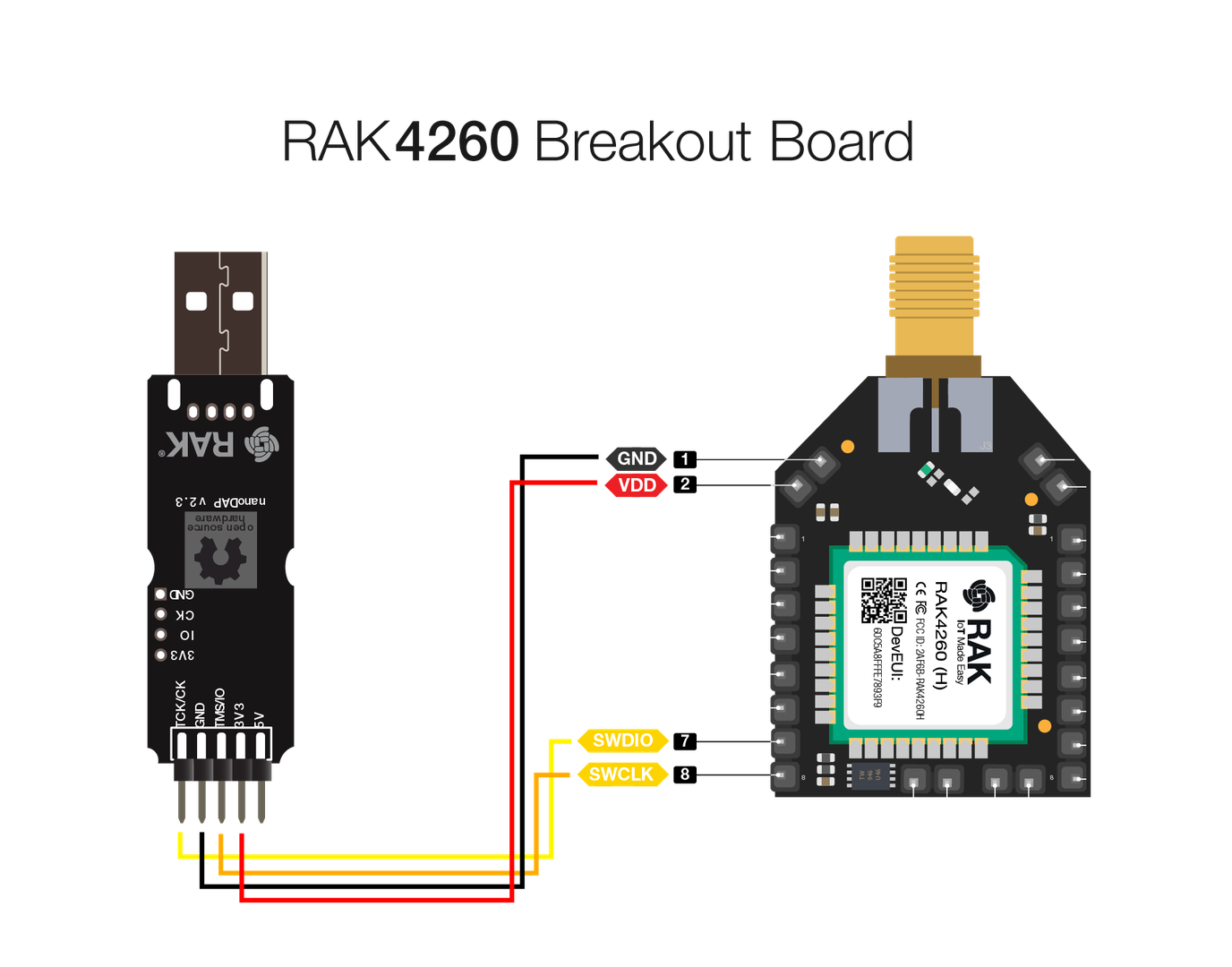 Figure 1: DAPLink to RAK4260 Breakout Board
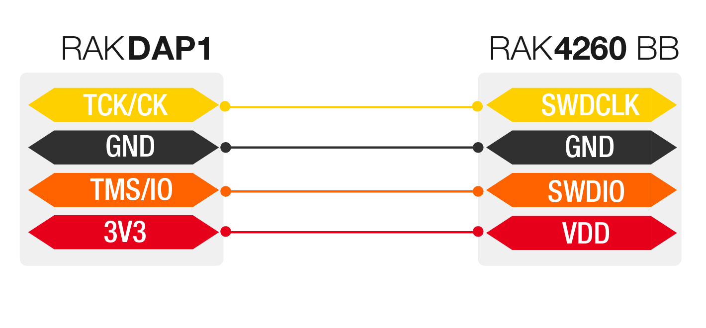 Figure 1: DAPLink connection
Connect with The Things Network (TTN)
The Things Network enables low-power devices to connect to long-range gateways, facilitating data exchange with applications over an open-source, decentralized network. Learn more about it on the The Things Network website.
This section will guide you through connecting the RAK4260 Breakout Board to The Things Network (TTN).
- If you don't have an account yet, head on to the TTN site and create one. Once done, log in to your account and go to the console.
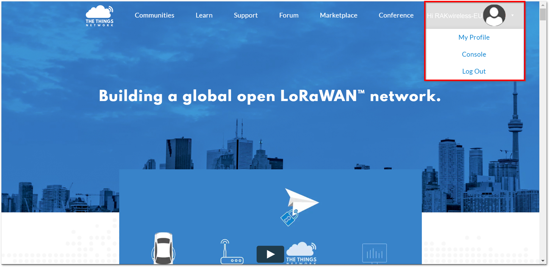 Figure 1: The Things Network Home Page
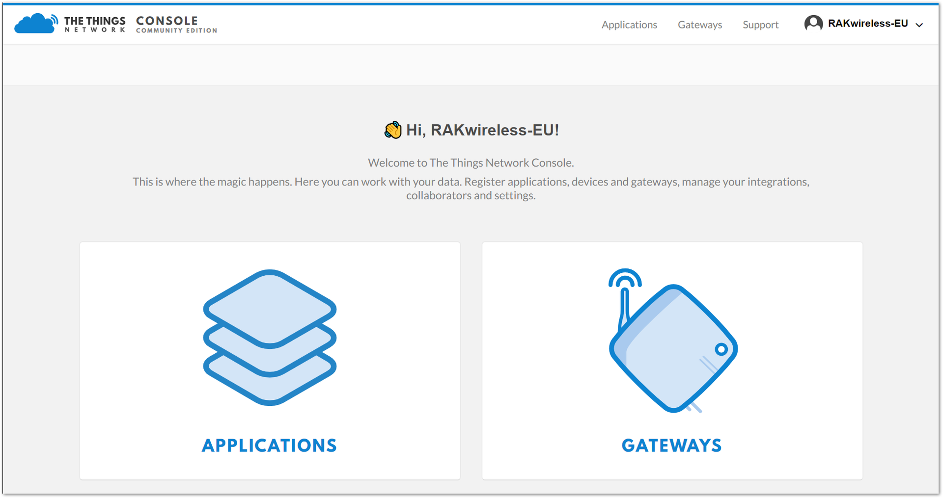 Figure 1: TTN Console Page
- Choose APPLICATIONS.
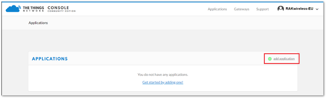 Figure 1: Application Page
Add an Application
- Click the add application button
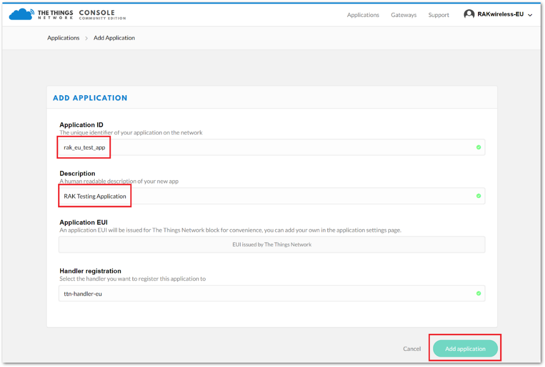 Figure 1: Add an Application
Here are the key points to consider when adding an application to TTN:
- Application ID: A unique identifier on the TTN network, written in lowercase with no spaces.
- Description: A short and concise human-readable description of your application.
- Application EUI: Automatically generated by TTN.
- Handler Registration: Select the handler to which you want to register this application.
- After filling in the necessary information, press the Add application. If the page is the same as shown in Figure 10, then you have successfully registered the application.
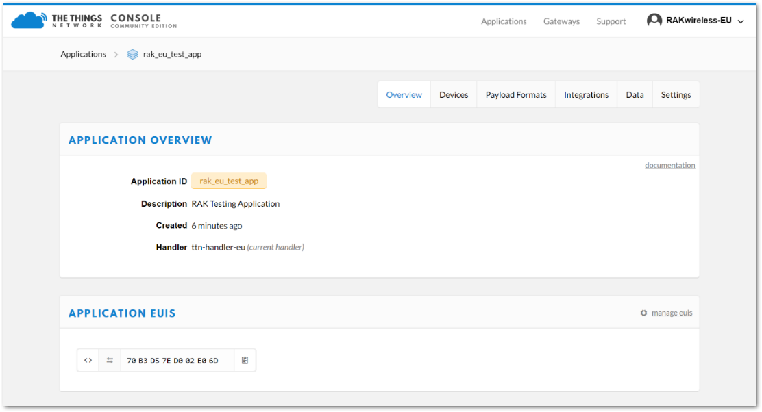 Figure 1: Application Overview
Register the Device
- Scroll down to the Devices section, or click the Devices button at the top.
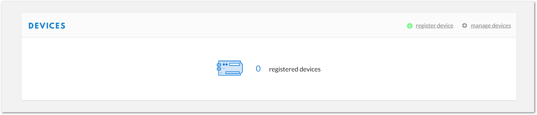 Figure 1: Device Section
- Click Register device.
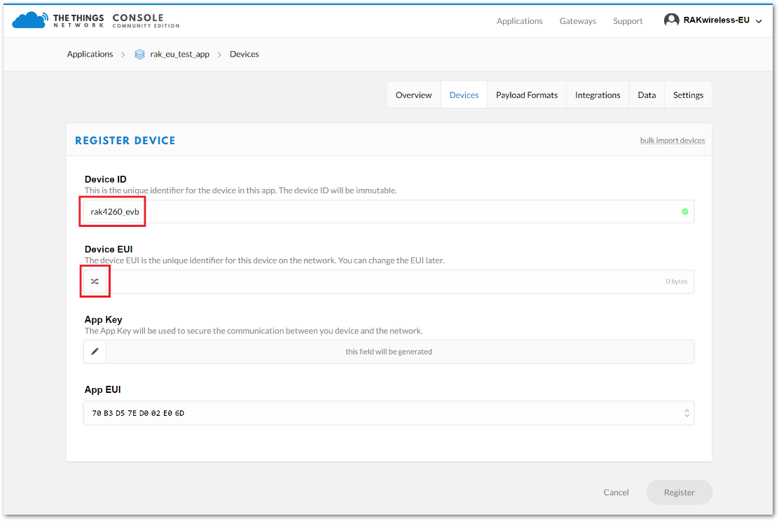 Figure 1: Add your Device
Here are the key details to note when registering your device:
- Device ID: A unique identifier for your RAK4260 Breakout Board within your application, which you must enter manually.
- Device EUI: A unique identifier for your device within the network, which can be changed later if needed.
- App Key: Used to secure communication between the device and the network.
- App EUI: A unique identifier for the application in which you are registering the device.
- Fill in the Device ID field and generate a random Device EUI by clicking the arrows. Leave the remaining fields unchanged, then click Register. Your device will now be registered under the corresponding application.
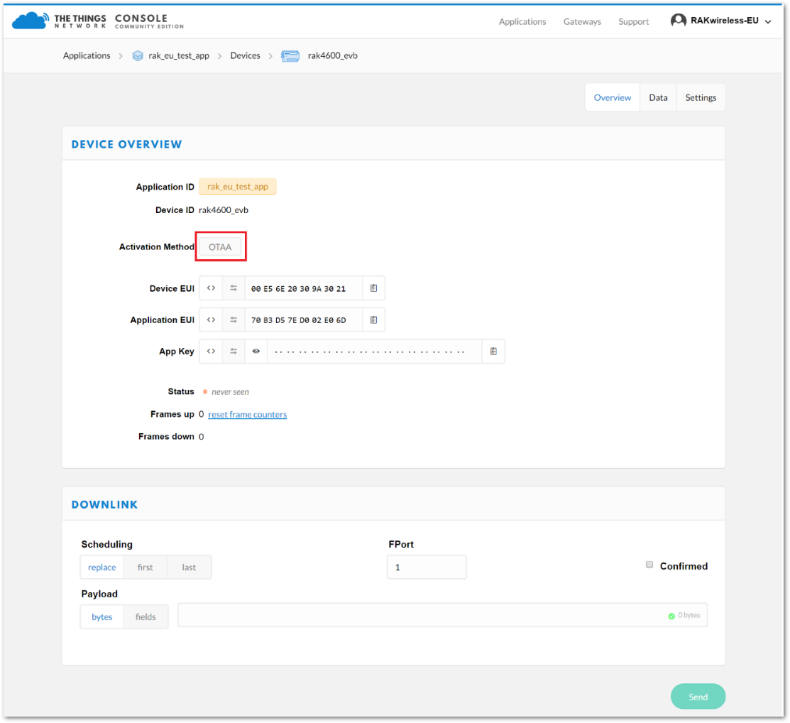 Figure 1: Device Overview
In the Device Overview, there are two options for the Activation Method: OTAA and ABP. The default option is OTAA as shown above.
OTAA Mode
OTAA stands for Over-The-Air Activation. While detailed information about OTAA is beyond the scope of this document, it is essential to understand that a device requires three parameters: Device EUI, Application EUI, and App Key. These parameters, as briefly explained in the previous section, must be set correctly for the LoRa Server to grant network access.
These parameters can be obtained from the Device Overview page, where they are conveniently grouped together.
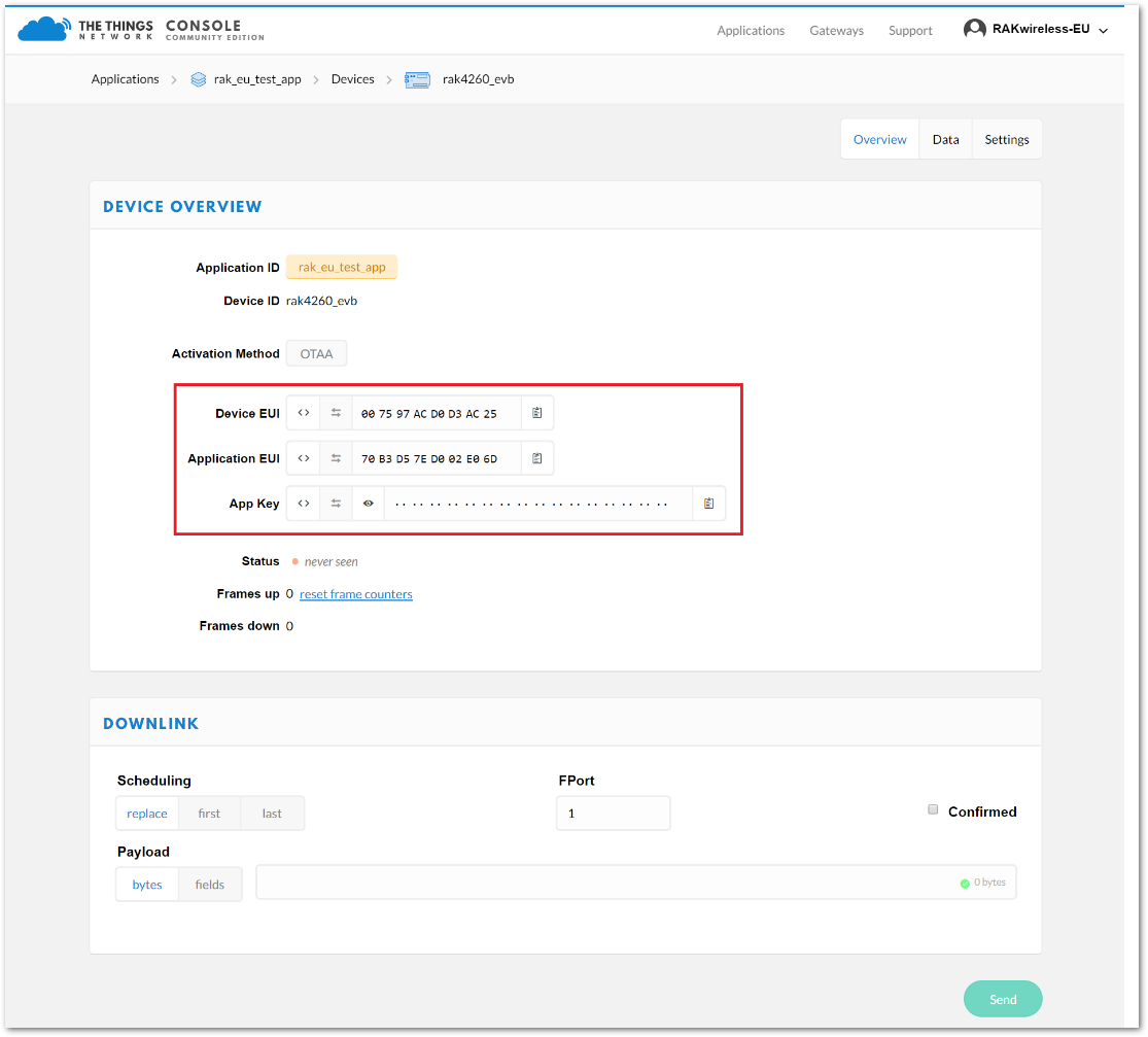 Figure 1: Device Overview Parameters
Since these values are randomly generated by TTN, you need to update your RAK4260 Breakout Board with them to register it on the network. As previously mentioned, this must be done directly in the source code, followed by compiling and flashing it to the device.
The next section will guide you through this process using Atmel Studio.
Parameter and Firmware Setup
Execute the following steps to connect your device with the TTN. Register and then fill in the parameters obtained upon registering.
Edit OTAA Parameters in the Code
- Open your Atmel Studio and navigate to the demo firmware you downloaded from the RAKwireless GitHub repository.
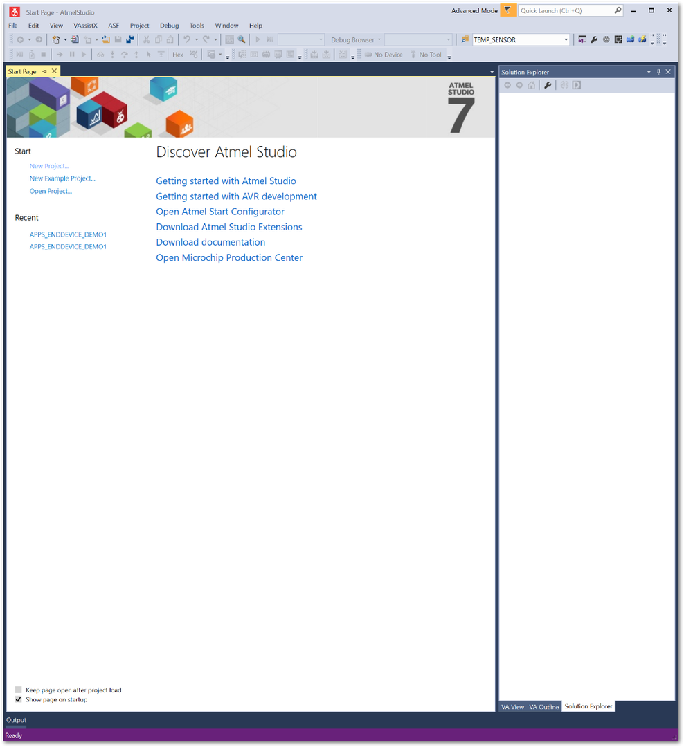 Figure 1: Atmel Studio main page
2 Go to File > Open > Project/Solution.
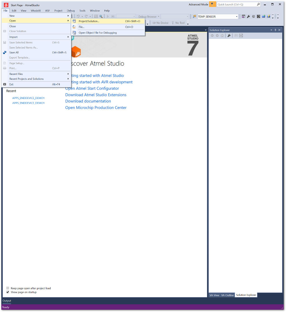 Figure 1: Open the sample project
- Go to the folder where you downloaded the GitHub repository and select the APPS_ENDDEVICE_DEMO1 project file (it is in the directory with the same name as the file). Then click Open.
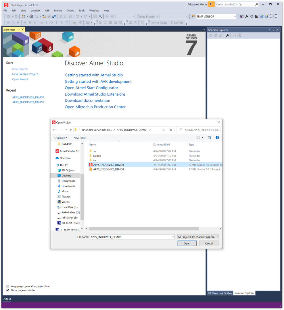 Figure 1: Demo firmware project file
- Once your project is loaded, you will see a file structure containing folders and files that you can edit. Copy the values of the three (3) parameters shown in Figure 14 and paste them into the
conf_app.hfile. This file is located in thesrcconfig folder, accessible through the Solution Explorer tree.
Here are the required parameters:
- Device EUI
- Application EUI
- Application Key
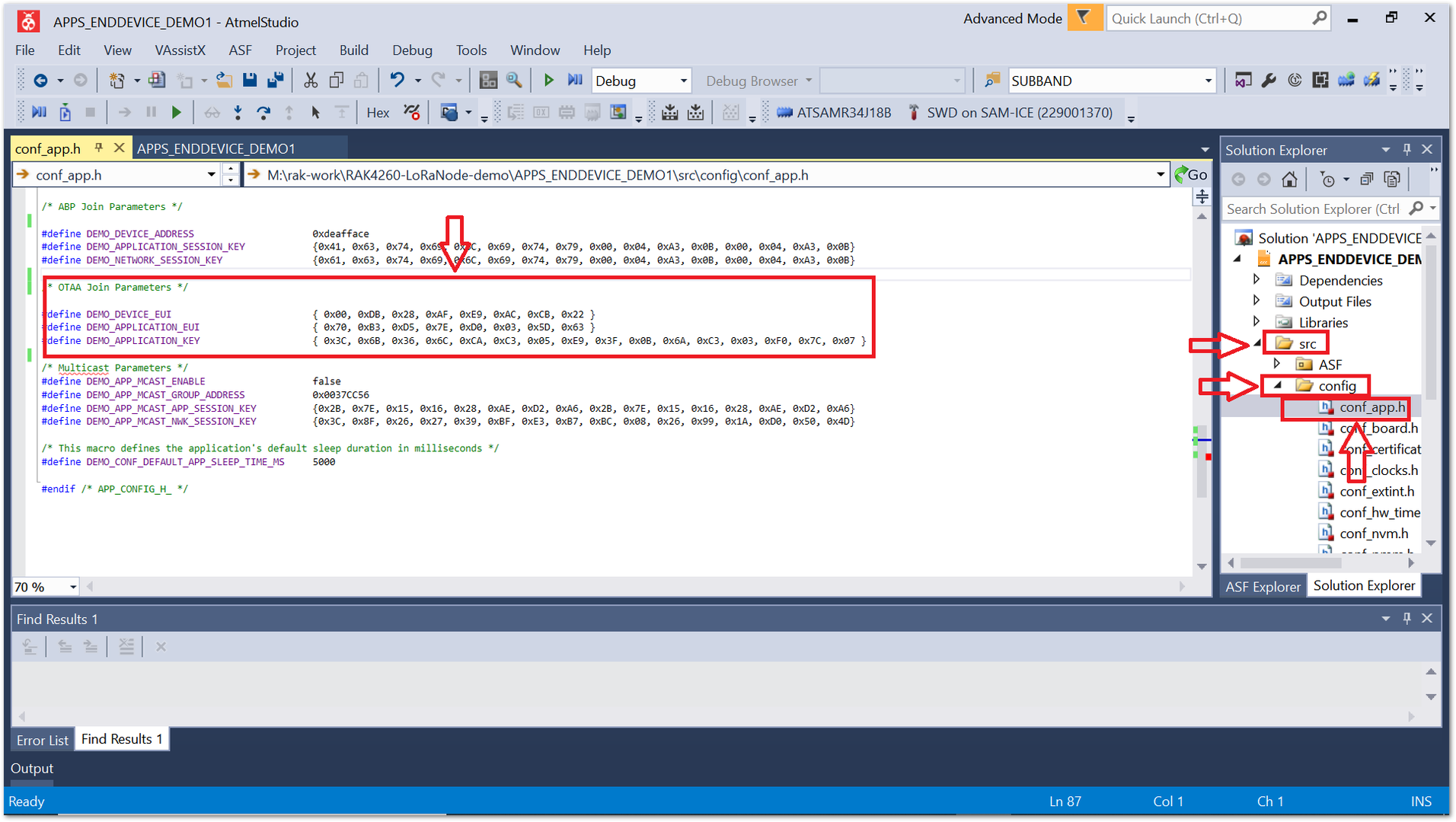 Figure 1: Device configuration file (OTAA parameters)
- After replacing the default values with those for the device registered with TTN, you can proceed to compile the project.
There is no need to edit anything else in order to compile the firmware that will allow you to connect to the TTN network.
Compile the Code
- Compile the code by going to the Build > Build Solution.
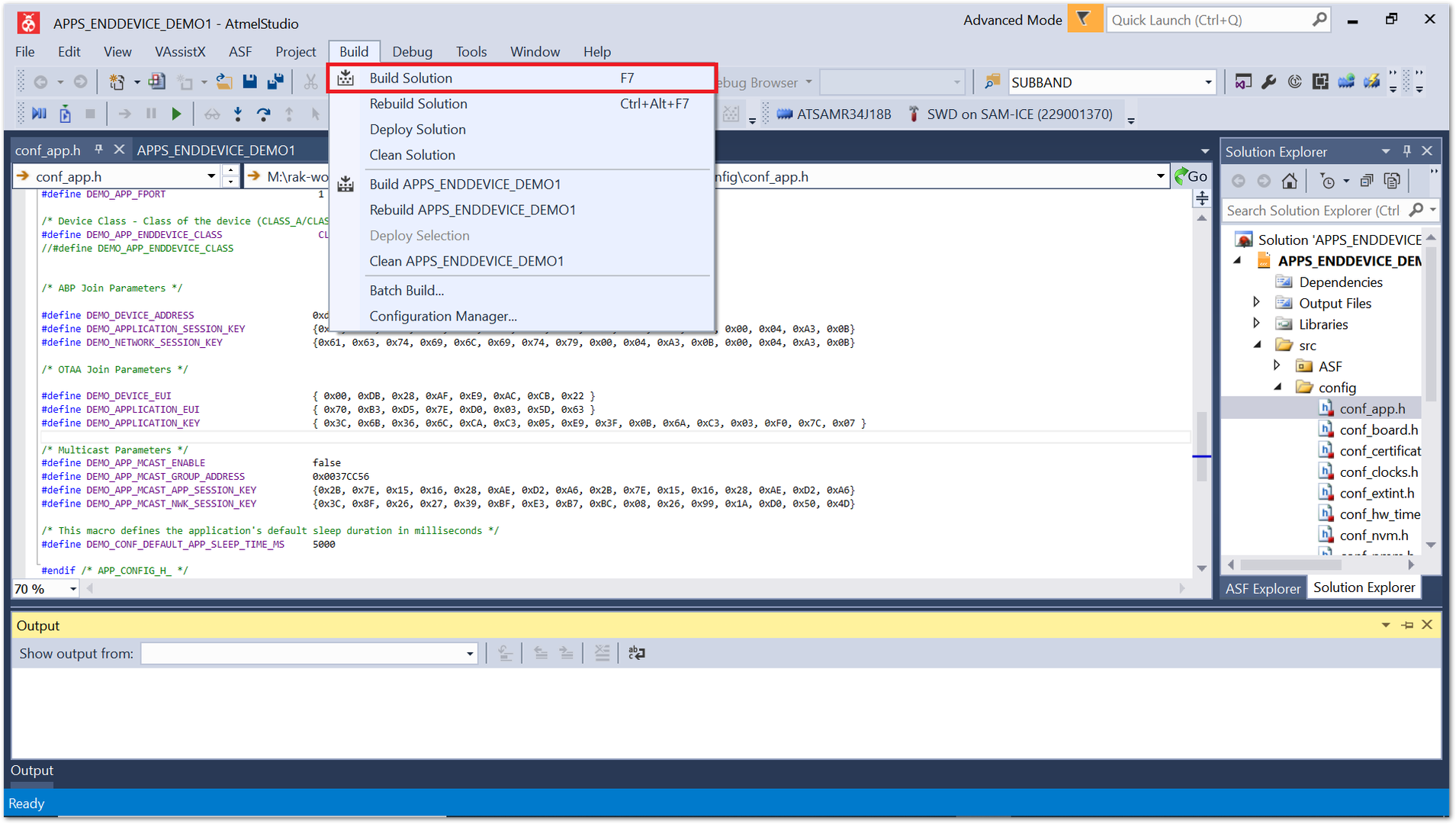 Figure 1: Compile the code
- The output should have no errors, as shown in Figure 20.
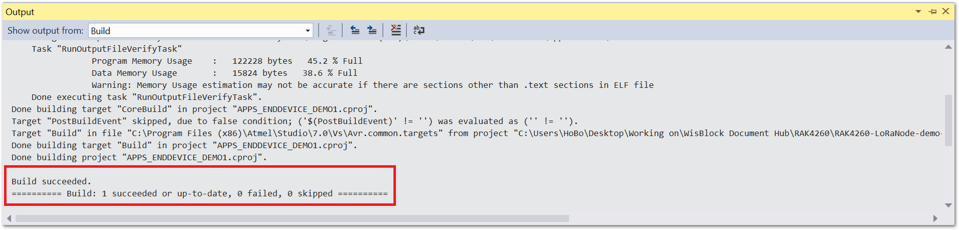 Figure 1: Compile the code
Flash the Firmware
- Find the output file in the Debug folder of the directory where you downloaded the firmware. Refer to Figure 21 for guidance.
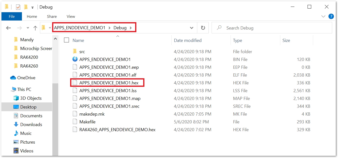 Figure 1: Firmware .hex file
- With the firmware now ready, proceed to flash it using the RAKDAP1 hardware tool and the pyOCD software tool.
Flash the Firmware Using RAKDAP1
Refer to the RAKDAP1 Flash and Debug Tool.
Connect to TTN
Connect the USB to the UART adapter to the pin header on the RAK4260 via a set of four (4) DuPont lines. Refer to the Interfacing with RAK4260 Breakout Board section for more details.
Regional Band and Join Network Setup
- When you open the RAK Serial Port Tool, it should display the details shown in Figure 22, provided it has been less than 5 seconds since the board was powered on. The firmware is designed to initialize with default settings 5 seconds after powering up.
EU868 is used for the region as an example. This section shows how to change the default region and connect with the network.
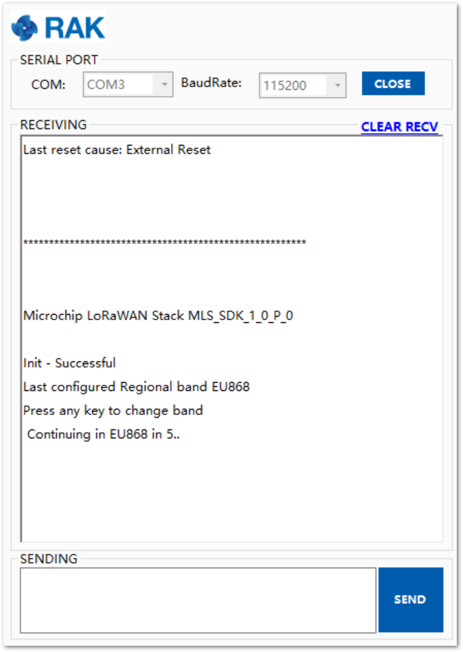 Figure 1: Start up default output
- After the 5-second period has elapsed, the current configurations will be reported. These configurations include:
- Class A
- OTAA
- Unconfirmed LoRa Frames
- Fport - 1
These settings are not adjustable at this stage. If you want to change them, you need to start over at the stage where you modify the firmware files before compiling them.
- Using Figure 23 as a reference, you will see a list of four (4) options. To navigate to the Main Menu, send the number 4.
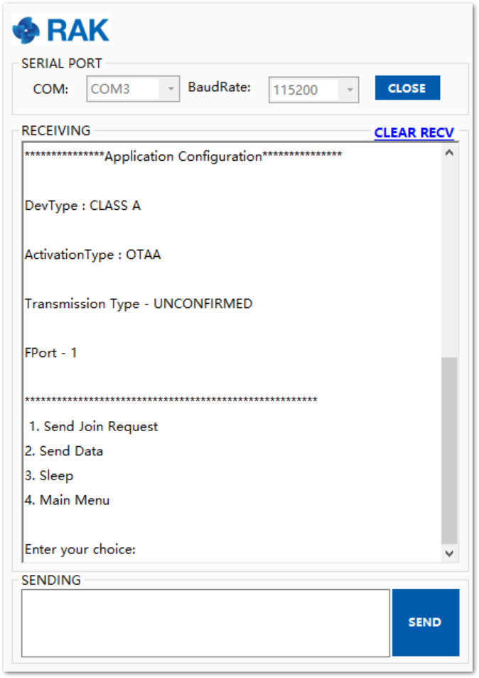 Figure 1: Configuration menu
- Send the number 1 to select the EU868 Regional Band. Alternatively, you can choose a different number based on your specific requirements.
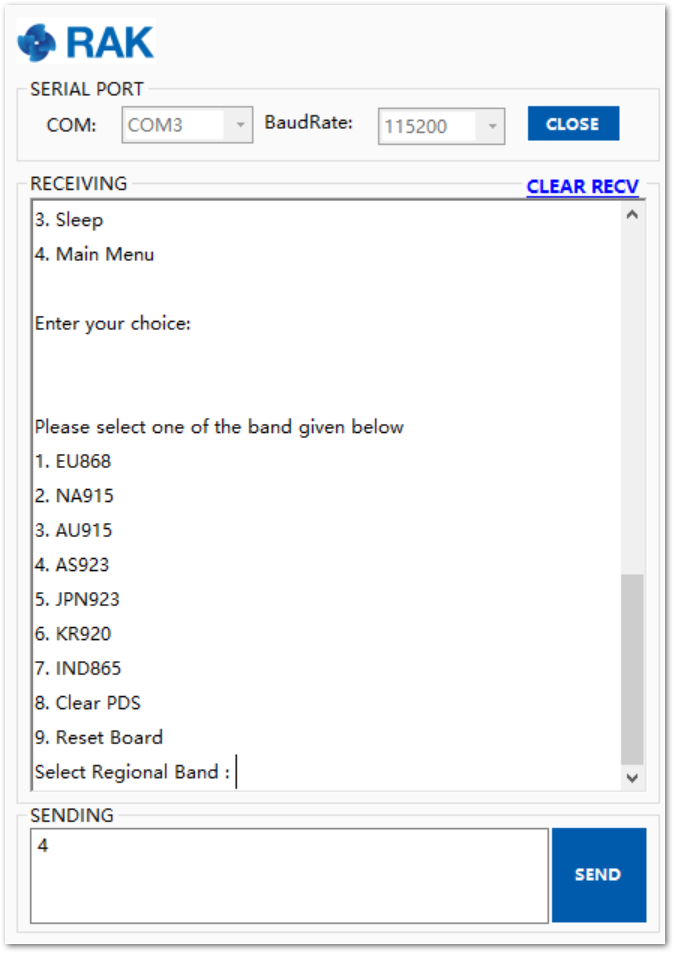 Figure 1: Band selection menu
- The device will automatically attempt to join the LoRaWAN network using the Device EUI, Application EUI, and Application Key configured in the firmware file.
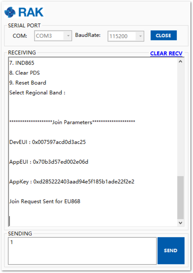 Figure 1: Network join parameters set
- If the device successfully joins the network, it will report the assigned Device Address, along with the parameters (e.g., Class A, OTAA). The Configuration Menu will then be displayed again, allowing you to send another command.
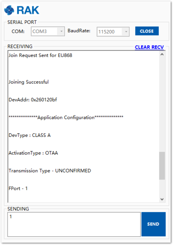 Figure 1: Successful network join
Uplink LoRa Frame Testing
- In the main menu, select Option 2 to send an uplink LoRa Frame.
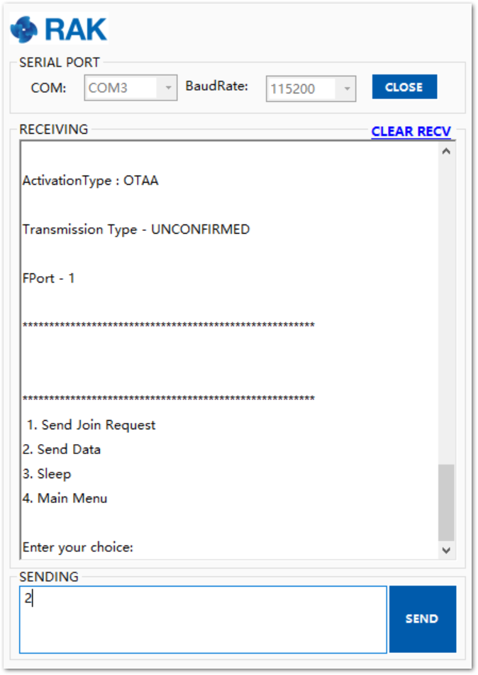 Figure 1: Send data to the server
The firmware uploaded into the RAK4260 Breakout Board is just an example. Thus, the data sent are just dummy temperature readings (the original Microchip code was for a board with an actual temperature sensor). It will be reported as output together with the transmission is successful, as shown in Figure 28.
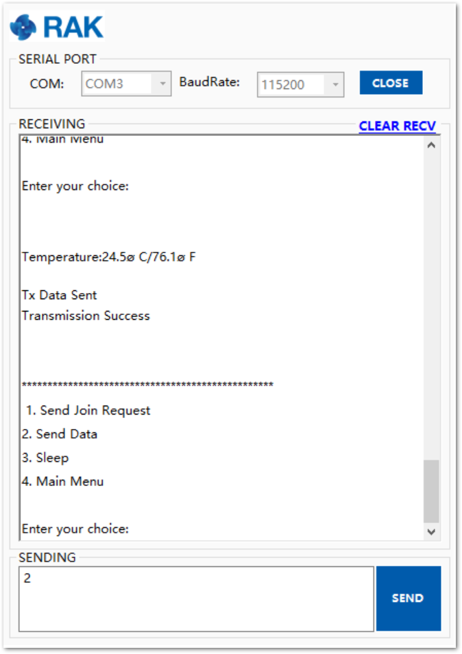 Figure 1: Send data to the server (successful)
This should be sufficient to prove that the board functions as intended, and it can send data over the network after successfully joining it. As this module is intended for development, the example firmware is limited to this functionality.
You can use this project as a base to develop a more complex firmware using the Microchip LoRaWAN Stack (MLS).