LoRa Module Low Level Development Reference
Overview
The product portfolio of the RAK LoRa node RAK4600 module. This module comes with a standard version of firmware that allows you to integrate quickly these modules in their solutions for LoRaWAN or LoRa P2P communication through the AT commands interface.
Further customization of the firmware can be done through the RUI compiler. At this layer, the customized firmware interface with the hardware through the RUI Core abstraction layer. In RAK we called this a secondary firmware development/customization.
Additionally, RAK offers a third alternative for advanced users who need to have deeper integration of their solutions with these modules. In this alternative, the customer could develop their own version of firmware that runs inside of the RAK modules.
How to Implement your App on RAK Module
Schematic
One of the essential aspects that allow customers to develop their own version of firmware is the module’s hardware schematic. This allows you to understand the module’s pinout, connections between the inner MCU and the LoRa transceiver.
There are two versions of the RAK4600 module: one for the high-frequency bands (i.e. 915MHz, 866 MHz) and one for the low-frequency bands (i.e.433 MHz). Moreover, RAK4600 shares the same connections between high-frequency and low-frequency models.
Porting LoRa Protocol Stack
When implementing the LoRa protocol stack, special attention must be paid to the SPI connections, since the LoRa transceivers are controlled by the MCU through an SPI interface. The important pins are SPI1_MISO, SPI1_MOSI, SPI_NSS, and SPI_CLK. Additionally, the DIO, RF switch, and RFI path are important, as well, to have a functioning LoRa communication.
After that, Real-Time Clock (RTC) must be properly configured in the MCU to ensure accurate timing of protocol stack during the runtime.
Finally, the protocol stack code can be added after other pins are configured.
Application
Once the porting protocol stack is ready, customers can focus on the development of their applications. There are two options:
a. Do not use the original bootloader that comes in RAK modules from the factory. In this case, you must provide your own version of bootloader.
b. Use RAK's bootloader and upgrade the custom firmware by using nRF Connect. You can download it from here: https://www.nordicsemi.com/Software-and-tools/Development-Tools/nRF-Connect-for-mobile
If you want to develop your own bootloader, you can refer to the schematic diagram and the datasheet of the MCU to implement the code. If you want to use RAK’s bootloader, continue reading the next section.
Bootloader
In any MCU, after the power is connected, the System bootloader is in charge to bootstrap all the necessary to set up the Interrupt Vector table, initialize variables, and jump to the address of the main() symbol.
The following image shows a usual memory map for an ARM Cortex M4, which is the architecture of RAK4600 MCU:
 Figure 1: Usual memory map for an ARM Cortex M4 MCU
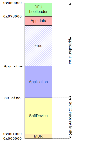
The flash memory section sits between the address 0x0800 0000 and 0x080X 0000. The X depends on the different models of MCU.
In the case of the RAK4600 module, its internal MCU is based on the nRF52832, the bootloader involves security verification. You must use Nordic SDK to compile your own security bootloader. The Nordic SDK version we use is 15.0.0 nrf5 SDK. The relevant routines can be found at examples/dfu/secure_ bootloader” sample code of Nordic SDK.
