RAK4600 Module Quick Start Guide
This guide covers the following topics:
- The Things Stack (TTN V3) OTAA Guide
- RAK4600 OTAA AT Commands for The Things Stack
- The Things Stack (TTN V3) ABP Guide
- RAK4600 ABP AT Commands for The Things Stack
- Chirpstack OTAA Guide
- RAK4600 OTAA AT Commands for Chirpstack
- Chirpstack ABP Guide
- RAK4600 ABP AT Commands for Chirpstack
- LoRa P2P Guide
- Updating RAK4600 FW Procedure
Prerequisites
What Do You Need?
Before going through the step in the installation guide of the RAK4600 WisDuo LPWAN Module, make sure to prepare the necessary items listed below:
Hardware Tools
- RAK4600 WisDuo LPWAN+BLE Module
- Windows PC
- USB to TTL adapter
- RAKDAP1 Flash and Debug Tool
- LoRaWAN gateway in range
Software Tools
Definition of Terms
List of Acronyms
| ABP | Activation-By-Personalization |
| BLE | Bluetooth Low Energy |
| DFU | Device Firmware Upgrade |
| EUI | Extender Unique Identifier |
| LoRa | Long Range |
| OTAA | Over-The-Air-Activation |
| TTN | The Things Network |
| P2P | Peer-to-peer communication |
| SWD | Serial Wire Debug |
Product Configuration
Interfacing with RAK4600
In this section, a RAK4600 module is used for demonstration. Use a USB to TTL adapter to connect to the module. In case the RAK4600 module is mounted on an evaluation board or a custom PCB, use the appropriate interface to connect to the serial port.
Before powering the RAK4600 Module, you should install the LoRa and BLE Antenna first. Not doing so might damage the board.
Use Figure 1 as a reference to connect the antennas.
 Figure 1: RAK4600 Module antenna connection
 - Connect the RAK4600 to USB to the TTL adapter, as shown in Figure 2.
In general, the pin marked as TX of the adapter must be connected to the USART1_RX pin of the RAK4600, and the RX pin of the adapter connects to the RAK4600 USART1_TX pin.
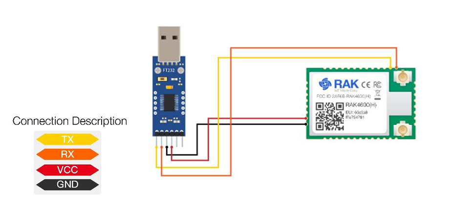 Figure 1: RAK4600 module connection
-
Open RAK Serial Port Tool. Any serial communication tool will work, but it is recommended to use the RAK Serial Port Tool.
-
Configure the serial communication tool by selecting the proper port of the computer UART port and configure the link as 115200 baud, 8 bits, no parity bit, and 1 stop bit.
- Choose the correct COM Port number for your device. Go to your Device Manager by pressing Windows + R and type
devmgmt.mscor search in the Start Menu.
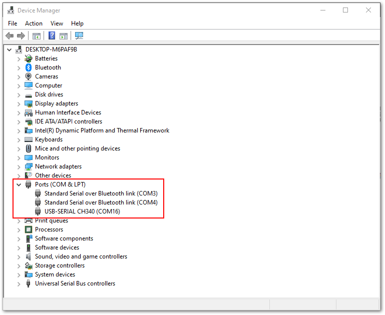 Figure 1: Device Manager
- Look for Ports (COM & LPT). Find the name of your USB UART Module driver and take note of the COM Port Number.
- The RAK4600 console output can now be read in the RAK serial port tool, as shown in Figure 4.
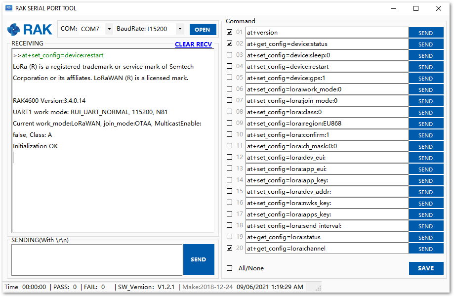 Figure 1: RAK4600 on RAK Serial Port Tool
Configure the RAK4600
Through UART
To connect the RAK4600 module to a LoRa P2P connection or a LoRaWAN network, the module must be configured, and the LoRa parameters must be set by sending AT commands through the UART interface.
Connect the RAK4600 module to the computer as described in the previous section. Using the serial communication tool, it is possible to send commands to the RAK4600. For example, sending the at+version will display the current firmware version, as shown in Figure 5.
The full set of RAK4600 AT commands can be found in Appendix I.
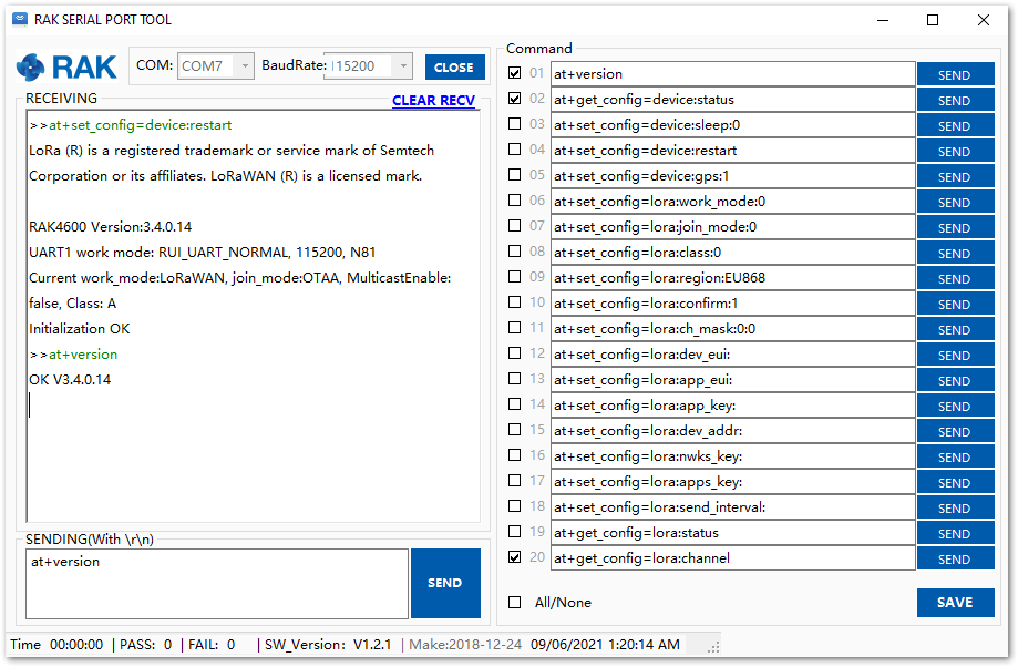 Figure 1: at+version command response
Through the BLE Interface
To configure the RAK4600 through BLE, execute the following steps.
- Install the “nRF Connect” or the “nRF Master Control Panel (BLE)” app provided by Nordic Semiconductor.
- Open the app on the mobile device and scan for BLE devices.
- Reset the RAK4600 module. After a few seconds, a list of BLE devices will be shown. The RAK4600 is listed as “RUI-XX: XX: XX".
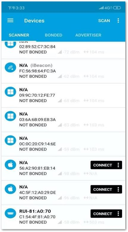 Figure 1: Nordic app scan for BLE devices
Connect within 60 seconds after resetting the RAK4600. After that time, the BLE broadcast will be stopped.
- After pressing the “CONNECT” button, a list will be displayed, as shown in Figure 7.
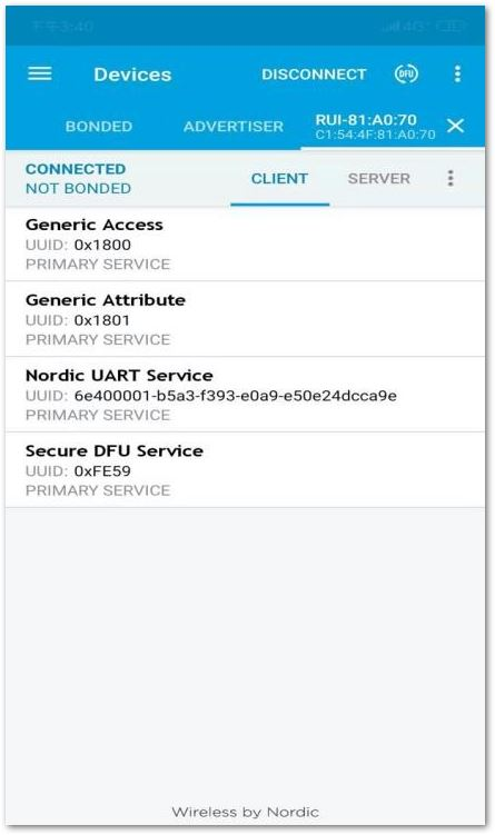 Figure 1: Options to connect to the RAK4600
- Select the service named “Nordic UART Service”.
- To receive data from mobile, enable notification on TX Characteristic by clicking on the arrow.
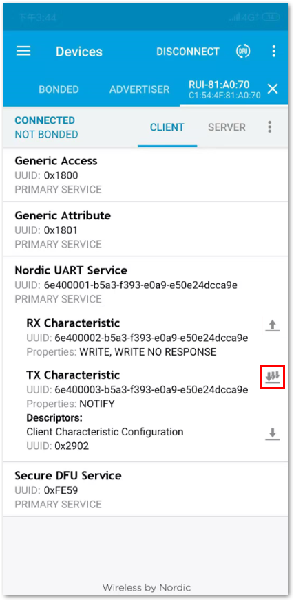 Figure 1: Enable notifications from mobile phone
- Write a value on RX Characteristic by clicking on the arrow.
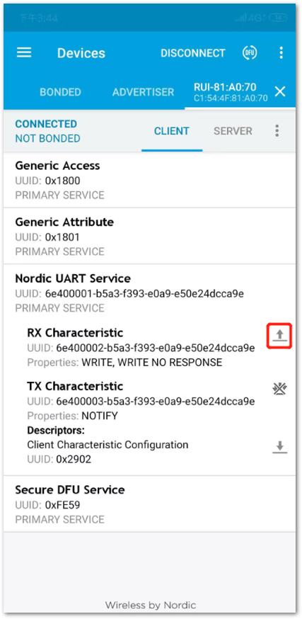 Figure 1: Send AT command
- A small input window will pop up. This is where you will input the AT commands.
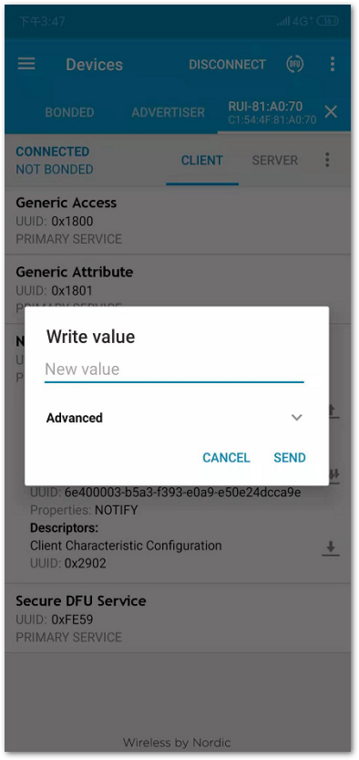 Figure 1: nRF app AT command input window
-
Send AT commands to RAK4600 in this dialog.
- For example, to check the current firmware version, type “
at+version” then click on the “SEND” button.
- For example, to check the current firmware version, type “
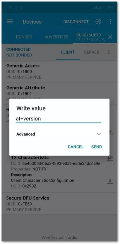 Figure 1: nRF app, send at command over BLE
The console output shall be read on the TX Characteristic of the App.
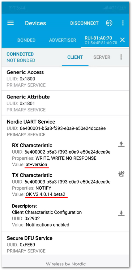 Figure 1: AT response over BLE
Connecting to The Things Stack (TTN V3)
This section will show how to connect the RAK4600 module to The Things Stack (TTN V3) platform.
 Figure 1: The Things Stack diagram
As shown in Figure 13, The Things Stack is an open-source LoRaWAN Network Server suitable for global, geo-distributed public and private deployments as well as for small, local networks. The architecture follows the LoRaWAN Network Reference Model for standards compliancy and interoperability. This project is actively maintained by The Things Industries.
LoRaWAN is a protocol for low-power wide-area networks. It allows for large-scale Internet of Things deployments where low-powered devices efficiently communicate with Internet-connected applications over long-range wireless connections.
The RAK4600 module can be part of this ecosystem as a device, and the objective of this section is to demonstrate how simple it is to send data to The Things Stack using the LoRaWAN protocol. To achieve this, the RAK4600 module must be located inside the coverage of a LoRaWAN gateway connected to The Things Stack server.
Registration to TTN and Creating LoRaWAN Applications
The first step is to go to The Things Network platform and select a cluster, as shown in Figure 14. The Things Industries adds more clusters from time to time, so select the one closes to your location. In this guide, Europe 1 is selected.
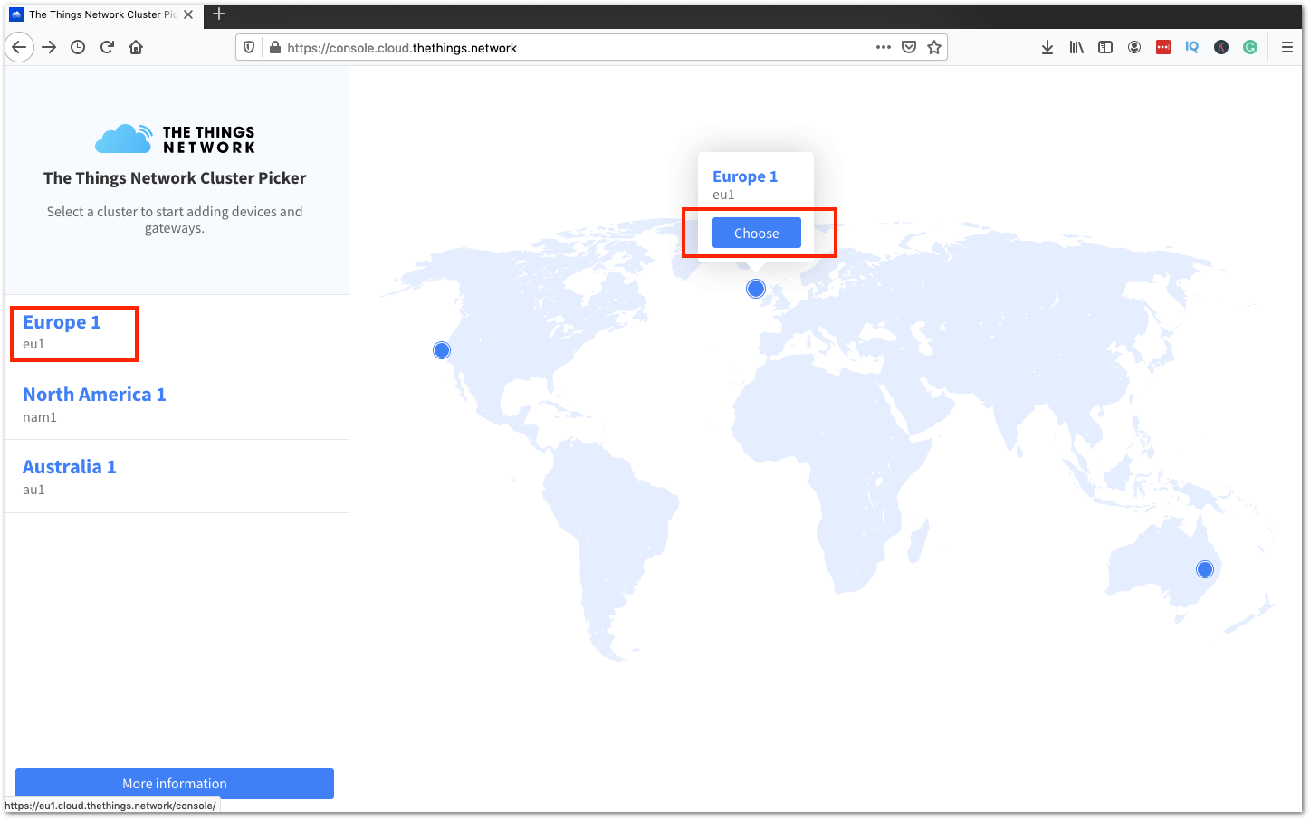 Figure 1: Selecting Cluster in TTN V3
You can use the same login credentials on the TTN V2 if you have one. If you have no account yet, you need to create one.
- To register as a new user to TTN, click on Login with The Things ID, then select register on the next page, as shown in Figure 15 and Figure 16.
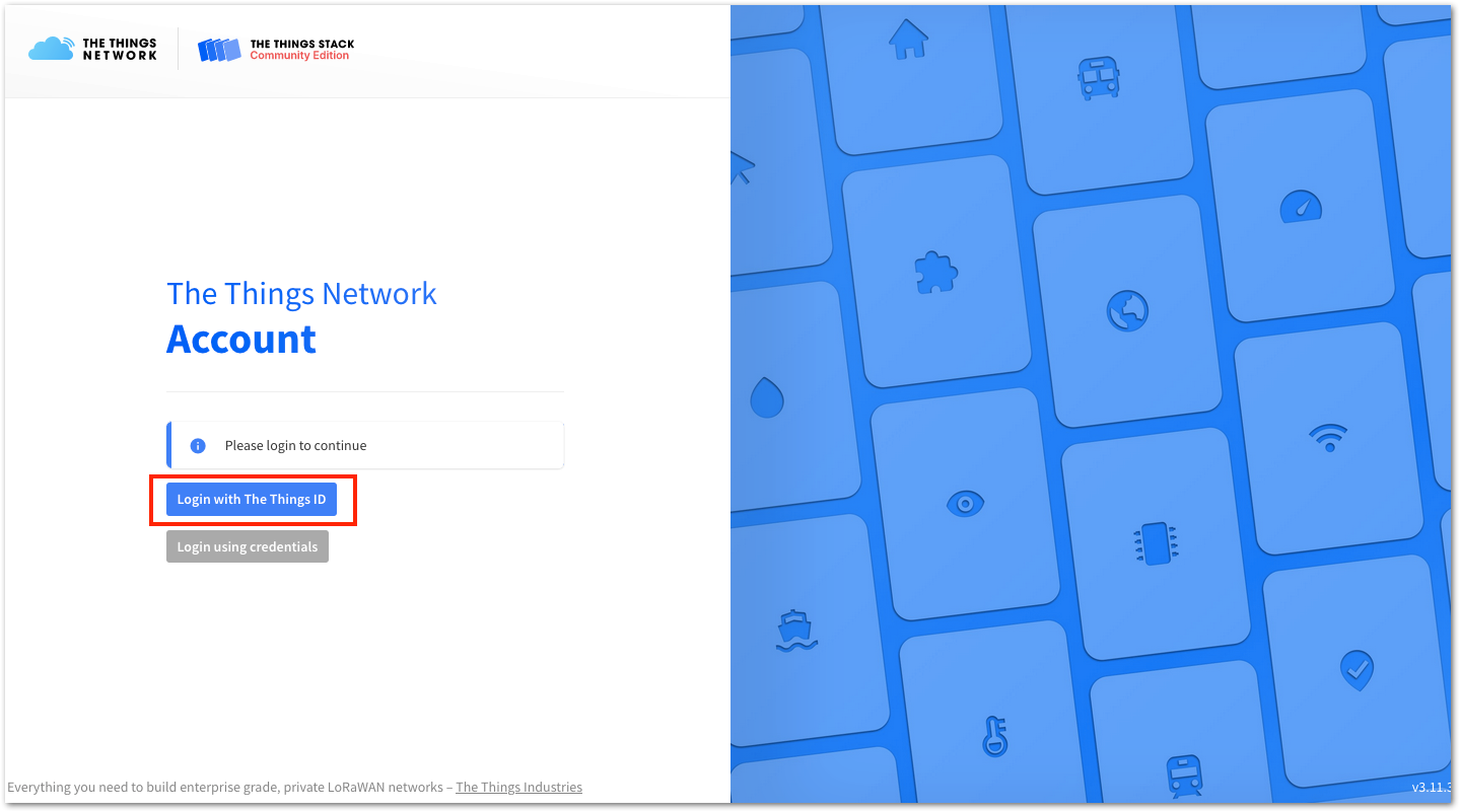 Figure 1: Login using TTN account
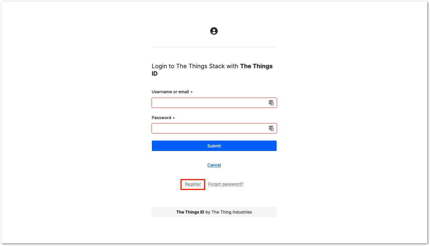 Figure 1: Registration of new account
-
You should now be on the step of creating your TTN account. Fill in all the necessary details and activate your account.
-
After creating an account, log in to the platform using your username/email and password, then click Submit, as shown in Figure 17.
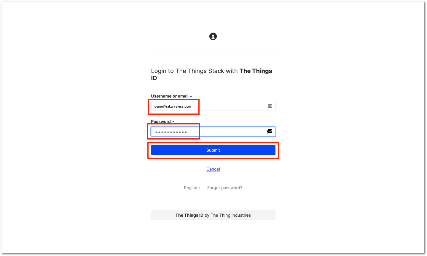 Figure 1: Logging in to TTN platform
- Click Authorize to proceed.
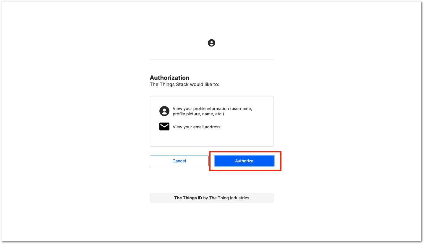 Figure 1: Authorization to TTN
- Now that you are logged in to the platform, the next step is to create an application. Click Create an application.
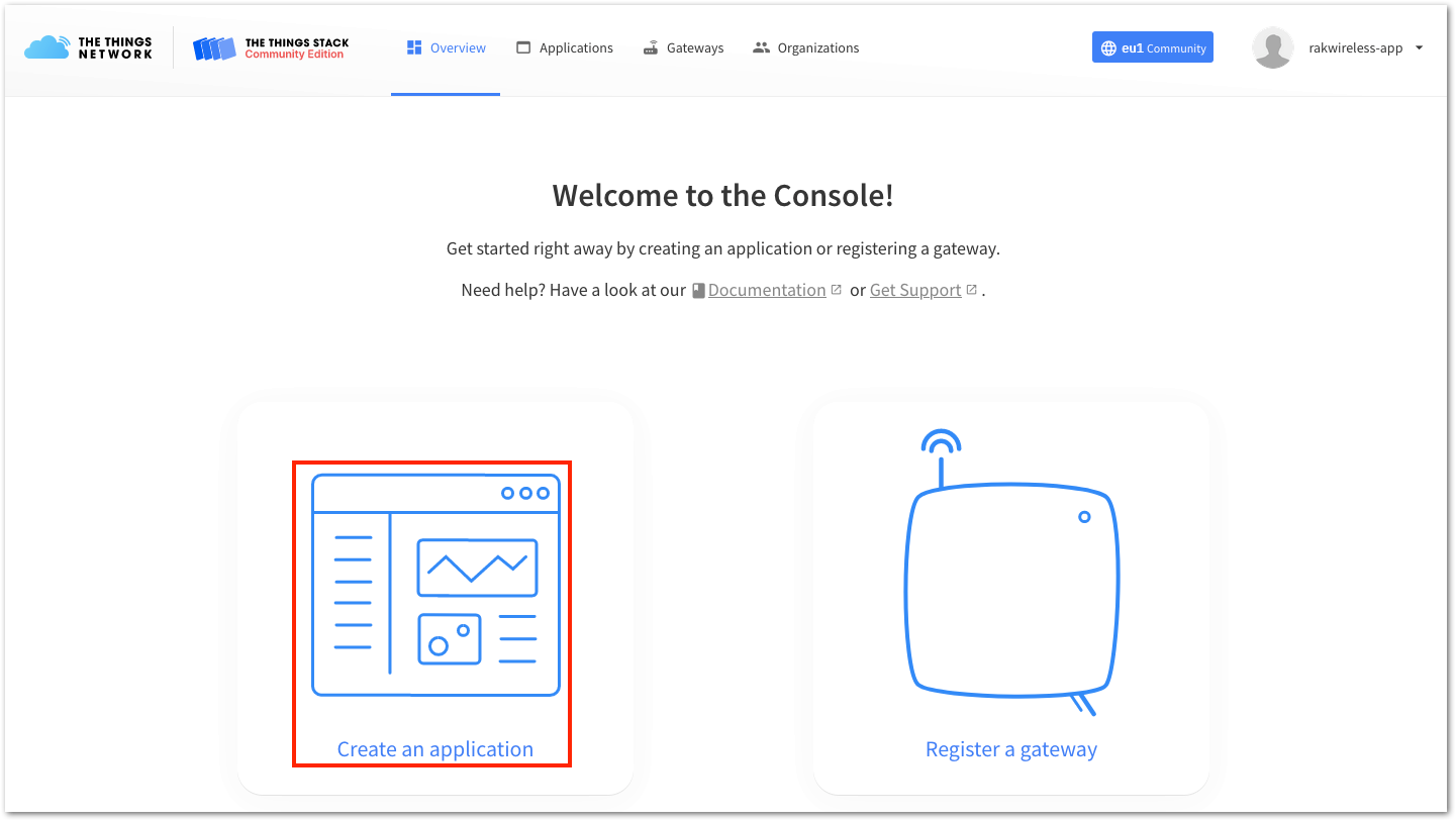 Figure 1: Creating TTN application for your LoRaWAN devices
- To have an application registered, input first the specific details and necessary information about your application, then click Create application.
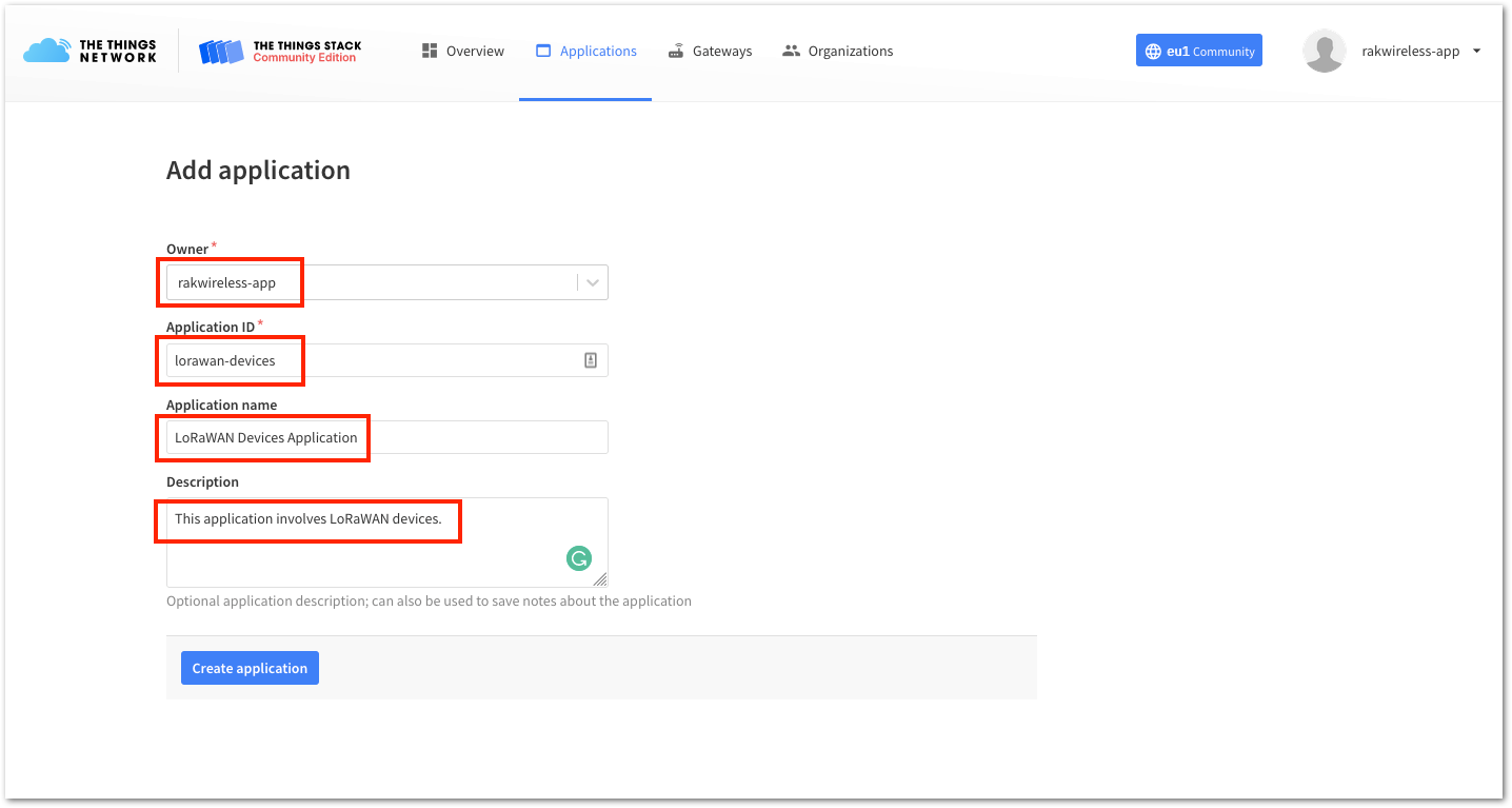 Figure 1: Details of the TTN application
If you have no error on the previous step, you should now be on the application console page. The next step is to add end-devices to your The Things Stack application. LoRaWAN specification enforces that each end device has to be personalized and activated. There are two options in registering devices depending on the activation mode selected. Activation can be done either via Over-The-Air-Activation (OTAA) or Activation-By-Personalization (ABP).
Once you have the application in The Things Stack (TTN V3), you need to ensure that you are in coverage of a LoRaWAN gateway that is registered to The Things Stack (TTN V3) as well. Without the coverage of that LoRaWAN gateway, you cannot activate any device that you will register in your application.
RAKwireless has LoRaWAN gateways that you can connect to The Things Stack (TTN V3) if no LoRaWAN gateway coverage is available in your location.
The Things Stack OTAA Device Registration
- Go to your application console to be able to register a device. To start adding an OTAA end device, click + Add end device, as shown in Figure 21.
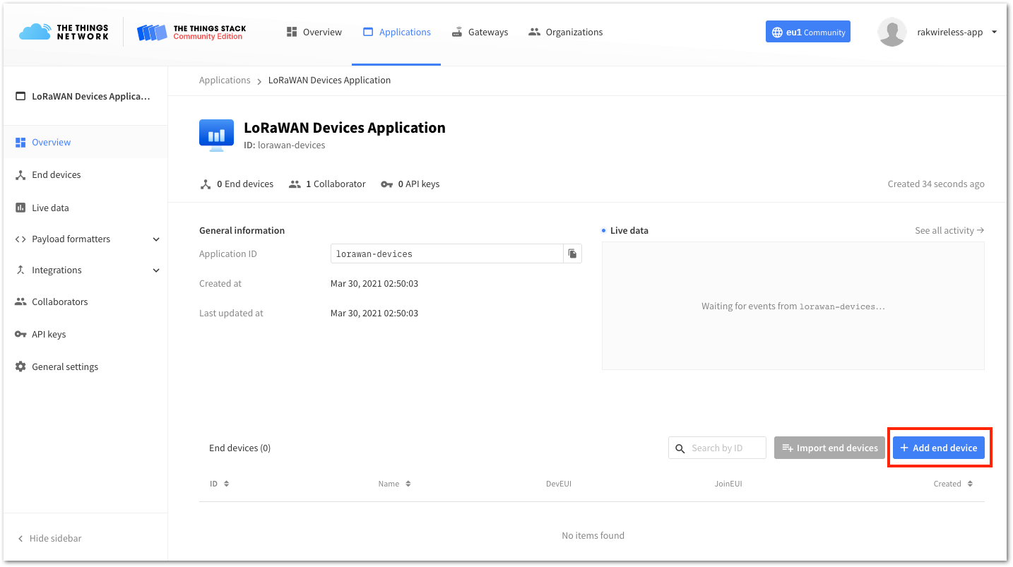 Figure 1: Add end device
- To register the module, you need to click first Manually then configure the activation method by selecting Over the air activation (OTAA) and compatible LoRaWAN version, then click the Start button, as shown in Figure 22 and Figure 23.
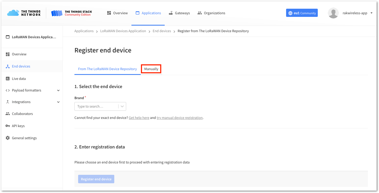 Figure 1: Manually register device to The Things Stack
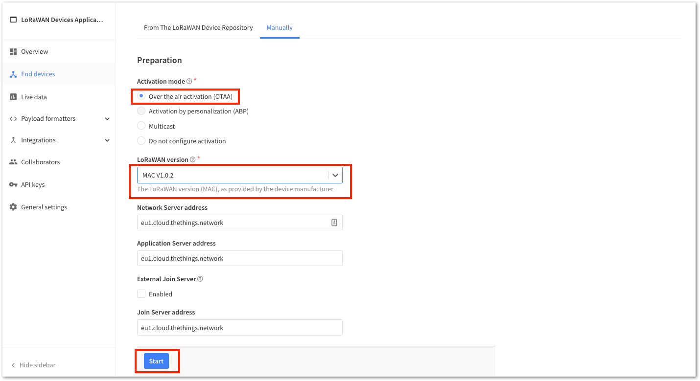 Figure 1: Device activation configuration
- Then, input a unique End device ID and EUIs (DevEUI and AppEUI), as shown in Figure 24. Check if your module has a DevEUI on sticker or QR that you can scan, then use this as the device unique DevEUI.
Optionally, you can add a more descriptive End device name and End device description about your device.
- After putting all the details, click Network layer settings to proceed to the next step.
It is advisable to use a meaningful End device ID, End device name, and End device description that will match your device purpose. The End device ID rak-device is for illustration purposes only.
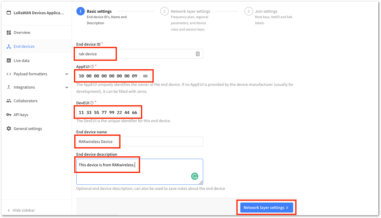 Figure 1: OTAA Device Information
- Next step is to set up Frequency plan, compatible Regional Parameter version, and LoRaWAN class supported. Then you can click Join settings.
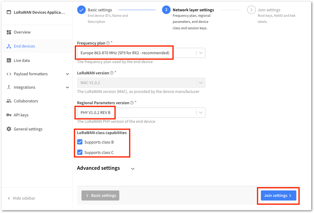 Figure 1: OTAA Configuration
- The last step in the registration of a new OTAA end-device is the configuration of the AppKey. To get the AppKey, you must click the generate button, then click Add end device to finish your new device registration.
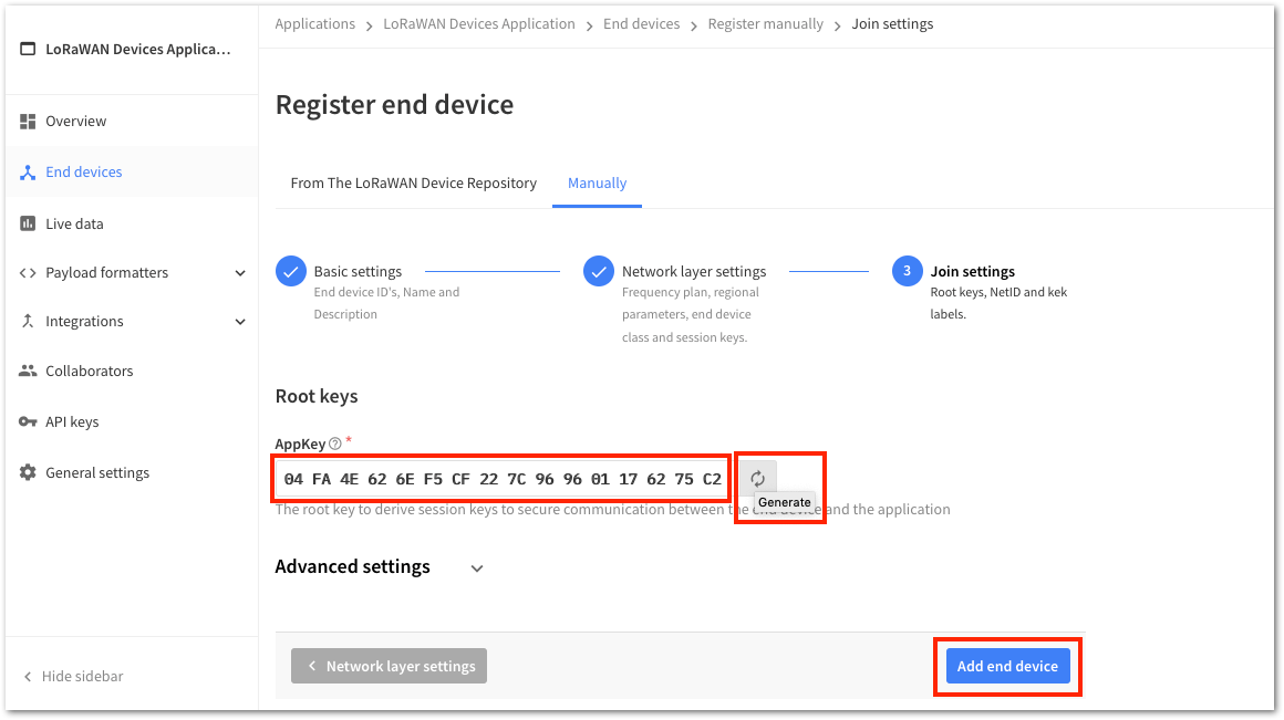 Figure 1: OTAA AppKey generation and device registration
You should now be able to see the device on The Things Stack console after you fully registered your device, as shown in Figure 27.
The AppEUI, DevEUI, and AppKey are the parameters you will need to activate your LoRaWAN end device via OTAA. The AppKey is hidden by default for security reasons, but you can easily show it by clicking the show button. You can also copy the parameters quickly using the copy button.
The three OTAA parameters on The Things Stack device console are MSB by default.
These parameters are always accessible on the device console page, as shown in Figure 27.
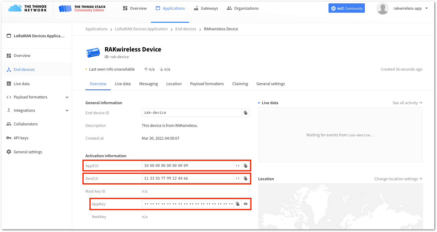 Figure 1: OTAA device successfully registered to The Things Stack
RAK4600 OTAA Configuration for The Things Stack
The RAK4600 module supports a series of AT commands to configure its internal parameters and control the functionalities of the module. To set up the RAK4600 module to join The Things Stack using OTAA, start by connecting the RAK4600 module to the computer (see Figure 1) and open the RAK Serial Port Tool. Wait for the communication to start. It is recommended to test the serial communication and verify the current configuration by sending either of these two AT commands:
at+set_config=device:restart
at+version
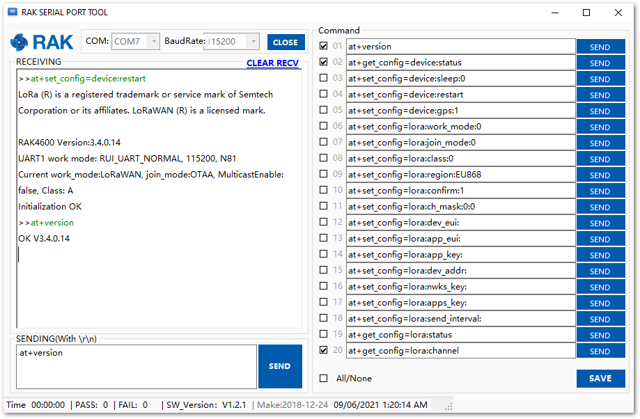 Figure 1: AT Command response
As an example, these are the list of the parameters you need to configure in RAK4600:
- LoRa join mode: OTAA
- LoRa class: Class A
- LoRa region: EU868
- Device EUI: 1133557799224466
- Application EUI: 1000000000000009
- Application Key: 04FA4E626EF5CF227C969601176275C2
- Set the LoRa join mode to OTAA.
at+set_config=lora:join_mode:0
- Set the LoRa class to Class A.
at+set_config=lora:class:0
- Set the frequency/region to EU868.
- Refer to the RAK4600 Datasheet for the list of supported frequencies.
at+set_config=lora:region:EU868
- Set the Device EUI.
at+set_config=lora:dev_eui:1133557799224466
- Set the Application EUI.
All zero value Application EUI at+set_config=lora:app_eui:0000000000000000 is not supported and will return error.
at+set_config=lora:app_eui:1000000000000009
- Set the Application Key.
at+set_config=lora:app_key:04FA4E626EF5CF227C969601176275C2
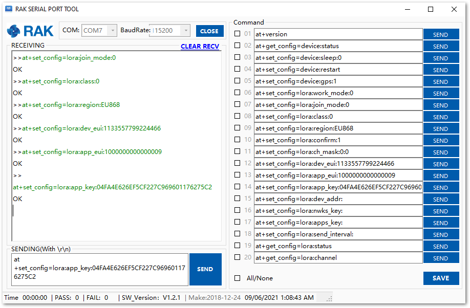 Figure 1: Configuring LoRa Parameters
After configuring all the parameters, you need to reset your RAK4600 Module to save the parameters.
- After resetting, join in OTAA mode.
at+join
After 5 or 6 seconds, if the request is successfully received by a LoRa gateway, then you should see the messages shown in Figure 30.
- Try to send a message from the RAK4600 module.
at+send=lora:2:1234567890
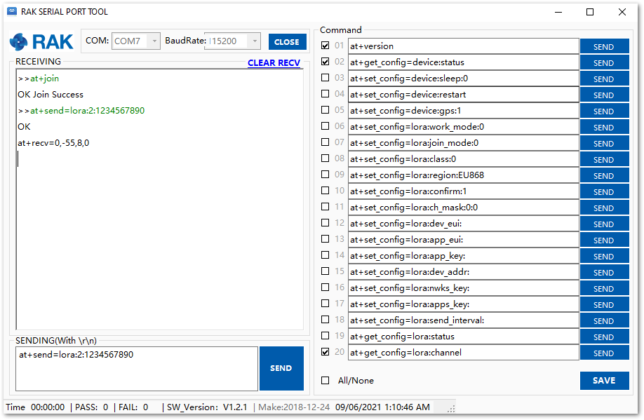 Figure 1: OTAA Test Sample Data Sent via RAK Serial Port Tool
You can see the data sent by the RAK4600 module on The Things Stack platform, as shown in Figure 31.
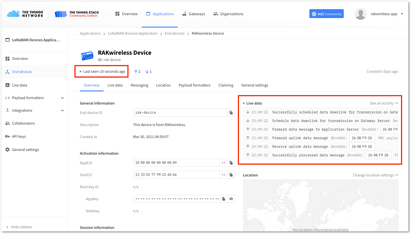 Figure 1: OTAA Test Sample Data Sent Viewed in The Things Stack
The Things Stack ABP Device Registration
- To register an ABP device, go to your application console and select the application where you want your device to be added, then click + Add end device, as shown in Figure 32.
 Figure 1: Add end device
- To register the module, you need to click first Manually then configure the activation method by selecting Activation by personalization (ABP), compatible LoRaWAN version, and click the Start button, as shown in Figure 33 and Figure 34.
 Figure 1: Add end device
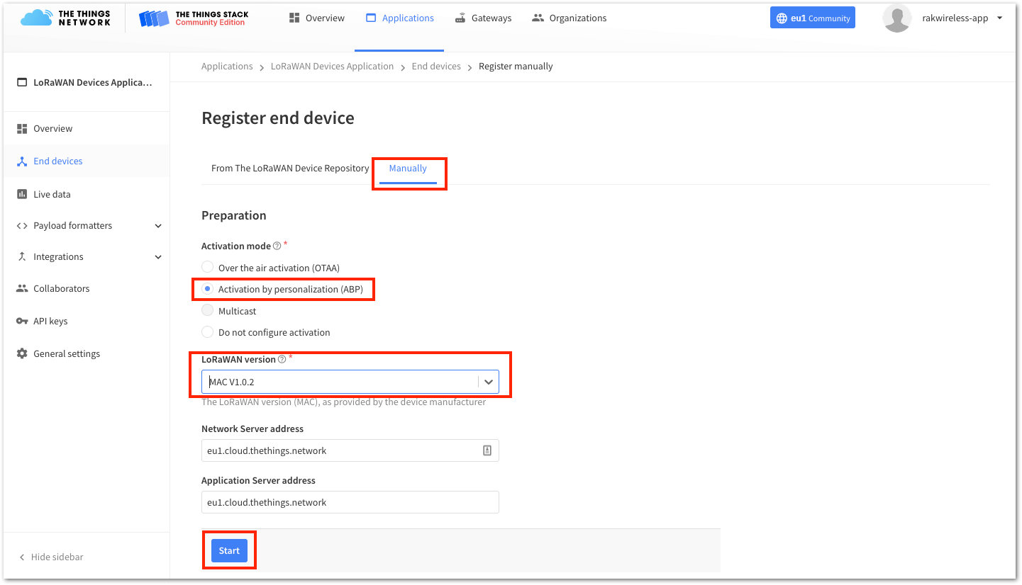 Figure 1: Manually register device to The Things Stack
- At this step, you need to put a unique End device ID and DevEUI, as shown in Figure 35. Check if your module has a DevEUI on sticker or QR that you can scan, then use this as the device unique DevEUI.
Optionally, you can add a more descriptive End device name and End device description about your device.
- After putting all the details, click Network layer settings to proceed to the next step.
It is advisable to use a meaningful End device ID, End device name, and End device description that will match your device purpose. The End device ID rak-device-abp is for illustration purposes only.
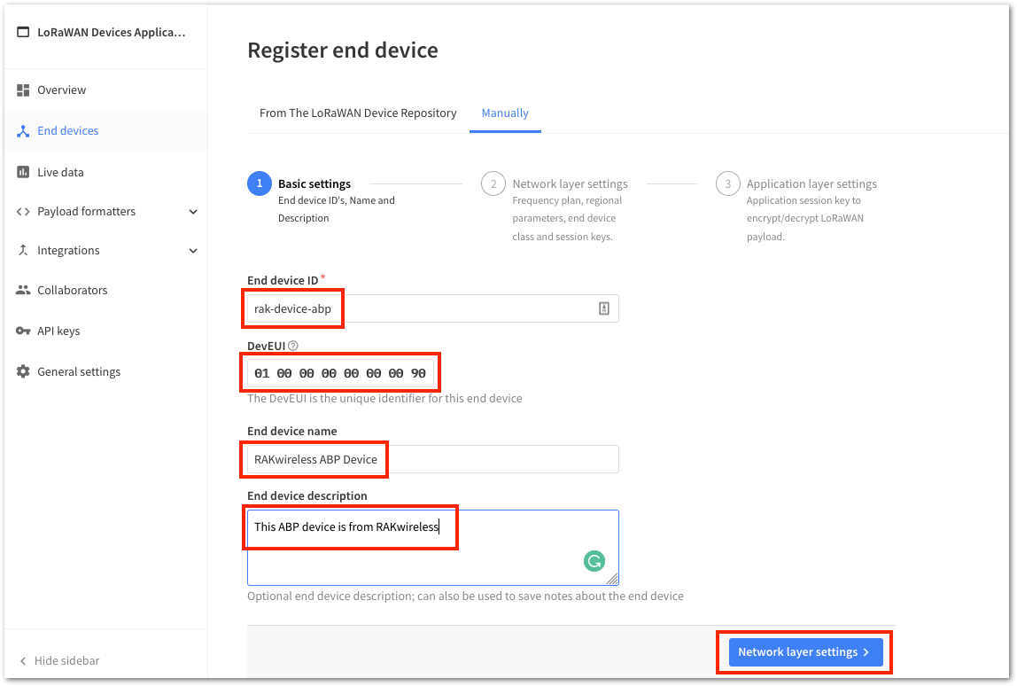 Figure 1: Device Information
- Next step is to set up Frequency plan, compatible Regional Parameter version, and LoRaWAN class supported. In an ABP device, you also need to generate Device Address and NwkSKey (Network Session Keys). Then, you can click Application layers settings.
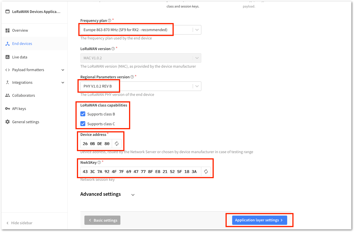 Figure 1: ABP Configuration in The Things Stack
- The last step in the registration of a new ABP end-device is the configuration of the AppSKey. To get the AppSKey, you must click the generate button, then click Add end device to finish your new device registration.
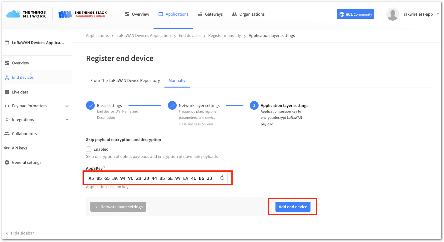 Figure 1: ABP Configuration in The Things Stack
You should now be able to see the device on The Things Stack console after you fully registered your device, as shown in Figure 38.
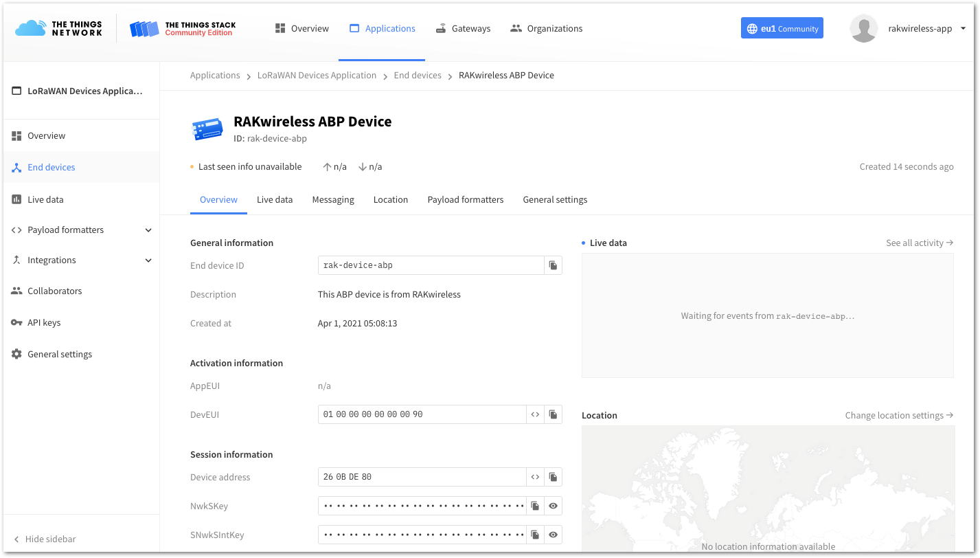 Figure 1: RAK4600 registered at The Things Stack
RAK4600 ABP Configuration for The Things Stack
To set up the RAK4600 module to join The Things Stack using ABP, start by connecting the RAK4600 module to the computer (see Figure 1) and open the RAK Serial Port Tool. It is recommended to test the serial communication by sending either of these two AT commands:
at+set_config=device:restart
at+version
 Figure 1: AT Command response
As an example, these are the list of the parameters you need to configure in RAK4600:
- LoRa join mode: ABP
- LoRa class: Class A
- LoRa region: EU868
- Device address: 260BDE80
- Network Session Key: 433C7A924F7F6947778FE821525F183A
- Application Session Key: A585653A949C2B2D44B55E99E94CB533
- Set the LoRa join mode to ABP.
at+set_config=lora:join_mode:1
- Set the LoRa class to Class A.
at+set_config=lora:class:0
- Set the frequency/region to EU868.
- Refer to the RAK4600 Datasheet for the list of supported frequencies.
at+set_config=lora:region:EU868
- Set the Device Address.
at+set_config=lora:dev_addr:260BDE80
- Set the LoRa Network Session Key.
at+set_config=lora:nwks_key:433C7A924F7F6947778FE821525F183A
- Set the LoRa Application Session Key.
at+set_config=lora:apps_key:A585653A949C2B2D44B55E99E94CB533
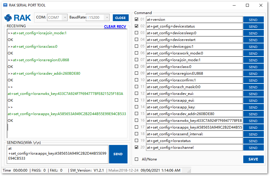 Figure 1: AT Command for ABP LoRa parameters via RAK Serial Port Tool
After configuring all the parameters, you need to reset the RAK4600 Module to save the parameters.
- After resetting, join in ABP mode.
at+join
By using the ABP mode in LoRaWAN, it doesn’t require to join a network before sending a LoRaWAN package. But to keep the consistency of internal states of the firmware of the RAK4600 module, it is still required to send the at+join command in the ABP mode. This time, the firmware should reply almost immediately with an “OK”.
- Try to send data from the RAK4600 to The Things Network in ABP mode.
at+send=lora:2:1234567890
 Figure 1: ABP Test Sample Data Sent via RAK Serial Port Tool
You can see the data sent by the RAK4600 module on The Things Stack device console Live data section and the Last seen info should be a few seconds ago.
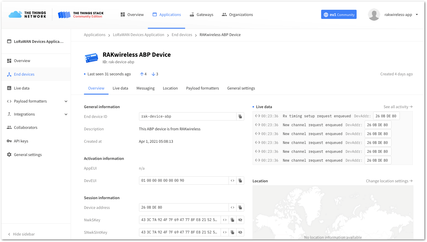 Figure 1: OTAA Test Sample Data Sent Viewed in The Things Stack
Connecting with ChirpStack
This section shows how to connect the RAK4600 to the ChirpStack platform. As described in the ChirpStack website:
“The ChirpStack open-source LoRaWAN Network Server stack provides open-source components for LoRaWAN networks. Together they form a ready-to-use solution including a user-friendly web interface for device management and APIs for integration. The modular architecture makes it possible to integrate within existing infrastructures. All components are licensed under the MIT license and can be used for commercial purposes.”
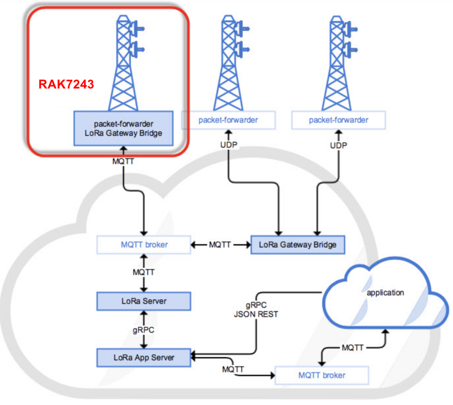 Figure 1: RAK4600 in the context of the ChirpStack platform
The architecture of the ChirpStack platform is shown in Figure 43. Similar to the case of TTN, the RAK4600 is located in the periphery and will transmit the data to the backend servers through a LoRa gateway. More information about this architecture can be found at https://www.chirpstack.io/.
- In this section, it is assumed that you are using a RAK LoRa gateway, such as RAK7243. The gateway must be configured and registered previously to ChirpStack deployment. More information can be found in the Connect the Gateway with Chirpstack section.
The frequency band used in this example is EU868 which is supported by the high-frequency version of RAK4600.
-
These are the steps needed to send data to the ChirpStack platform from a RAK4600 module:
- Create a new Application
- Register a new device on the platform
- Configure the Join Mode:
- OTAA mode on the platform
- OTAA mode on the RAK4600
- ABP mode on the platform
- ABP mode on the RAK4600
- Send data from the RAK4600 and receive it at the platform
The following section gives the details of each of these aforementioned steps. As usual, you must choose to use either ABP or OTAA mode to register the device to the network server.
Create a new Application
- Go to the Application section, then click on the “+ CREATE” button.
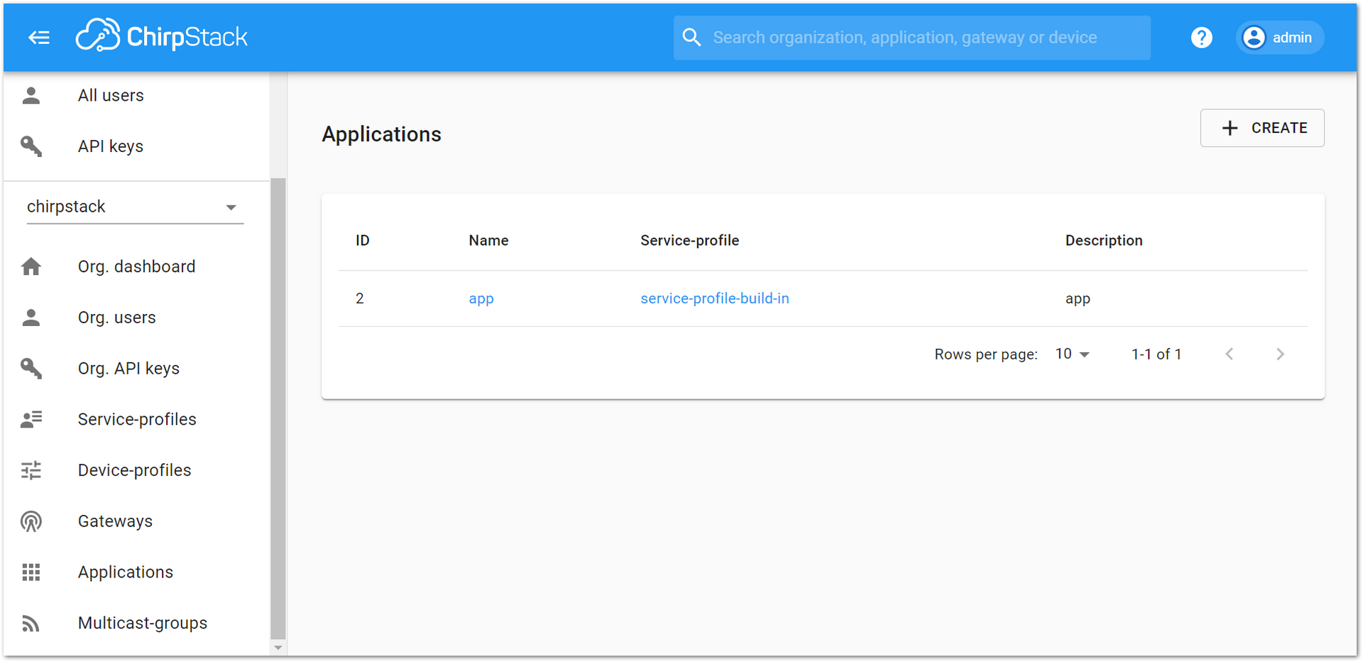 Figure 1: Application section of the RAK’s ChirpStack LoRaServer
- ChirpStack LoraServer supports multiple system configurations, with only one by default. By default, a new Application should be created, although it is possible to reuse the existing ones. For this setup, create a new Application by clicking on the "CREATE APPLICATION" button.
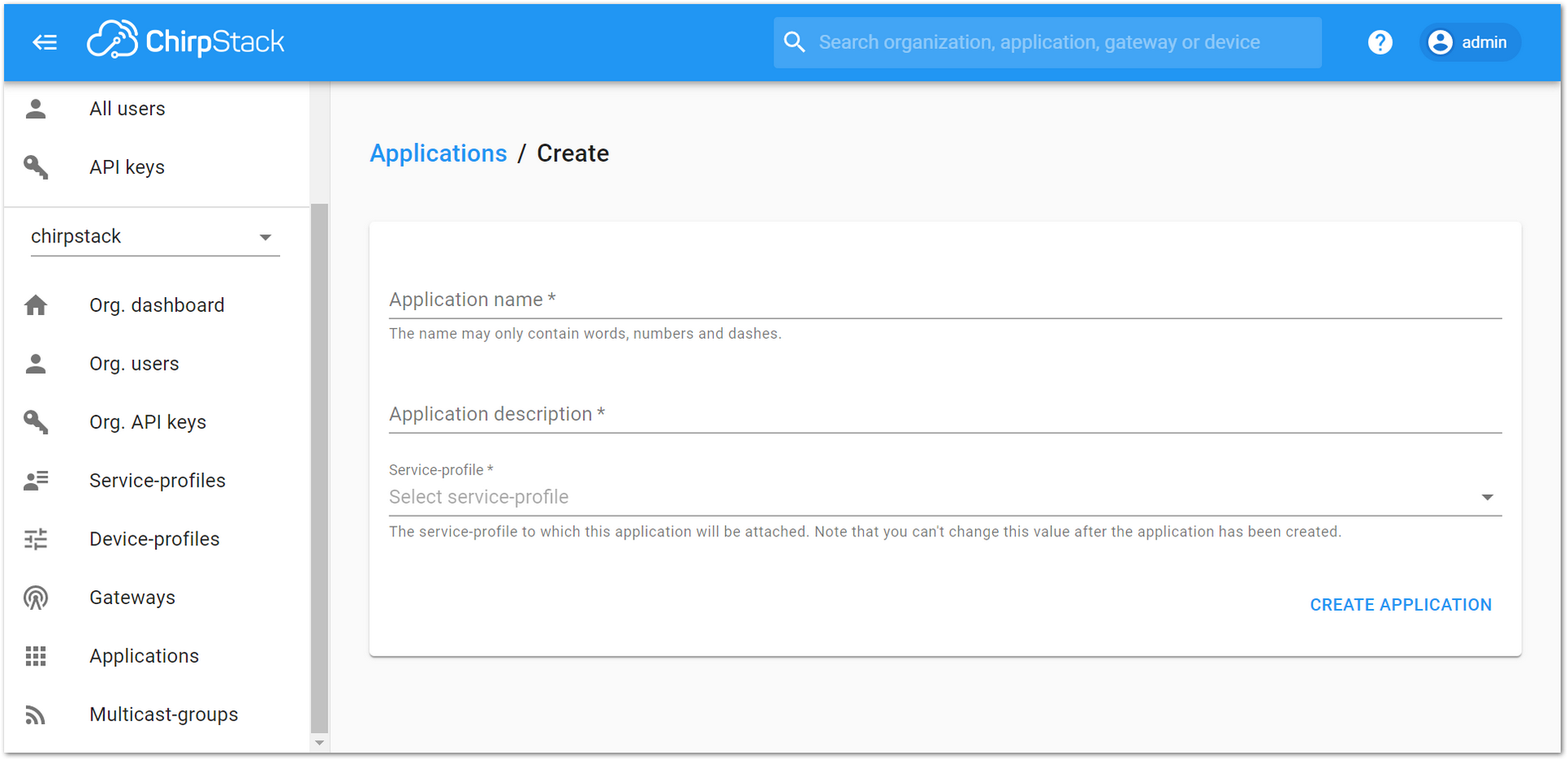 Figure 1: Creating a new Application on the RAK’s ChirpStack LoRaServer
- Create an Application named “rak_node_test”. Fill in the required parameters, as shown in Figure 46. To finish, click on the CREATE APPLICATION button.
- Application Name: rak_node_test
- Application Description: test
- Service profile: field is to select the system profile.
The Application Description field is just a descriptive text.
“CREATE APPLICATION”.
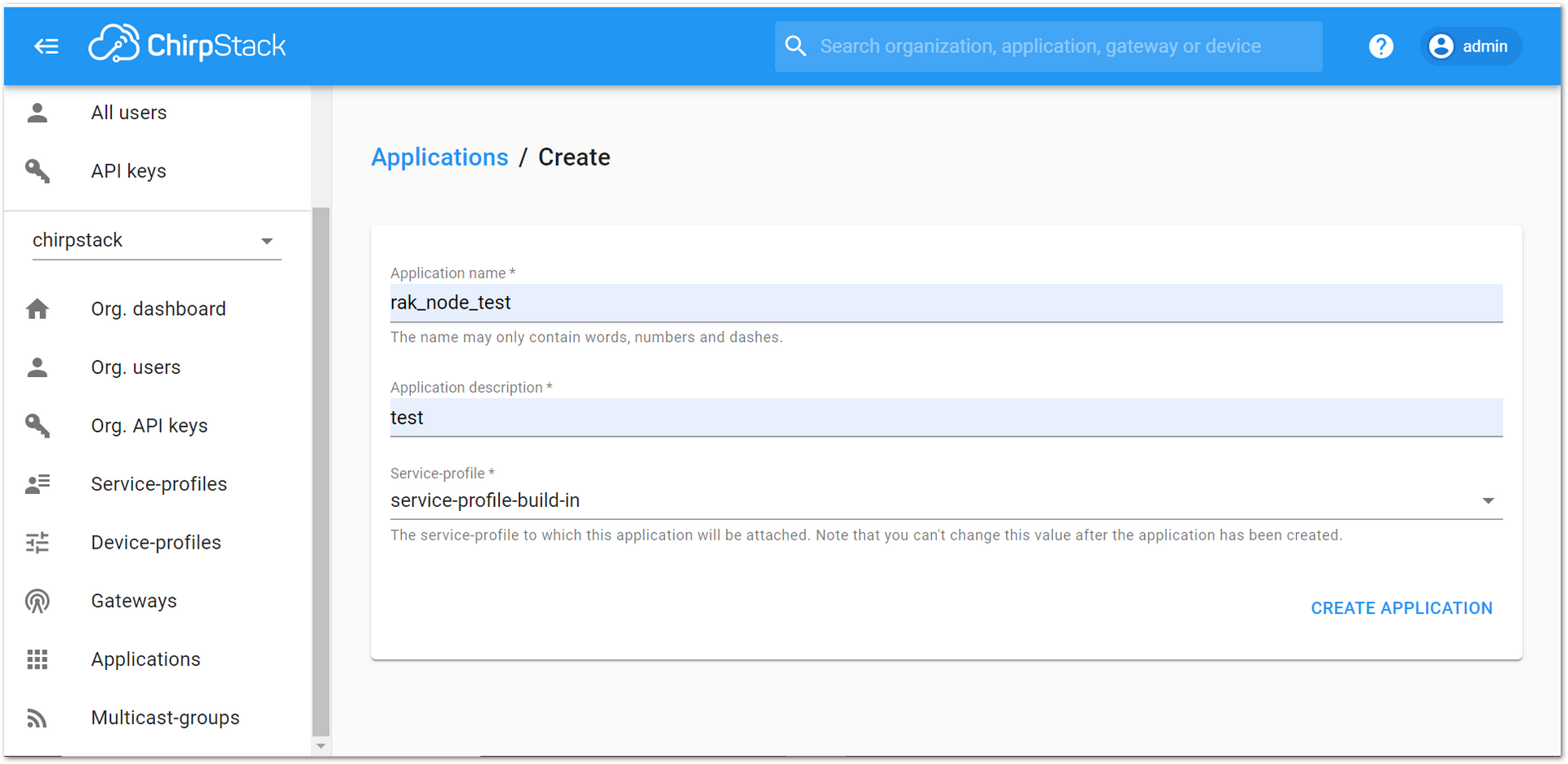 Figure 1: Filling parameters of an Application on the RAK’s ChirpStack LoRaServer
- Click on the Application ��“rak_node_test” created in the previous step.
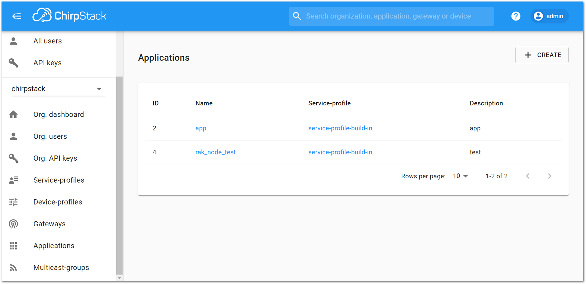 Figure 1: List of applications created on the RAK’s ChirpStack LoRaServer
- Select the “DEVICES” tab, as shown in Figure 48.
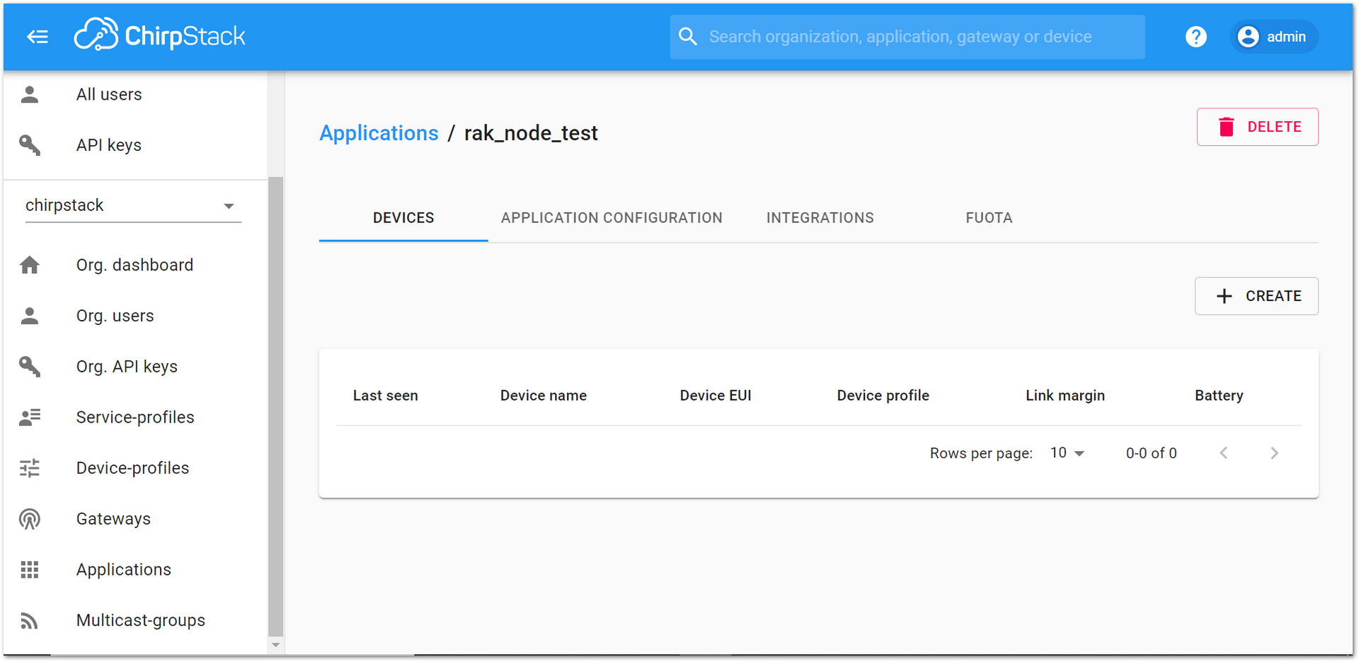 Figure 1: Device tab of an Application on the RAK’s ChirpStack LoRaServer
- Inside of the “DEVICES” tab, create a new device (LoRa node) by clicking on the “+ CREATE” button.
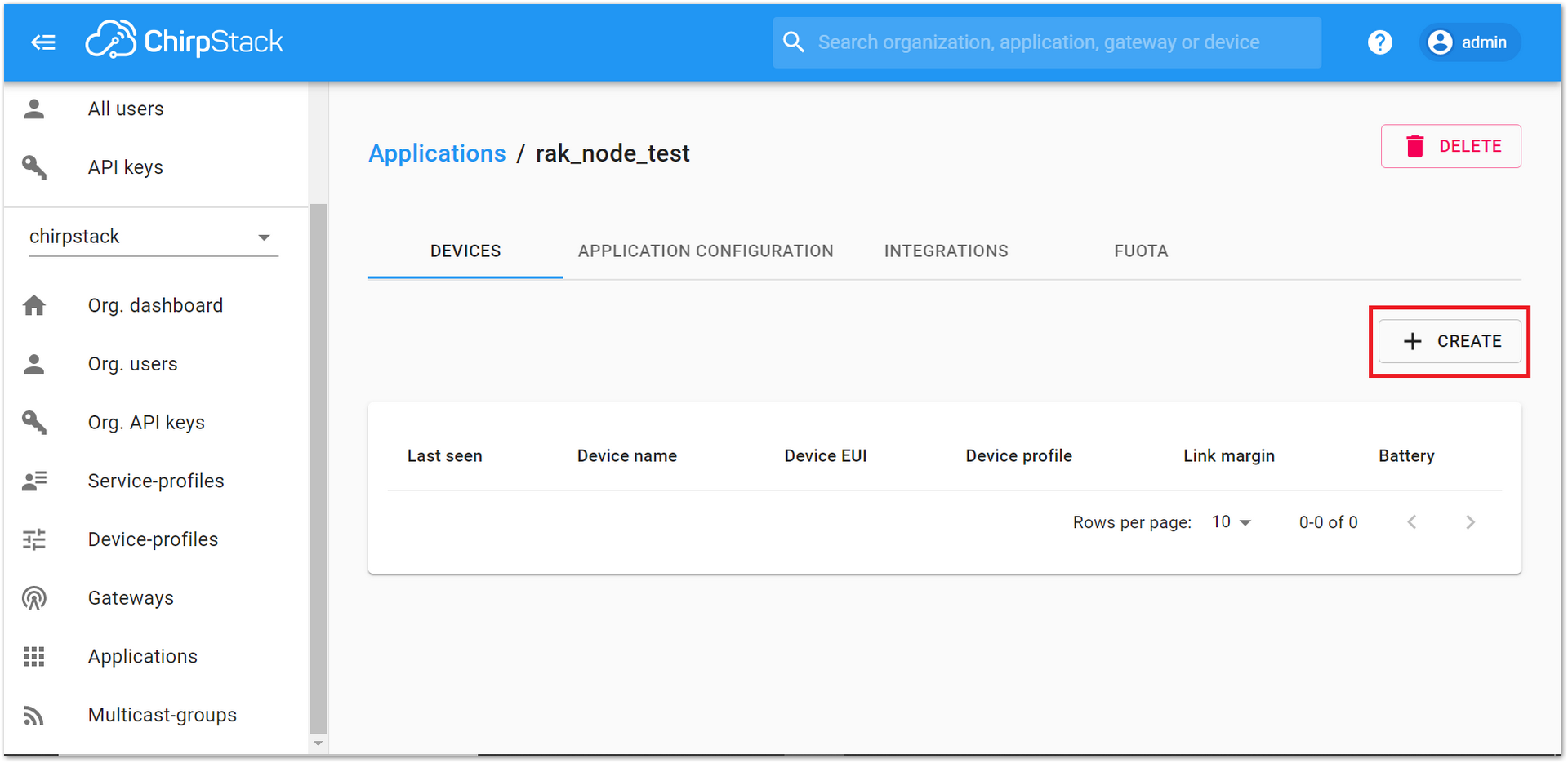 Figure 1: Add a new device at DEVICES tab of an Application on the RAK’s ChirpStack LoRaServer
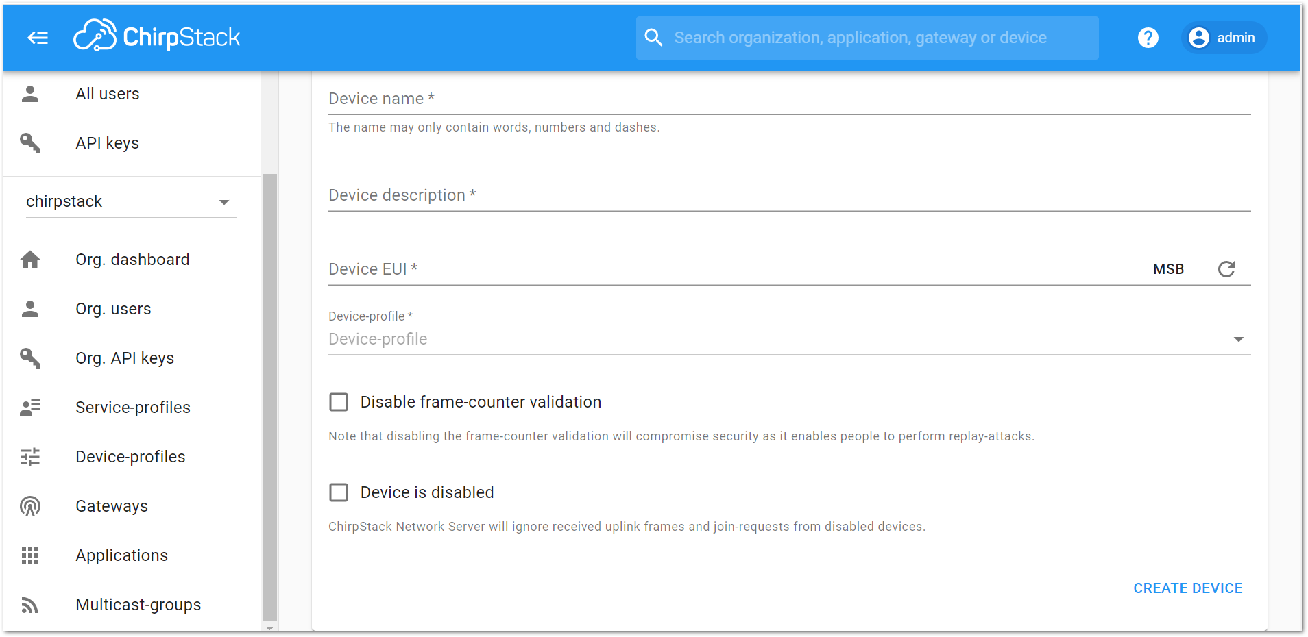 Figure 1: New device registration form on the RAK’s ChirpStack LoRaServer
- Fill the parameters requested as appears in Figure 50.
- Device name and Device description: These are just descriptive texts.
- Device EUI: This interface allows you to generate a Device EUI automatically by clicking the icon highlighted in red in Figure 51. You can also add a specific Device EUI directly in the form.
- Device-profile: To join in OTAA mode, select “device_profile_otaa” or “device_profile_abp” to join in ABP mode.
ChirpStack doesn’t support AS923 in ABP mode.
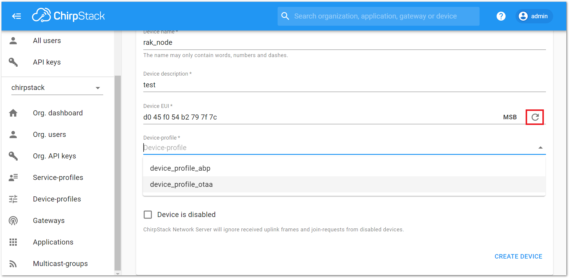 Figure 1: Generate a new Device EUI in the device registration form
LoRaWAN Join Mode
The LoRaWAN specification defines that to join in a LoRaWAN network, each end-device has to be personalized and activated. Activation can be done either via Over-The-Air-Activation (OTAA) or via Activation-By-Personalization (ABP). In OTAA, the end-device previously personalized is activated when deployed or reset. In ABP, personalization and activation are done as a single step.
OTAA Mode
Configure the OTAA Mode on the Platform
- If you have selected “device_profile_otaa”, then after the device is created, an Application Key must be also created for this device.
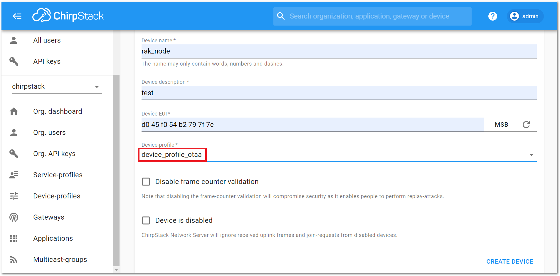 Figure 1: Choosing OTAA mode in the device registration form
- A previously created Application Key can be entered here, or a new one can be generated automatically by clicking on the icon highlighted in red.
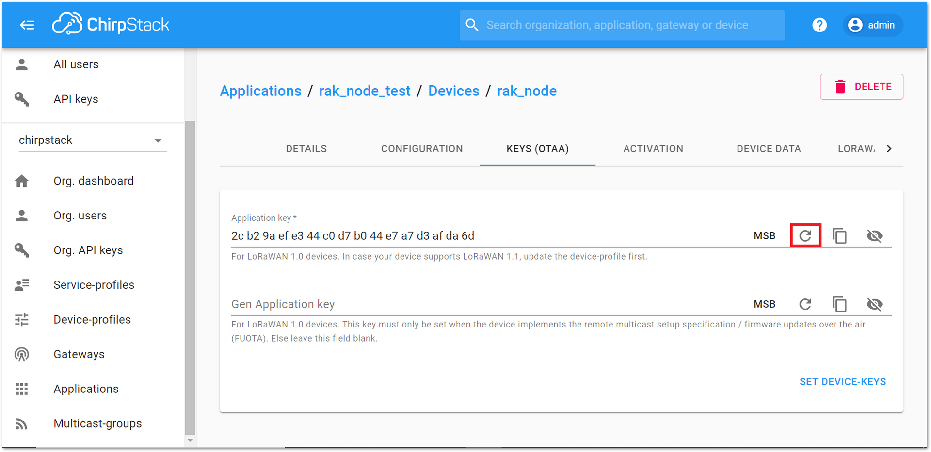 Figure 1: Application Key for the OTAA mode in the device registration form
- Once the Application Key is added to the form, the process can be finalized by clicking on the “SET DEVICE-KEYS” button.
- As shown in Figure 54, a new device should be listed in the “DEVICES” tab. The most important parameters, such as the Device EUI are shown in the summary.
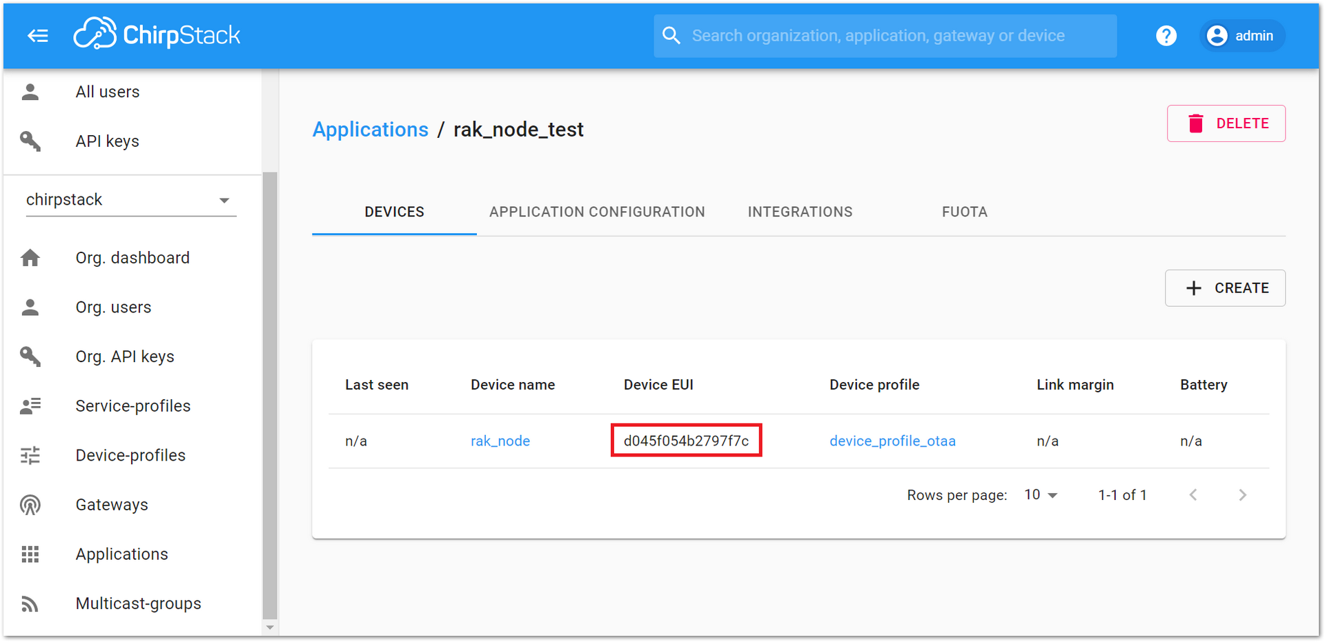 Figure 1: New crated device listed in the DEVICES tab
- To end the process, it is a good practice to review that the “Application Key” is properly associated with this device. The “Application Key” can be verified in the “KEYS(OTAA)” tab.
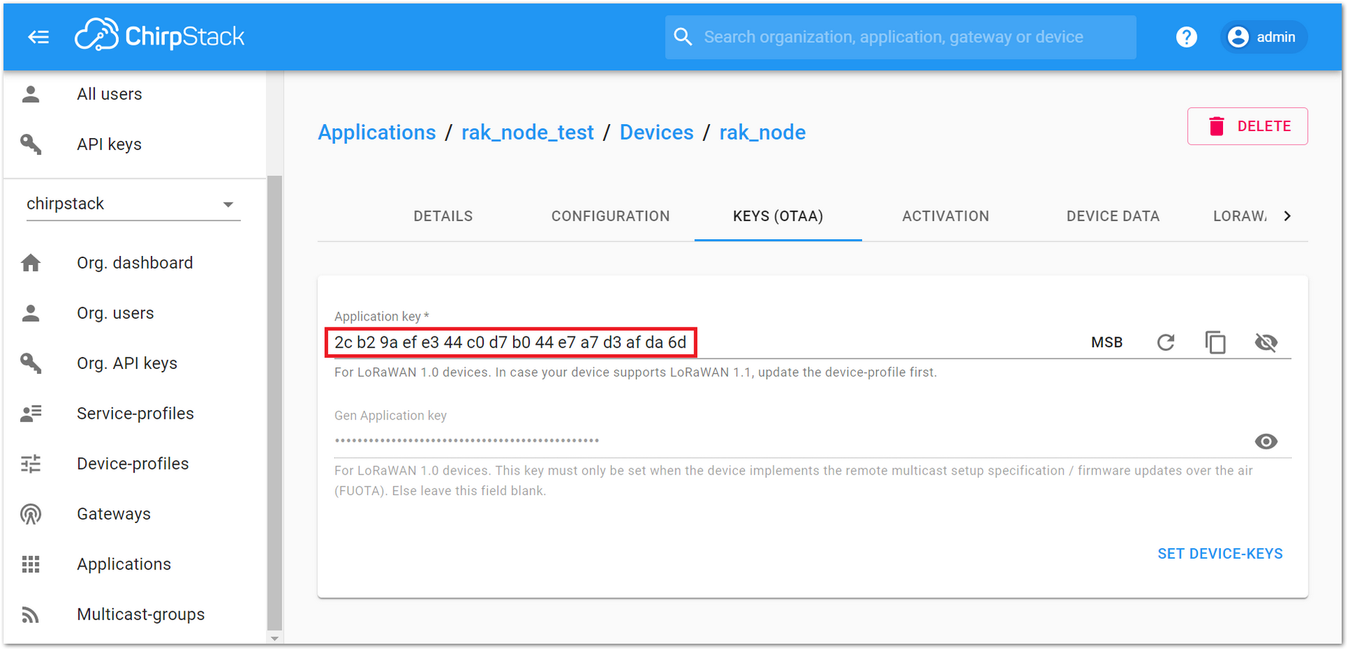 Figure 1: Application Key associated to the new device
Standard OTAA mode requires the Device EUI, Application Key, and the Application EUI, but in the ChirpStack’s implementation, only Device EUI and the Application Key are mandatory. The Application EUI is not required and is not recorded in the Application tab. Nevertheless, the Application EUI is a mandatory parameter in the RAK4600 module firmware. To resolve this mismatch, you can reuse the Device EUI as the Application EUI during the configuration on the side of the node.
Configure the OTAA mode on the RAK4600
RAK4600 complies with the LoRaWAN 1.0.2 specification. By default, the LoRa join mode is OTAA and the LoRa Class is Class A.
To set up the RAK4600 to join ChirpStack using OTAA, start by connecting the RAK4600 to the computer as shown in section Interfacing with RAK4600. Open the RAK Serial Port Tool and wait for the communication to start. It is recommended to test the serial communication by sending an AT command as:
at+get_config=lora:status
or
at+version
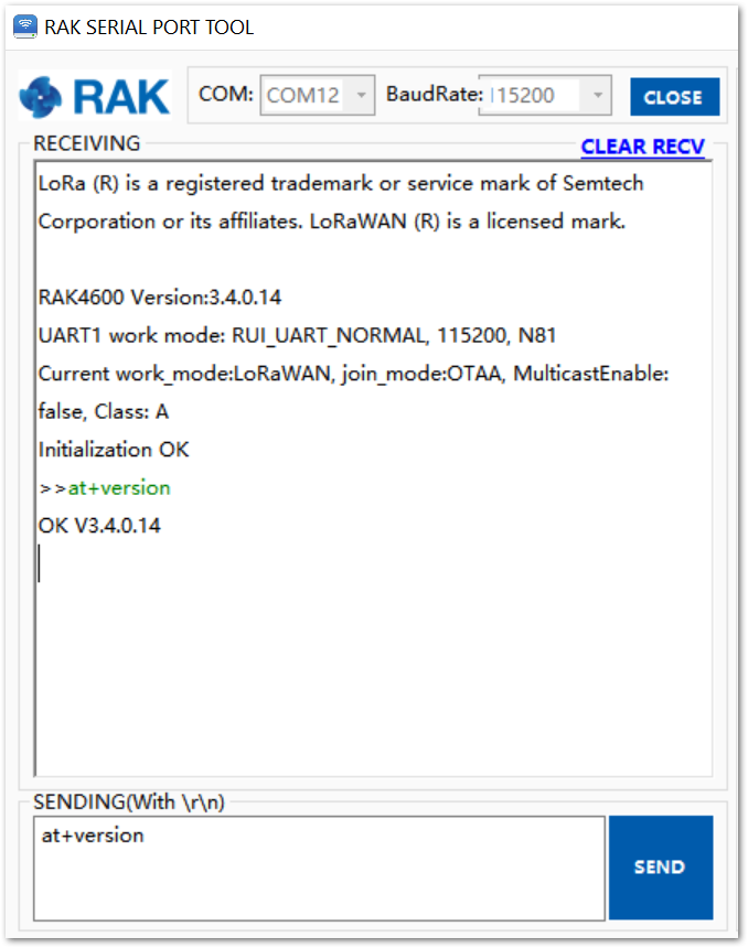 Figure 1: RAK Serial Port Tool connected to a RAK4600
As an example, the following parameters will be configured in RAK4600:
- LoRa join mode: OTAA
- LoRa class: Class A
- LoRa region: EU868
- Device EUI: d045f054b2797f7c (from ChirpStack registration)
- Application EUI: d045f054b2797f7c (from ChirpStack registration)
- Application Key: 2cb29aefe344c0d7b044e7a7d3afda6d (from ChirpStack registration)
- Set the LoRa join mode to OTAA.
at+set_config=lora:join_mode:0
- Set the LoRa Class to Class A.
at+set_config=lora:class:0
- Set the frequency/region.
- Refer to the RAK4600 Datasheet for the list of supported frequencies.
For the Europe region, type the command:
at+set_config=lora:region:EU868
Remember that the device frequency shall be in the same frequency band as the gateway.
- Set the Device EUI.
Get the Device EUI number from the ChirpStack register.
at+set_config=lora:dev_eui:d045f054b2797f7c
- Set the Application EUI.
Get the Application EUI number from the ChirpStack register.
at+set_config=lora:app_eui:d045f054b2797f7c
Remember, the Application EUI parameter is not required in the ChirpStack platform; therefore, it is possible to use the same id as the Device EUI. Otherwise, the firmware will complain.
- Set the Application Key.
Get the Application Key from the TTN register.
at+set_config=lora:app_key:2cb29aefe344c0d7b044e7a7d3afda6d
- Save RAK4600 parameters.
Reset the RAK4600 to save the parameters.
Figure 57 summarizes the set of commands sent over the console for setting the OTAA mode on the RAK4600
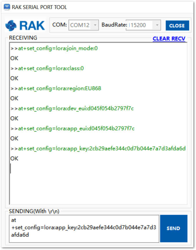 Figure 1: RAK4600 LoRa parameters configuration over the Serial Port Tool
- Command the RAK4600 to join in OTAA mode
at+join
- After 5 or 6 seconds, if the request is successfully received by a LoRa gateway, then the “OK Join Success” message will be shown.
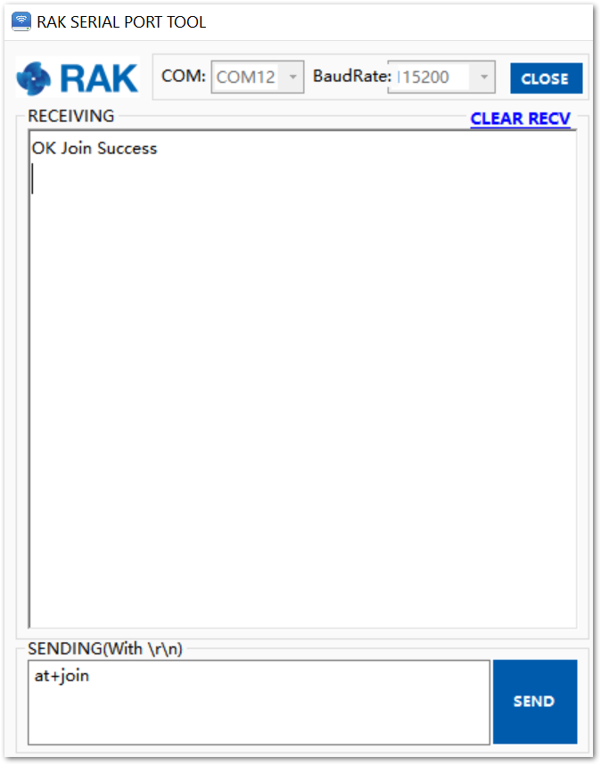 Figure 1: RAK Serial Port Tool, join the network
- The JoinRequest and JoinAccept messages are also displayed on the ChirpStack platform, specifically in the LORAWAN FRAMES section.
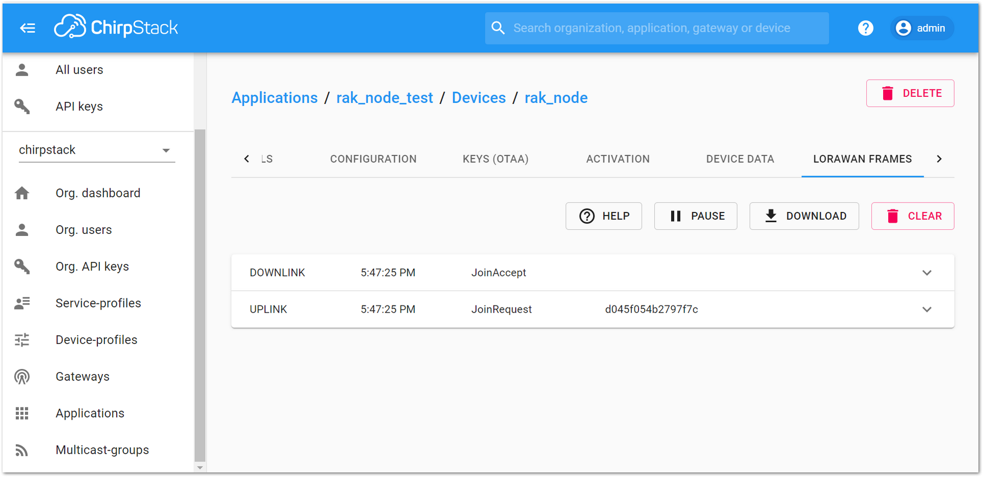 Figure 1: ChirpStack Console, checking LoRaWAN join request
- Send data from RAK4600 to ChirpStack
For example, to send the string 1234567890 over LoRa port 2, type the command:
at+send=lora:2:1234567890
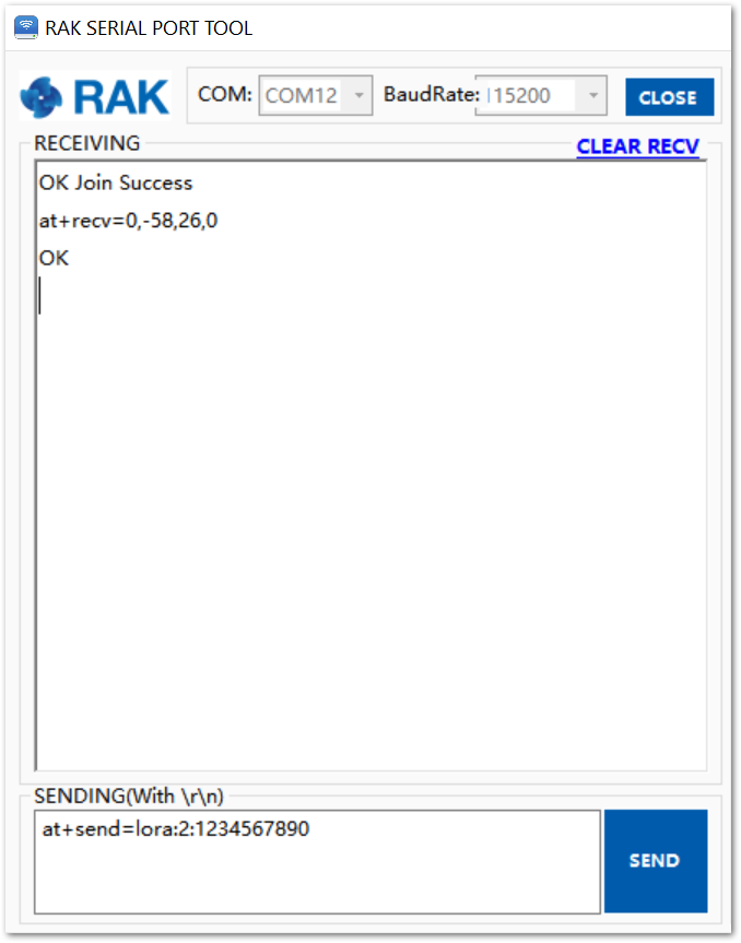 Figure 1: RAK Serial Port Tool, send a LoRaWAN message
On the ChirpStack platform, the messages shall appear in the “LORAWAN FRAMES” tab, as shown in Figure 61.
By convention, messages sent from nodes to the gateway are considered as UPLINK, while messages sent by the gateway to nodes are considered as a DOWNLINK.
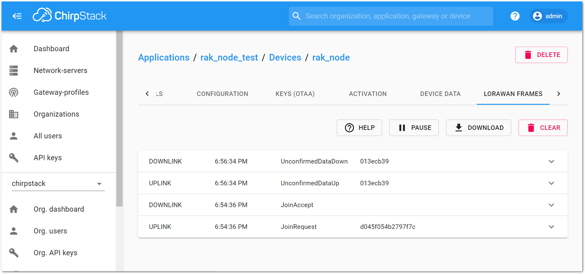 Figure 1: ChirpStack Console, checking LoRaWAN messages received
ABP Mode
Configure the ABP Mode on the Platform
During the registration of a new device, if “device_profile_abp” is selected, then the ChirpStack platform will assume that this device will join the LoRaWAN network using the ABP mode.
- Fill in the parameters requested, as appears in Figure 62:
- Device name and Device description: These are just descriptive texts.
- Device EUI: You can also add a specific Device EUI directly in the form.
- Once these parameters are filled, click on the “CREATE DEVICE” button.
Check Disable counting frame verification to prevent the node-side frame counting from starting from zero after the node is powered on during the test. The server cannot synchronize the node-side counting, causing the transmission to fail.
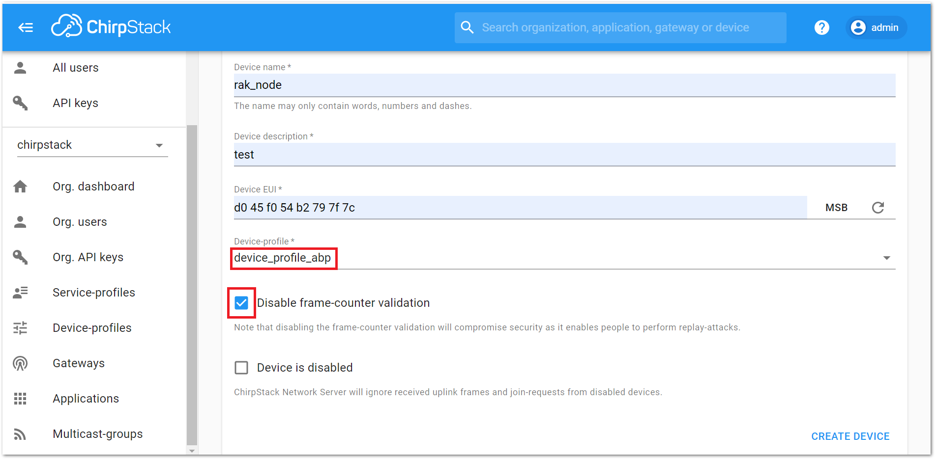 Figure 1: ChirpStack Console, configuring a device in ABP mode
- After selecting the ABP mode, the following parameters appear in the ACTIVATION tab below:
- Device address
- Network Session Key
- Application Session Key
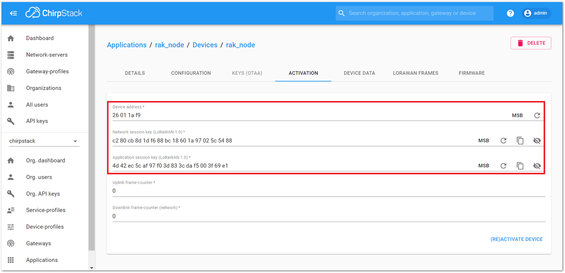 Figure 1: ChirpStack Console, parameters required for the ABP mode
- The parameters can be generated as random numbers by the platform or can be set with user values. Once these parameters are filled properly, the process is completed by clicking on the “(RE)ACTIVATE DEVICE” button.
Configure the ABP mode on the RAK4600
RAK4600 complies with the LoRaWAN 1.0.2 specification. The RAK4600 LoRa join mode is OTAA by default and the LoRa Class is Class A.
To set up the RAK4600 module to join ChirpStack using ABP, start by connecting the RAK4600 to the computer as shown in section Interfacing with RAK4600. Open the RAK Serial Port Tool, wait for the communication to start. It is recommended to test the serial communication by sending an AT command as:
at+get_config=lora:status
or
at+version
 Figure 1: RAK Serial Port Tool connected to a RAK4600
As an example, the following parameters will be configured in RAK4600:
- LoRa join mode: ABP
- LoRa class: Class A
- LoRa region: EU868
- Device address: 26011af9 (from ChirpStack registration)
- Network Session Key: c280cb8d1df688bc18601a97025c5488 (from ChirpStack registration)
- Application Session Key: 4d42ec5caf97f03d833cdaf5003f69e1 (from ChirpStack registration)
- Set the LoRa join mode to ABP.
at+set_config=lora:join_mode:1
- Set the LoRa Class to Class A.
at+set_config=lora:class:0
- Set the frequency/region.
- Refer to the RAK4600 Datasheet for the list of supported frequencies.
For the Europe region, type the command:
at+set_config=lora:region:EU868
- Set the Device Address.
Get the Device Address from ChirpStack registration.
at+set_config=lora:dev_addr:26011af9
- Set the Network Session Key.
Get the Network Session Key from the ChirpStack registration.
at+set_config=lora:nwks_key:c280cb8d1df688bc18601a97025c5488
- Set the Application Key.
Get the Application Key from the ChirpStack registration.
at+set_config=lora:apps_key: 4d42ec5caf97f03d833cdaf5003f69e1
- Save RAK4600 parameters.
Reset the RAK4600 to save the parameters.
Figure 55 summarizes the set of commands sent over the console for setting the ABP mode on the RAK4600.
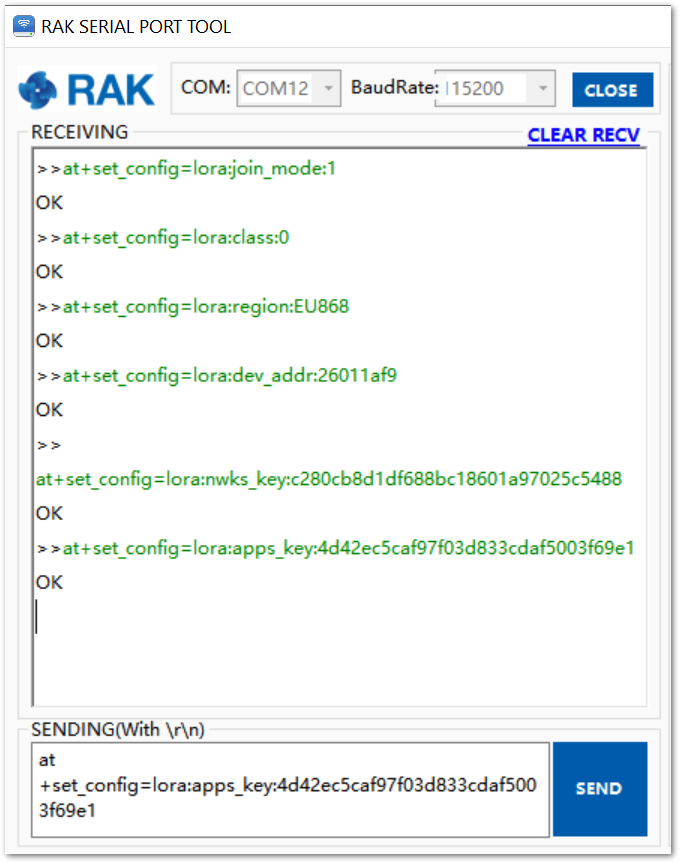 Figure 1: RAK4600 LoRa parameters configuration over the Serial Port Tool
- Command the RAK4600 to join in ABP mode.
at+join
Almost immediately after sending the command, the “OK Join Success” should be replied to in the console, as shown in Figure 66.
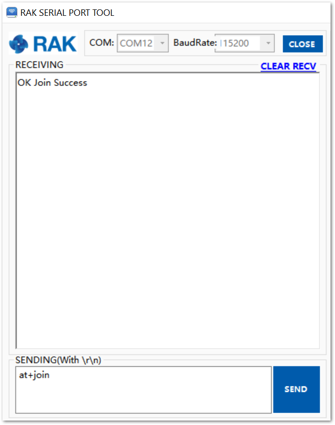 Figure 1: RAK Serial Port Tool join LoRaWAN in ABP mode.
The ABP mode in LoRaWAN doesn’t require to join a network before sending a LoRaWAN package. But, to keep the consistency of internal states of the firmware of the RAK4600, it is still required to send the at+join command in the ABP mode.
- Send data from RAK4600 to ChirpStack.
For example, to send the string 1234567890 over LoRa port 2, type the command:
at+send=lora:2:1234567890
The console will feedback with an “OK” message.
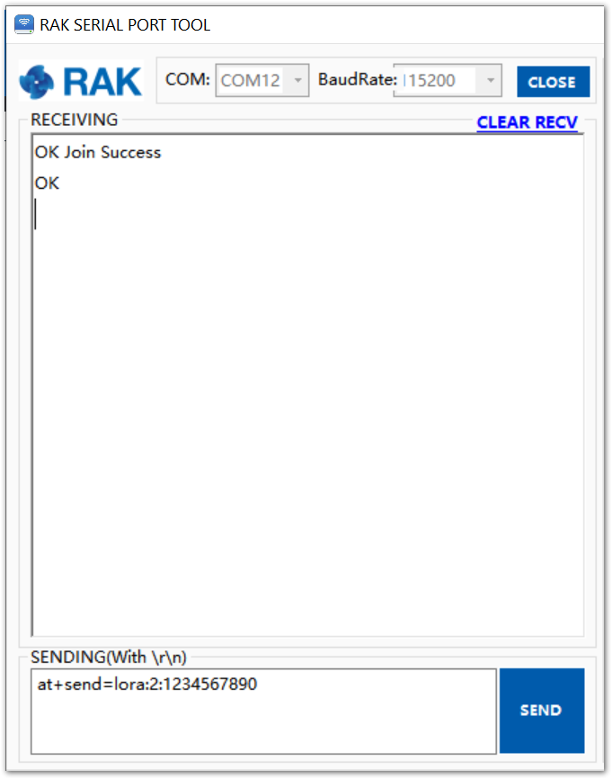 Figure 1: RAK Serial Port Tool ABP message sent
 The sent data shall be displayed on the ChirpStack console on the LORAWAN FRAMES tab.
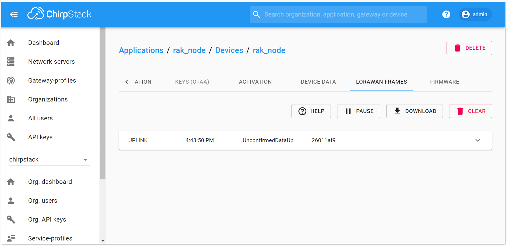 Figure 1: ChirpStack console UPLINK LoRaWAN frame in ABP mode.
LoRa P2P Mode
This section will show how to set and link two RAK4600 units to work in LoRa P2P mode.
-
The two RAK4600 units shall be set to operate at the same frequency, for this demonstration: EU868.
-
As shown in the previous sections, the setup of the RAK4600 units is done by connecting them with a general-purpose computer through the UART port, as shown in section Interfacing with RAK4600. The setup of each RAK4600 can be done separately, but testing the LoRa P2P mode will require having both units connected simultaneously to a UART port (This could be one computer with two (2) ports or two (2) computers with one UART port each).
-
To set the RAK4600 to work in LoRa P2P mode, open the RAK Serial port tool and send the command, as shown in Figure 69.
at+set_config=lora:work_mode:1
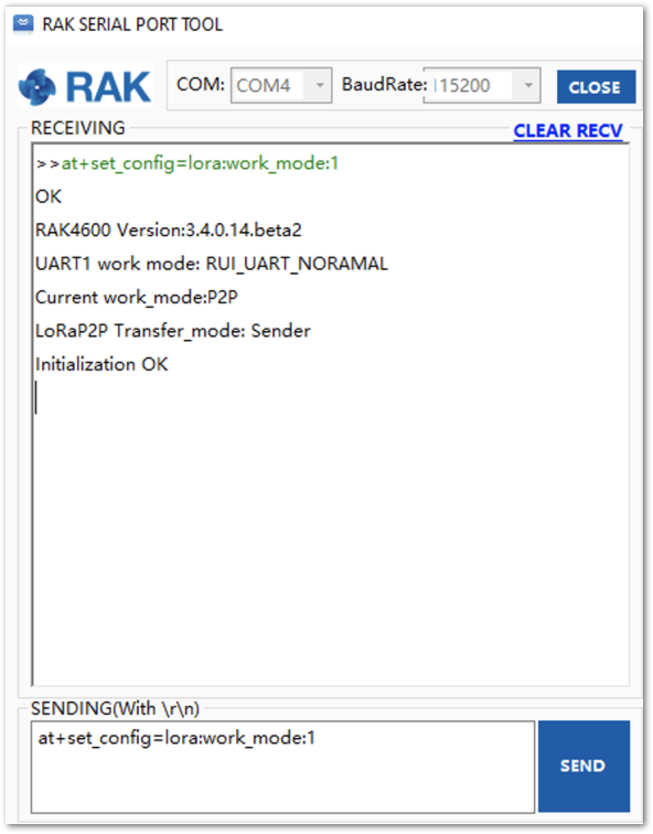 Figure 1: RAK4600 setting to LoRa P2P mode
- Configure the LoRa P2P parameters for both units. The command for setting the parameters has the following format:
at+set_config=lorap2p:XXX:Y:Z:A:B:C
-
Based on the AT Commands for RAK4600, the parameters are:
- XXX: Frequency in Hz.
- Y: Spreading factor, [6, 7, 8, 9, 10, 11, 12].
- Z: Bandwidth, [0:125 kHz, 1:250 kHz, 2:500 kHz]
- A: Coding Rate, [1: 4/5, 2: 4/6, 3: 4/7, 4: 4/8]
- B: Preamble Length, 5~65535.
- C: Power in dBm, 5~20.
For this example, the LoRa parameters are:
- Link frequency: 869525000 Hz
- Spreading factor:7
- Bandwidth: 125 kHz
- Coding Rate:4/5
- Preamble Length: 5
- Power: 5 dBm
- The set parameters are translated into the following RAK4600 AT command that is sent to both units, as shown in Figure 70.
at+set_config=lorap2p:869525000:7:0:1:5:5
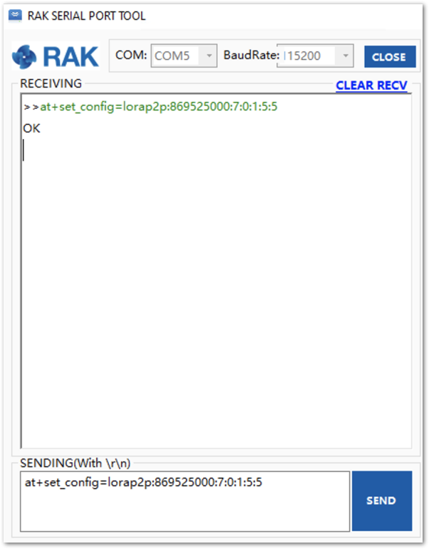 Figure 1: Setting both RAK4600 units with the LoRa P2P parameters
- Next, set the transmission mode of the RAK4600. In this example, Unit 1 is set to sender mode, and Unit 2 is set to receiver mode by AT command.
- Unit 1 (Sender):
at+set_config=lorap2p:transfer_mode:2
- Unit 2 (Receiver):
at+set_config=lorap2p:transfer_mode:1
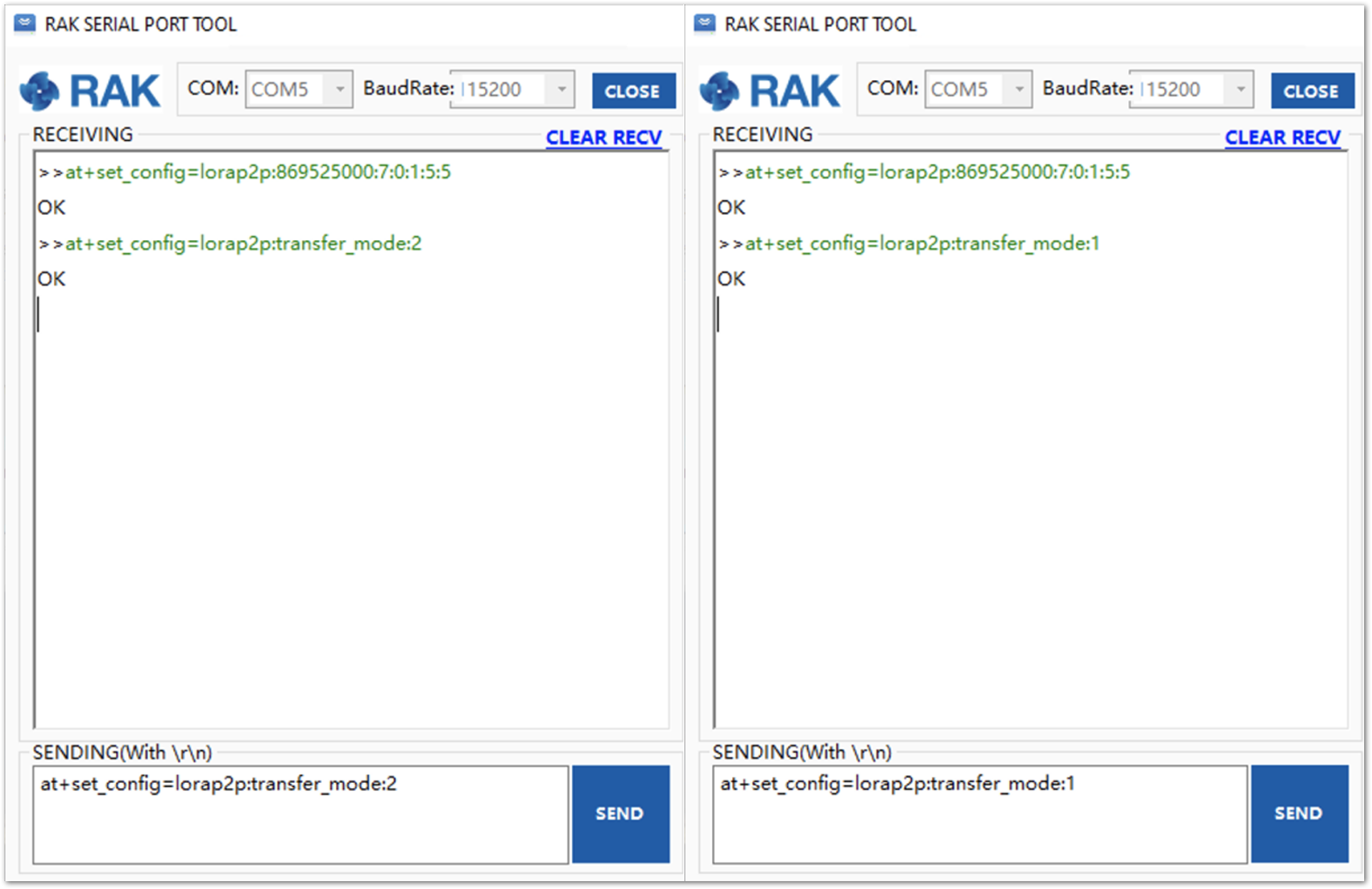 Figure 1: Set the module in the sender (left) and the receiver (right) mode
- Now, to send a message, the string “123456890” from Unit1 to Unit2. Type the command on Unit 1:
at+send=lorap2p:1234567890
- The message will be automatically received by Unit 2.
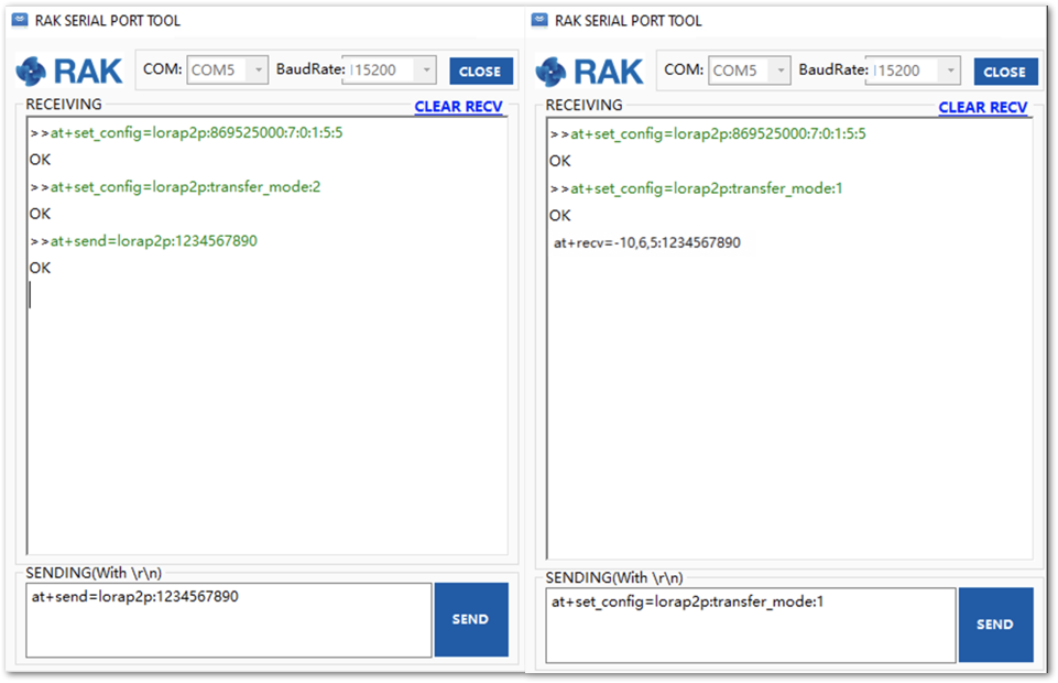 Figure 1: Sending a message from RAK unit 1(left) to RAK unit 2 (right)
Bluetooth Interface
Starting with the firmware version V3.0.0.6, there are three BLE modes in the RAK4600 module: Peripheral mode, Central mode, and Beacon scan mode.
- Peripheral mode: In this mode, you can scan RAK4600 BLE and connect with it using your normal mobile devices.
- Central mode: The RAK4600 BLE will not broadcast so that your normal mobile devices will not be able to scan it, but it is useful for IoT use case. For example, you can connect some BLE sensor nodes to the RAK4600. By setting the RAK4600 in the central mode, the RAK4600 acts as a BLE gateway. In the central mode, "Nordic UART Service" is supported.
- Beacon scan mode: The RAK4600 will scan the surrounding BLE signal. This mode is useful to scan for beacons like iBeacon near you.
For the central and beacon scan patterns, you need to use the API development of RUI to play its role. For BLE related API interfaces, refer to RUI API Reference.
By default, RAK4600 BLE will work in the peripheral mode so that you can configure it over BLE, including DFU. Every time after resetting, you have only 60 seconds to connect your mobile device with RAK4600 over BLE. If you don’t connect with RAK4600 in 60 seconds after resetting it, the RAK4600 BLE radio will not broadcast to reduce power consumption. There is no limitation once your mobile device has connected with RAK4600 over BLE in 60 seconds.
Surely, you can set RAK4600 BLE to work in the central mode. After a RAK4600 module reset, there will be 30 seconds that RAK4600 BLE radio works in the peripheral mode. In peripheral mode, you can connect to RAK4600 through BLE using your mobile device and configure RAK4600 over BLE. But if you don’t connect with RAK4600 through BLE in 30 seconds, the RAK4600 BLE radio will change to central mode automatically. In central mode, RAK4600 can not be scanned by your mobile devices until you change the work mode to the peripheral or reset RAK4600 again.
Miscellaneous
Upgrading the Firmware
Before you start working with the RAK4600, it is recommended to keep the RAK4600 updated to the latest version of the firmware. The latest firmware can be found in the software section of the RAK4600 Module Datasheet.
In the following sections, two (2) options for flashing new firmware in a RAK4600 are shown: Upgrade through DAPLink and Upgrade through BLE.
Firmware Upgrade Through DAPLink
Refer to RAKDAP1 Flash and Debug Tool Overview
Through BLE
Requirements
The table shows the minimum hardware and software required to perform the firmware upgrade through BLE.
| Mobile Phone | Android |
| DFU Package | https://downloads.rakwireless.com/#LoRa/RAK4600/Firmware/History-Release-Version/DFU-Package/ |
| nRF connect app | Nordic Semiconductor |
| nRF Master Control Panel (BLE) | Nordic Semiconductor |
Upgrade Procedure
Follow this procedure to upgrade the firmware in Device Firmware Upgrade (DFU) mode through the Bluetooth Low Energy (BLE) interface.
-
Download the latest DFU package of the RAK4600.
-
Install the mobile app named “nRF Connect” or “nRF Master Control Panel (BLE)", which are developed by the Nordic Semiconductor company.
-
Open the Nordic mobile app and scan for the BLE signal.
-
After resetting the RAK4600, its BLE interface should broadcast a device name with the format “RUI_XX:XX:XX” for 60 seconds, as shown in Figure 73. Refer to the Bluetooth Interface to know more.
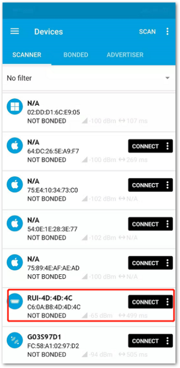 Figure 1: RAK4600 BLE device name
-
Select the device and press CONNECT.
-
Select Secure DFU Service and enable the “Indications” option by pressing the icon highlighted in red in Figure 74.
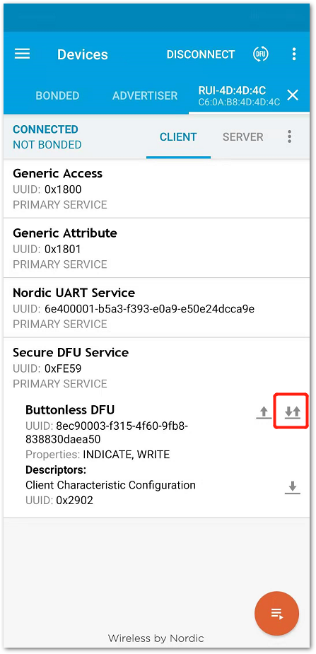 Figure 1: Enable the “Indications” option
- On the Buttonless DFU, click on the up arrow, then a pop-up menu should appear, as shown in Figure 75.
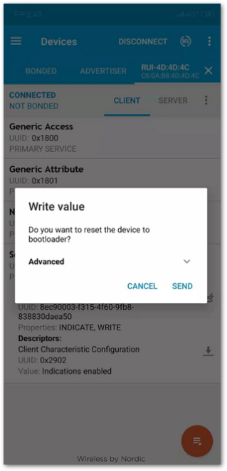 Figure 1: Pop up menu to enter to the bootloader mode
-
Press the SEND button to reset the RAK4600 and to enter into the DFU mode.
-
Scan again with the Nordic app, and a device named DfuTarg should appear, as shown in Figure 76.
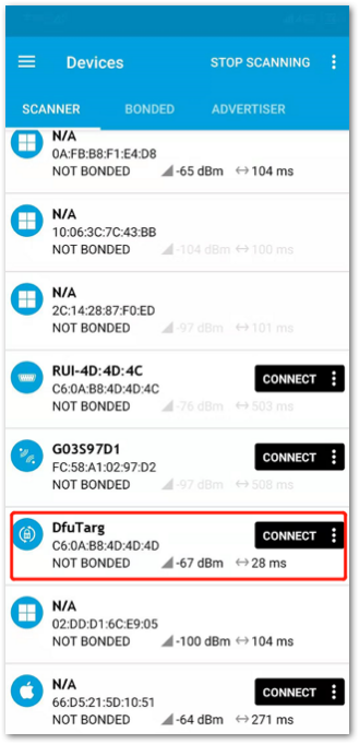 Figure 1: Nordic app scan with RAK4600 in DFU mode
-
Press CONNECT, then click the icon highlighted in red (DFU).
-
Select the Distribution packet (ZIP) option in the pop-up menu and press OK.
- Select the Distribution packet (ZIP) option in the pop-up menu and press OK.
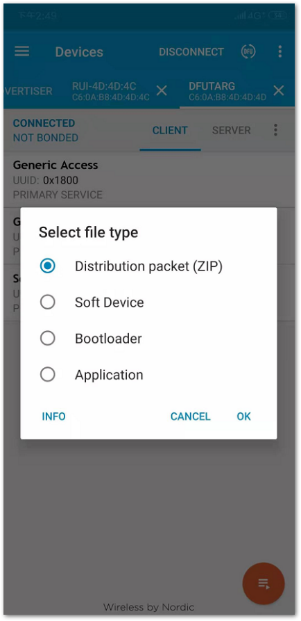 Figure 1: DFU mode options
- In the dialog menu, select the DFU package that was downloaded. After that, it will start to update the firmware through DFU over the BLE interface. The upgrade progress will be shown the same as Figure 79.
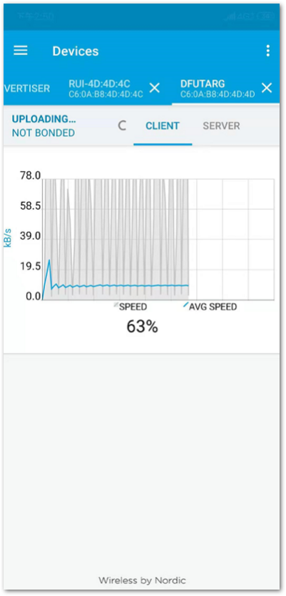 Figure 1: DFU firmware update progress
- Upon completion, the RAK4600 will restart automatically, and the DFU connection will be terminated.
Now, the RAK4600 is ready to work with the new firmware.
