Field Tester Plus for LoRaWAN FAQs & Troubleshooting
Find quick solutions to common problems, detailed explanations of testing concepts, and tips for optimizing your LoRaWAN field testing results.
Troubleshooting
Use the following table to identify common issues during field testing and take the recommended actions.
For Field Tester Plus, advanced field test results depend on the Field Test Data Processor Extension. If the extension is not installed, not running, or not correctly connected to the LNS through MQTT, the device may still join the network, but processed uplink data such as packet-loss rate, RSSI/SNR trend charts, test-point details, or CSV export may not work as expected.
| Issue | Possible Cause | Recommended Action |
|---|---|---|
| Join Failed | - Incorrect DevEUI, AppEUI, or AppKey - Wrong frequency band or regional settings - Gateway is out of coverage - Gateway or LNS is offline - Network server configuration issue | - Verify the LoRaWAN OTAA credentials - Check the frequency band and region settings on the Field Tester Plus - Move the device closer to the gateway - Ensure the gateway and LNS are online - Power cycle the device and try again |
| No data is shown after first boot | - The device has not sent a valid uplink yet - The device has not joined the network - The uplink has not been received by the LNS | - Wait for the device to send the next periodic uplink - Double-click the side button to trigger an uplink manually, if supported - Confirm that the device has joined the network successfully - Check whether the LNS has received uplink data |
| No uplink RSSI/SNR, packet-loss rate, or processed test data is shown | - The Field Test Data Processor Extension is not installed - MQTT integration between the LNS and the extension is not working - MQTT topic configuration does not match the LNS output - The connected LNS is not supported by the current extension configuration | - Confirm that the Field Test Data Processor Extension is installed and running on the gateway - Verify the MQTT broker address, port, uplink topic, and downlink topic settings - Check whether the extension is receiving MQTT messages from the LNS - Confirm that the gateway is connected to a supported LNS integration method - If the extension is not available or not integrated, only basic device-side information may be available |
| RSSI/SNR trend charts are not updating in the extension | - No new uplink data is being received - The Field Tester Plus is out of coverage - MQTT messages are not reaching the extension | - Confirm that the Field Tester Plus is still sending uplinks - Check whether the LNS is receiving uplink packets - Verify the MQTT connection between the LNS and the extension - Refresh the Device Overview page - Move the device closer to the gateway and test again |
| CSV report is empty | - No labeled test data exists | - Run Labeling Tests at the required test points before exporting - Make sure each test point has a valid label |
| High packet loss | - Weak or intermittent gateway reception - Physical obstructions between the device and the gateway - Device is too far from the gateway - RF interference in the test area - Data rate is too high for the current distance or environment | - Test in an open area or adjust the gateway position - Move closer to the gateway and compare the result - Use a lower DR for longer range - Increase TX power if allowed by the regional settings - Repeat the test at different times to check for intermittent interference |
| Poor RSSI or low SNR | - Long distance from the gateway - Antenna is not connected or not positioned properly - Device orientation affects signal quality - Obstacles, walls, metal structures, or cabinets block the signal - High noise or RF interference in the environment | - Check that the LoRa antenna is connected securely - Keep the device upright and avoid blocking the antenna - Test at different heights or nearby locations - Move away from metal structures or dense obstacles - Consider repositioning the gateway or adding another gateway |
| Multiple Field Tester devices are not all shown or processed | - MQTT topic is configured for a specific device EUI - The extension only receives messages from one application or device - Some devices are registered under a different application or LNS - Some devices have not joined or sent uplinks | - Keep MQTT topic placeholders unchanged if you want to process multiple devices - Verify that all Field Tester devices are registered in the expected application - Confirm that each device has joined the network and is sending uplinks - Check whether the extension receives MQTT messages for each device |
FAQs
1. Why Do We Need the Field Test Extension?
The Field Test Extension enables local signal processing on WisGateOS 2-based gateways, allowing the Field Tester Plus to perform full-featured testing, even in offline or indoor environments. It allows the system to:
- Process uplink and downlink signal metrics in real time
- Calculate packet loss and distance to gateways (when GPS is available)
- Export structured CSV reports for coverage analysis
2. Why Do I Need Downlink Data?
Downlink data helps you understand how well the device hears the gateway — not just how well the gateway hears the device. This is important for:
- Validating bi-directional communication (e.g., OTAA joins, confirmed messages)
- Ensuring control or command messages from the network can reach the device
- Diagnosing coverage issues in indoor or edge environments
3. Why Does the Field Tester Plus Come With Multiple Antennas?
LoRaWAN end devices in real-world deployments use different types of antennas — some with better range and gain, others with compact but lower performance. By testing with multiple antenna types, you can:
- Simulate different end device conditions (e.g., long-range sensor vs. compact tracker)
- Reflect the diversity of antenna performance across real deployments
- Collect more objective and realistic signal data by accounting for antenna gain differences
- Identify coverage weak spots that might be hidden when only using a high-gain antenna.
Using a lower-gain antenna during testing can help you detect borderline coverage areas, ensuring the network supports even the weaker RF devices.
4. Why Am I Only Seeing Downlink Metrics?
This usually means the Field Test data processor Extension is not installed or not integrated with your network server. In this case, the device operates in LinkCheck Mode, which allows:
- Basic downlink evaluation via LinkCheck responses
- No uplink RSSI, packet loss, or distance calculations
5. Can I Use the Field Tester Plus Indoors?
Yes — the Field Tester Plus works indoors, but with some limitations:
- GPS location and distance to gateway will not be available
- You must use manual location labels to identify test points in reports
- Signal conditions may vary due to obstructions like walls or metal structures
6. What Happens If I Forget to Label a Test Point?
If the location label remains NULL:
- That test point will not be saved in the CSV report
- Your data will be missing or unlabeled, which makes post-analysis difficult
7. What’s the Difference Between Field Tester Plus and Old Field Tester Pro?
| Issue | Possible Cause | Suggested Solution |
|---|---|---|
| Uplink RSSI/SNR | YES | |
| Uplink Packet Loss Rate | YES | |
| Downlink RSSI/SNR | YES | YES |
| Downlink Packet Loss Rate | YES | |
| Lat/Long GPS Info | YES | YES |
| Max Distance | YES | YES |
| Min Distance | YES | YES |
| Label Display | YES | |
| Label Setting | YES | |
| Stop or Start Sending Button | YES | |
| Last Refresh | YES | |
| Gateway EUI | YES | |
| No. of Gateway | YES | |
| Historical Data | YES | YES |
| Touchscreen Setting | YES | YES |
| Device Status | YES | YES |
| CSV Data Export | YES | |
| Offline Local Server | YES | |
| LinkCheck Mode | YES |
8. What Do the Fault Codes Mean?
| Fault Code | Description |
|---|---|
| GPS INIT FAILED | GPS module initialization error. Check module connection; replace GPS if issue persists. |
| TP INIT FAILED | Touch panel initialization error. Check screen connection; replace screen module if issue persists. |
| FLASH INIT FAILED | Internal flash error. May indicate RAK4631 failure; replace RAK4631 module. |
| LORA INIT FAILED | LoRa chip error. May indicate RAK4631 failure; replace RAK4631 module. |
| LOW VOLTAGE | Battery is critically low; recharge immediately. |
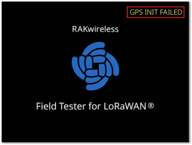 Figure 1: RAK10701-Plus GPS Failure
9. How Is the Distance to Gateways Calculated?
RAK10701-Plus calculates the estimated distance to gateways using GPS. Here’s how it works:
- The device obtains its GPS location (outdoor only).
- The gateway must have a known location (latitude/longitude set in the system).
- The distance between the device and the gateway is then calculated and displayed as:
- Nearest Gateway Distance
- Farthest Gateway Distance
- The unit of distance is meters, with a minimum unit of 250 meters.
Note: This feature only works in outdoor environments with active GPS.
10. How Is Packet Loss Calculated?
Packet loss is calculated based on the frame sequence number. Each uplink or downlink message carries a frame sequence number in the application layer data. The sequence number increments by 1 for each packet sent. Here’s the calculation method:
Frame Sequence Number:
Uplink messages use 2 bytes for the frame sequence number, with a range of 1-65535. Downlink messages use 1.5 bytes (12 bits) for the frame sequence number, with a range of 1-4095.
When the frame sequence number exceeds the maximum value, it will restart from 1.
Packet Loss Rate Calculation:
Both uplink and downlink packet loss rates use a sliding window method with a window size of 50. Each time a message is received, the frame number is added to the sliding window. If the window contains fewer than 50 packets, the actual number of received packets is counted. When the sliding window is full (50 messages), the oldest frame number is removed from the window, and the latest frame number is added.
Example:
If the received frame numbers are 2, 4, and 5, the theoretical number of received packets is 5 - 2 + 1 = 4, and the actual number of received packets is 3, so the packet loss rate is (4 - 3) / 4 = 25%. After the window is full with 50 messages, the packet loss rate is calculated based on the most recent data in the window.
The sliding window will be cleared, and the frame number reset each time a label is updated.
11. Why does the Field Tester still show a 100% downlink packet loss rate even when the gateway signal coverage is good?
This issue is usually not caused by poor signal coverage. It is caused by an incorrect connection setup between the Field Tester Extension and the gateway.
If a Field Tester Plus connects to multiple gateways with the Extension enabled, downlink routing conflicts may occur. This can result in a reported downlink packet loss rate of 100%.
To resolve this issue, ensure the Field Tester Plus connects to only one gateway Extension at a time.
Before switching to another test gateway, disconnect the current Extension connection first.
12. Why are there no Field Test Extension logs in the gateway log?
The Field Test Extension does not directly participate in LoRaWAN communication. It relies on MQTT Integration to subscribe to uplink data from the Field Tester Plus.
If MQTT Integration is disabled, the Extension cannot receive uplink data or calculate link quality statistics. It also cannot send Field Test related downlink messages.
As a result, no Field Test Extension records will appear in the Gateway Log. The Field Tester Plus will also not function properly.