RAK2011 Quick Start Guide
Prerequisites
What Do You Need?
The following two sections will provide a list of the components and tools you need in order to get started with the development board. Some of those are included in the package, others you need to provide yourself.
Hardware
- RAK2011 WisLink Cellular BG96 Arduino Shield
- Cellular and GPS Antenna
- Hologram SIM Card
Software
Product Configuration
Connecting to a Network
Connect Through a USB Interface
Push the PWRKEY once in order to turn on the module after connecting the USB cable.
Install USB Driver
- Download the the Quectel BG96 Windows driver.
- Once downloaded, install the BG96 USB driver on the PC.
- After the Windows USB drive installation is complete, connect RAK2011 to a PC via a Type A to Micro B USB cable.
- Open the Windows’ Device Manager. It will show the following under Ports (COM & LPT):
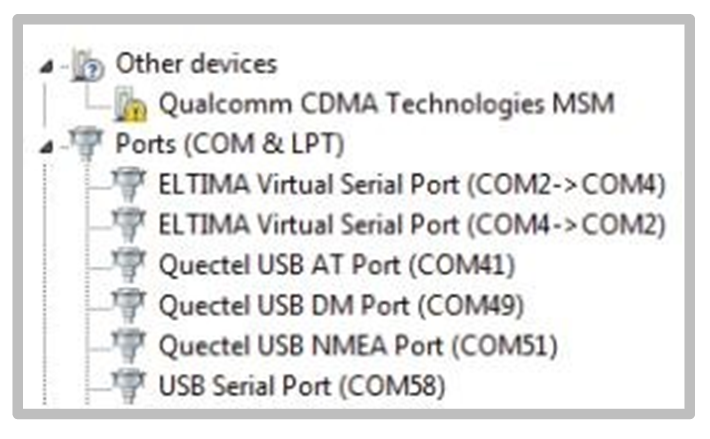 Figure 1: Windows Device Manager
Send AT Commands
- Download and install the the QCOM tool.
- Select Quectel USB AT Port corresponding to the COM port, then open the serial port tool.
- To know that the BG96 module is working normally, send the
ATcommand and the module will returnOK.
You can send additional AT commands to control the module. For more AT commands, refer to the BG96 AT Commands Manual.
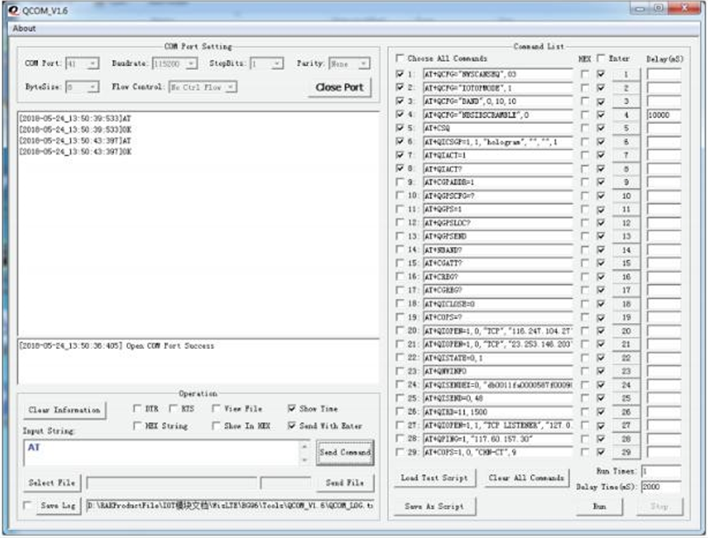 Figure 1: Send AT Commands
NB-IoT UDP Communication Test
Execute the following steps to test the NB-IoT UDP Communication:
- Plug in the NB-IoT SIM card.
- Connect the RAK2011 WisLink Cellular to a Windows PC.
- Select Quectel USB AT Port corresponding to the COM port.
- Open the serial port tool.
- Send the listed AT commands to have the BG96 module find a NB-IoT network.
China Telecom's NB-IoT SIM card is used in this example. Modify the AT commands as required according to the NB-IoT network being used to provide your service. For more information on AT commands, refer to the Quectel BG96 Network Searching Scheme Introduction.
AT+QCFG="NWSCANSEQ",03 // Set the scanning network to NB-IoT network
AT+QCFG="IOTOPMODE",1
AT+QCFG="BAND",0,10,10 // Set the scan channel to BAND5
AT+QCFG="NBSIBSCRAMBLE",0
You can also manually search the current network to connect. Use the following commands to do manual search and connection:
AT+COPS=? // Manually search the current network
AT+COPS=1,0,"CHN-CT",9 // Manually connect NB-IoT network
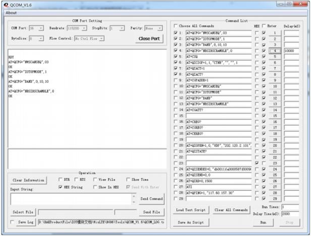 Figure 1: NB-IoT UDP Communication Test
- After setting the configuration, send
AT+CSQto check network signal strength. If there is a signal strength value, it indicates the module has connected to NB-IoT network. You can also sendAT+CGREG?to check the connection status of the network to determine whether or not to connect to the network:
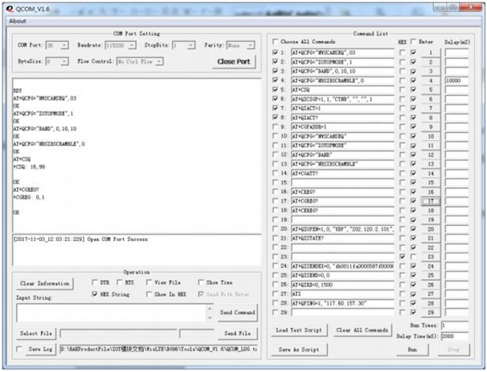 Figure 1: Check Network Signal Strength
- After connecting to the network, you need to set up the APN and activate the APN network. You can set the APN by sending the following commands:
AT+QICSGP=1,1,"CTNB","","",1 // Set APN parameters
AT+QIACT=1 // Activate APN
AT+QIACT? // Query the APN assigned IP address
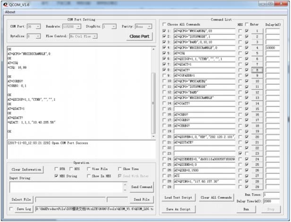 Figure 1: Setup and Activate APN
- After activating the APN, you can establish a UDP connection. (In China Telecom’s NB-IoT network, you must first inform the operator of your server’s IP address. The operator will make binding before the connection is successful. The behavior of other networks might be different).
AT+QIOPEN=1,0,"UDP","202.120.2.101",123,0,0 //Establish UDP connection
AT+QISTATE? // Query connection is successful
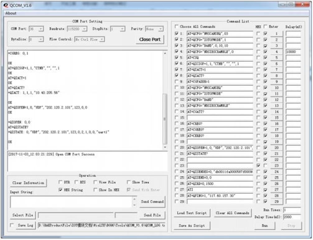 Figure 1: Establish UDP Connection
- When sending data to the server, there will be a prompt to receive data "recv". If there is no prompt you can send the following commands to check if there is data reception:
AT+QISENDEX=0,"db0011fa0000587f0009031d00000000dd99732a8e147ae10000000
0000000000000000000000000dd997618cb851eb8" // send data
AT+QISEND=0,0 // Query data is sent successfully
AT+QIRD=0,1500 // Check if there is data received, if there is,
print it out directly
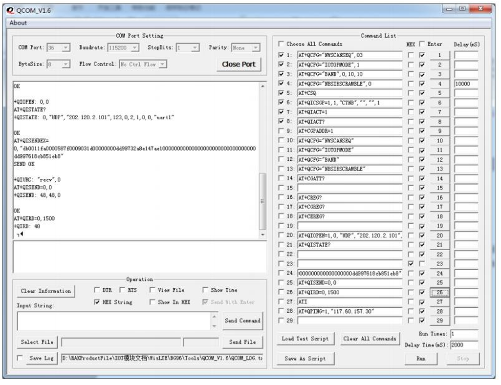 Figure 1: Check Data Reception
GPS Function Test
Execute the following steps to test the GPS Function:
- Plug in the module GPS antenna.
- Select Quectel USB AT Port corresponding to the COM port.
- Open the serial port tool.
- Send the commands listed below to control the module's GPS capabilities:
AT+QGPS=1     // Turn on GNSS
AT+QGPSLOC?   // Acquire Positioning Information
AT+QGPSEND    // Turn off GNSS
For detailed GPS command description, refer to Quectel BG96 GNSS AT Commands Manual.
- After sending the command, the GPS Function Test is completed.
Connect Through an Arduino Header Interface
The RAK2011 also supports Arduino headers as defined by Arduino UNO R3. Download the Arduino library for RAK2011 and then refer to the Datasheet for the RAK2011 Arduino Header pin definition.
Here is a test communication program to verify communication between an Arduino MCU base board and RAK2011.
void setup()
{
// put your setup code here, to run once:
Serial.begin(115200);
while (!Serial)
{
; // wait for serial port to connect. For native USB port only
}
}
void loop()
{
// put your main code here to run repeatedly:
if (Serial.available())
{
Serial.write(Serial.read());
}
}
Connect Through a Cellular
Create an Hologram Account
Hologram is the Connectivity Platform for the Internet of Things. You can connect devices, capture data, and manage your fleet through their complete IoT platform.
To start with, create an Hologram account/
Activate the Hologram SIM
- Login into your Hologram account and enter your Dashboard interface.
- Next, you need to activate your purchased Hologram SIM card by clicking on "Activate your first SIM".
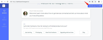 Figure 1: Activate you first SIM
- Enter the activation interface according to the given prompts. Then fill in the information to complete the activation of the SIM card.
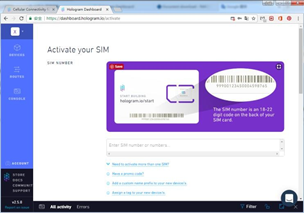 Figure 1: Input your SIM information
- Then enter the SIM card information interface. After waiting for a period of time, you will see the "Live" status.
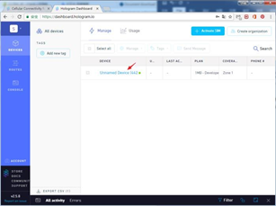 Figure 1: Manage your SIM card
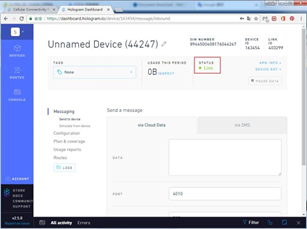 Figure 1: SIM card Status
Send Data
Insert the SIM card into the board’s slot, and then connect the board to the computer through the connection cable.
LTE antenna needs to be connected.
Find the port number of the AT Port and use the QCOM serial port tool to connect the board. Then send the following AT command. For the AT command details, see the AT command manual)
AT+COPS=?                     // Find nearby network information
AT+COPS=1,0,"CHINA MOBILE",0 // Manually set up a connected network
AT+CREG?                     // Check whether the device is registered on the network
AT+QNWINFO                   // Query connected network information
AT+COPS?                     // Query the connected web server information
AT+QICSGP=1,1,"hologram","","",1         // Set APN network to hologram
AT+QIACT=1                  // Activate the APN network
AT+QIACT?                   // Query the APN assigned IP address
AT+QIOPEN=1,0,"TCP","23.253.146.203",9999,0,1      // Create a TCP, connection hologram test server
AT+QISEND=0,48                                     // Send data, send data length is 48
{"k":"bZmmdbAg","d":"Hello,World!","t":"TOPIC1"}   //Send Packets.The data format is a hologram-defined format.( For details, see: https://hologram.io/docs/reference/cloud/embedded/ )
AT+QISEND=0,0      // Query data is sent successfully
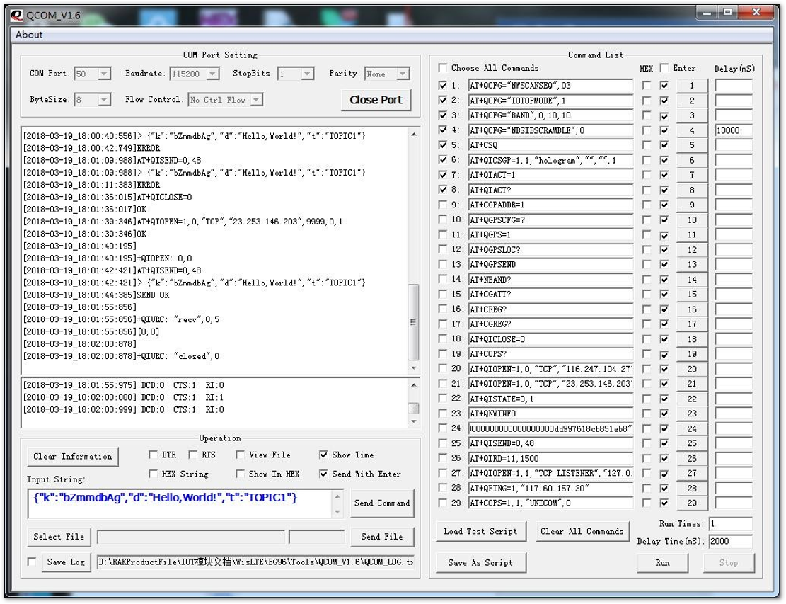 Figure 1: Sending query data
If the data is sent successfully, you can see the sent information on your interface of the Hologram Dashboard.
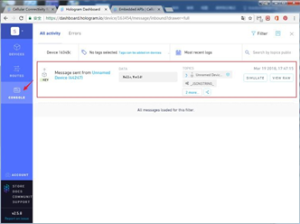 Figure 1: Data is sent successfully
Receive Data
Receiving data is similar to sending data, except that the established socket is different. The receiving data is established as a TCP server. The AT commands sent are shown below:
COPS=?       // Find nearby network information
AT+COPS=1,0,"CHINA MOBILE",0   // Manually set up a connected network
AT+CREG?      // Check whether the device is registered on the network
AT+QNWINFO      // Query connected network information
AT+COPS?      // Query the connected web server information
AT+QICSGP=1,1,"hologram","","",1    // Set APN network to hologram
AT+QIACT=1     // Activate the APN network
AT+QIACT?     // Query the APN assigned IP address
AT+QIOPEN=1,1,"TCP LISTENER","127.0.0.1",0,2020,0     // Create a TCP server, use local IP, port 2020
AT+QIRD=11,1500    // Read the received data, 11 is the returned Socket identifier
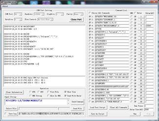 Figure 1: Create a TCP server
After creating a successful TCP server, you need to return to the Hologram Dashboard interface, click on the "send to device" button, and then fill in the data to be sent. The PORT is the TCP server port of your board. Fill in and click "Send data message".
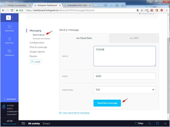 Figure 1: Send a message
After sending the data in the Hologram Dashboard, the board will receive a message of "recv, 11" indicating that the board have already received the data. At this time, sending the AT+QIRD=11,1500 command to obtain the received data.
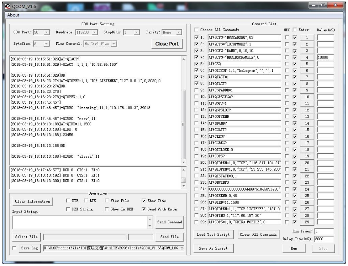 Figure 1: Data is received