RAK2470 WisNode Bridge Serial Prime Quick Start Guide
This guide covers the basic hardware setup, local configuration, network connection, and installation required before deployment.
Hardware Preparation
Package Contents
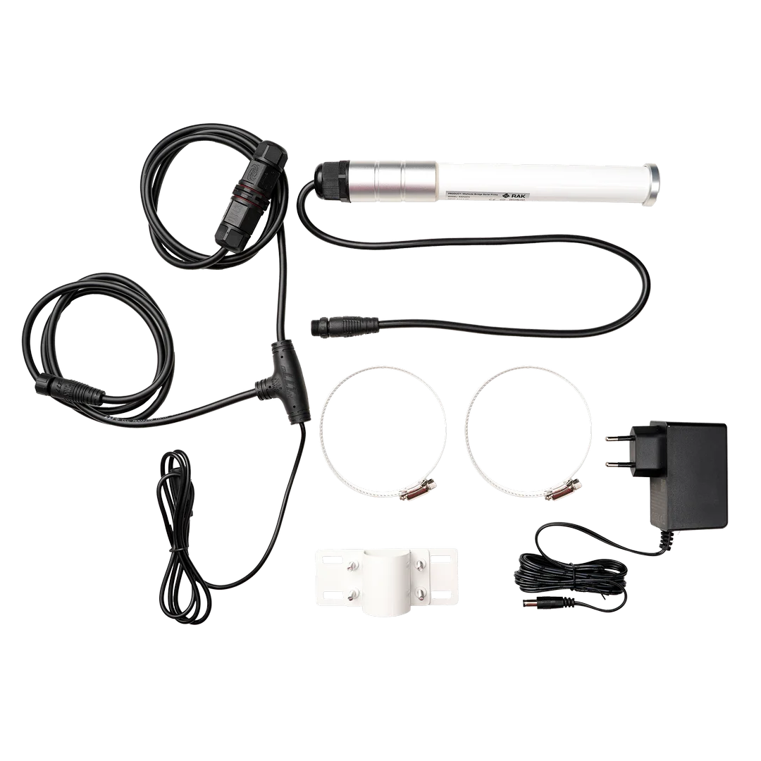 Figure 1: RAK2470 Package Inclusions
- One (1) RAK2470 WisNode Bridge Serial Prime
- One (1) Mounting Kit
- One (1) T-Type Conversion Cable
- One (1) Power Adapter
Additional Requirements
Before installation, ensure the external devices are ready.
- RS-485 devices
- Configuration Cable for WisNode Bridge Serial Prime RAK2470
Hardware Assembly
Connect the RS485 Device
Connect the external RS-485 devices to the corresponding terminal blocks on the RAK2470 (see Connect RS485 Device to the RAK2470).
This allows the RAK2470 to exchange RS485 data with the connected device and forward the data over LoRaWAN®.
Power On the Device
The RAK2470 supports a 5–12 VDC input. When using the included 12 VDC power adapter, connect it to the DC power port of the T-type conversion cable.
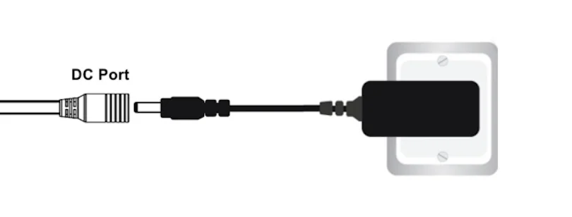 Figure 1: Power interface connection
Network Setup Before Deployment
Before deploying the RAK2470 in the field, configure the RS-485 interface and LoRaWAN parameters locally to ensure proper operation and minimize on-site configuration issues.
Prerequisites
- A LoRaWAN gateway within range
- A Windows or macOS computer
- Download and install the IO.Box Desktop application.
After installation, launch the application to proceed.
Connect the RAK2470 to IO.Box
- Connect the RAK2470 to a computer via the USB configuration cable.
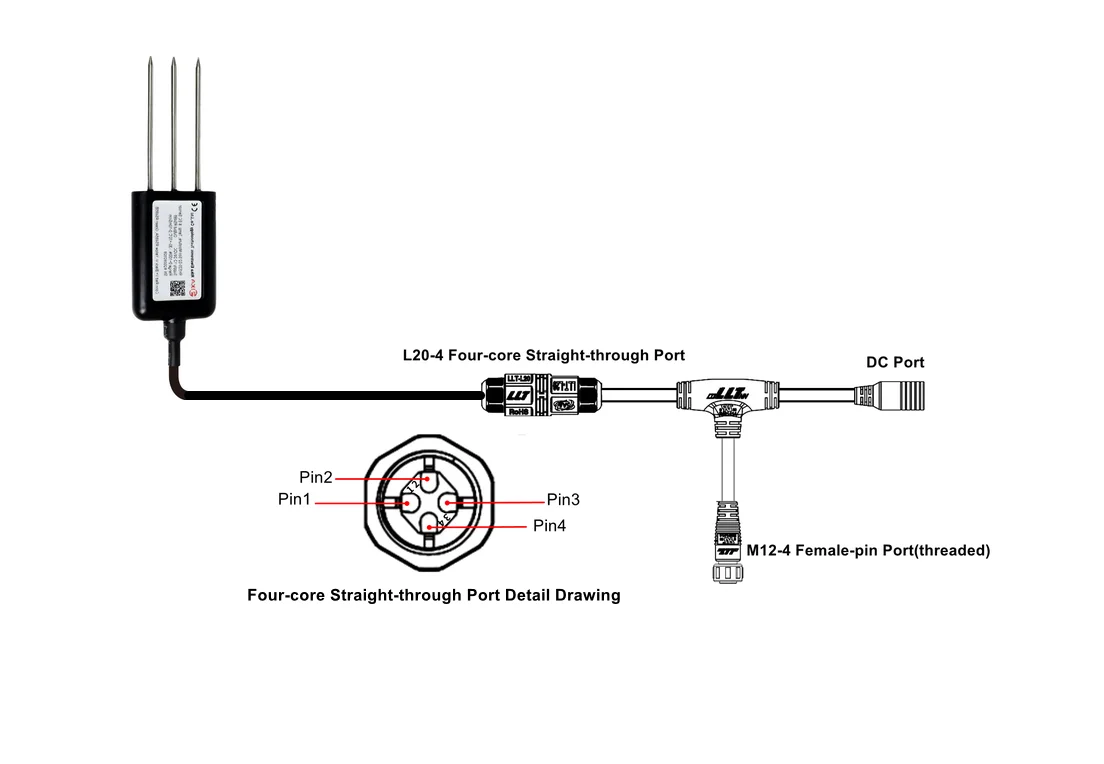 Figure 1: Data interface connection
 - Click Connect Device in the IO.Box console.
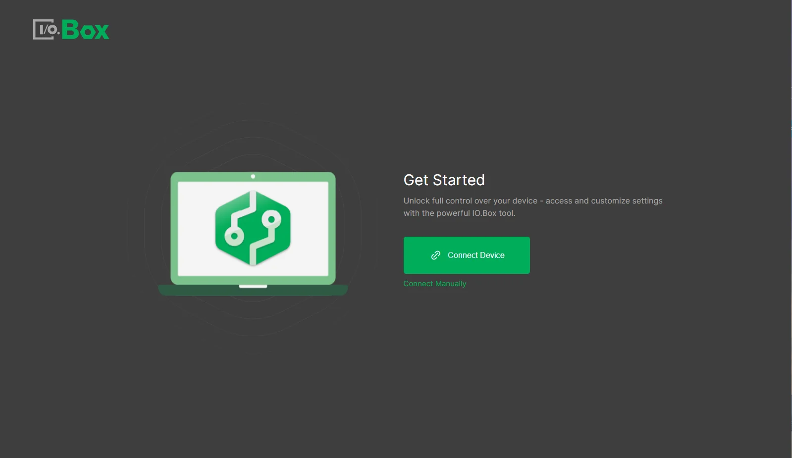 Figure 1: IOBox get startedImportant
- If no device is detected, the RAK2470 may have exited Configuration Mode. After entering Configuration Mode, the device opens a 30-second configuration window by default. Performing configuration operations during this period extends the window, up to a maximum of 30 minutes. If the device fails to join the LoRaWAN network within the configuration window, it remains in Configuration Mode, allowing you to modify the configuration and retry the join process.
- If the device successfully joins the LoRaWAN network and the configuration window expires, the configuration port closes, and the serial port switches to RS485 communication. To re-enter Configuration Mode, power cycle the device and reconnect it through IO.Box.
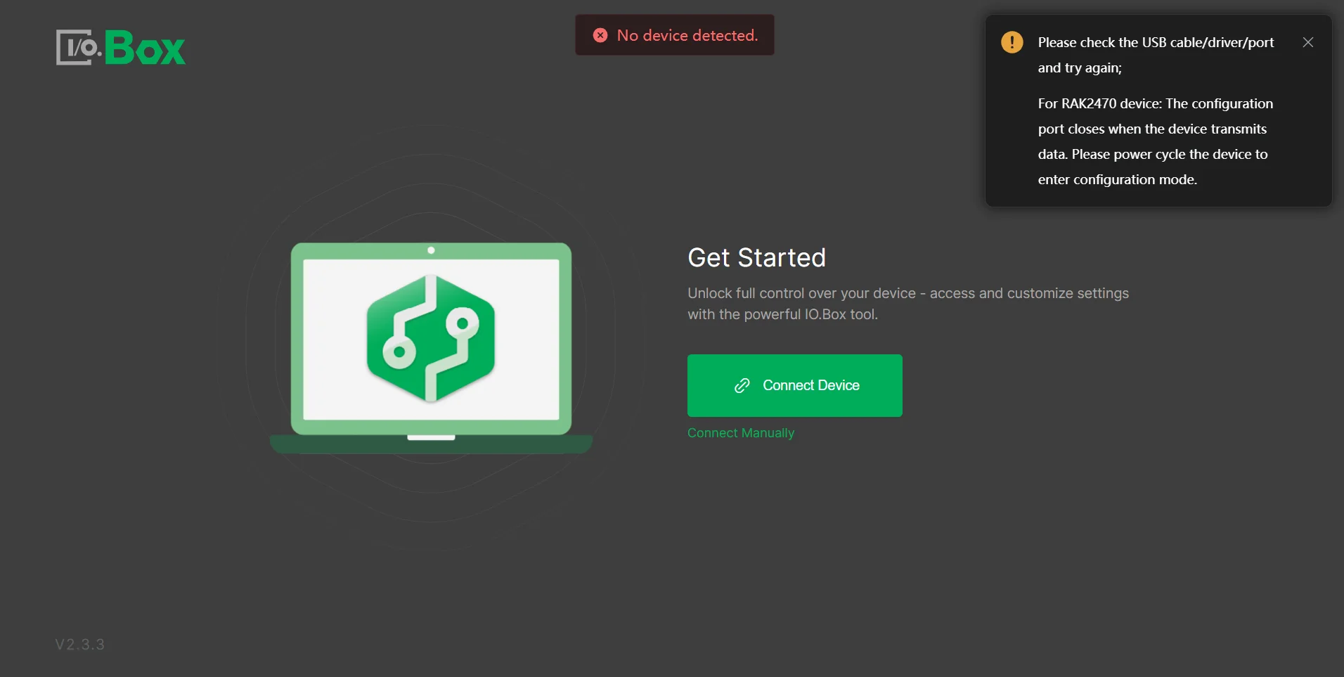 Figure 1: No device error
 - On the IO.Box dashboard screen, you can see information about the devices connected to the PC in the form of a list of connected devices with device models and EUIs. Choose the device that you wish to configure via the Connect button next to it.
Configure the RS485 Interface
After connecting the RAK2470 to IO.Box, configure the RS485 communication parameters and polling tasks according to the connected RS485 device. Refer to RS485 Interface Configuration.
Configure LoRaWAN Parameters
After configuring the device interfaces, select LoRaWAN from the left menu in IO.Box to configure the LoRaWAN parameters. Once completed, the device can join the LoRaWAN network and transmit data.
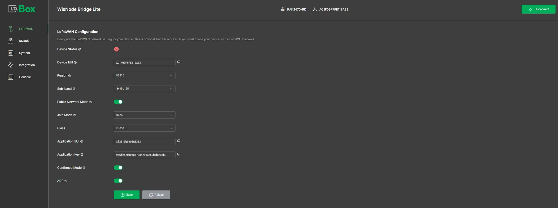 Figure 1: LoRaWAN tab
- Device EUI: This is the unique identifier provided by RAKwireless.
- Region: The LoRaWAN region/band.
- Join Mode: Choose between OTAA and ABP according to LoRaWAN protocol.
- Class: The LoRaWAN Class (C).
- Application EUI: Enter the unique identifier for your application.
- Application Key: Enter the unique secure key for your application.
- Confirm Mode: Activate to receive confirmation messages from the network server for each uplink.
- ADR: Enable Adaptive Data Rate allowing the network server to control the data rate for your device.
- DataRate: Manually set the data transmission rate. Lower rates extend coverage but increase transmission time and power usage. Choose based on the distance and signal quality to the gateway.
- TX Power Level: Adjust the transmission power level. The lower the number the higher the power. 0 is the maximum allowed in the selected region and each incrementation of 1 to the number reduces the power by 2 dBm.
- Data Collection Period: Set up the global data report period of the device. Range: 60–86400 in seconds.
- LoRaWAN Status: Indicates the activity of the device in the LoRaWAN network.
Connect the RAK2470 to LoRaWAN Network Server
After configuring the device interface and LoRaWAN parameters, register the RAK2470 with your LoRaWAN Network Server (LNS). Make sure that the region, activation mode, and corresponding device credentials match the settings configured on the RAK2470.
After the device joins the network, verify that data from the connected interface is received by the LNS.
For detailed steps, refer to Connect the RAK2470 to LoRa Network Server.
Installation and Deployment
RAK2470 allows for pole mounting. Follow the provided installation steps to ensure secure mounting.
- Fix the RAK2470 to the mounting kit with four (4) M4*20 screws.
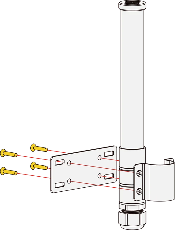 Figure 1: Fixing the device to the mounting kit
 - Using two (2) steel strips, fasten the RAK2470 on the pole.
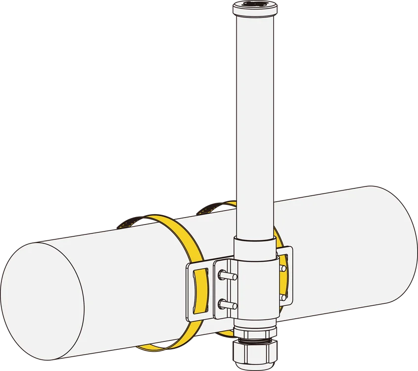 Figure 1: Using the steel stripsNOTE
The pole diameter supported by the included steel strips is 55~80 mm.
- Link the connector of the RAK2470 to the corresponding port.
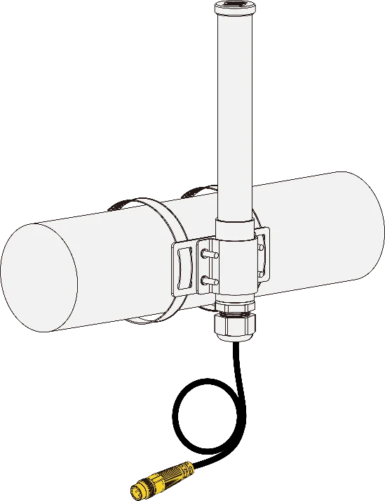 Figure 1: Adding the connector
After installation, power on the device and verify uplink data transmission. Once communication is confirmed, the device is ready for normal operation in the field.
Next Steps
After completing the basic device setup, refer to the following guides based on your application:
- Initial Configuration Uplink – Understand the configuration information automatically reported after LoRaWAN network activation.
- Remote Configuration via LoRaWAN Downlink – Read or modify supported device parameters remotely through LoRaWAN downlinks.


