RS485 Device Configuration Guide
Prerequisite
Before connecting the sensor to the RAK2470 device, make sure to prepare the necessary items listed below.
- RAK2470 WisNode Bridge Serial Prime
- Configuration Cable for WisNode Bridge Serial Prime RAK2470
- Gateway in range (for testing)
- A Windows/macOS Computer
- IO.Box (latest version recommended)
Download the installation package for Windows and macOS. You can also find previous versions here: RAKwireless Downloads Center
Connect the RAK2470 to the Sensor
There are two ways to connect devices to RAK2470:
-
When the device has its own power source (e.g. a MPPT solar charge controller), it can be directly connected to the connector on the RAK2470.
-
When the device cannot provide power, it needs to be powered through the T-type conversion cable as follows.
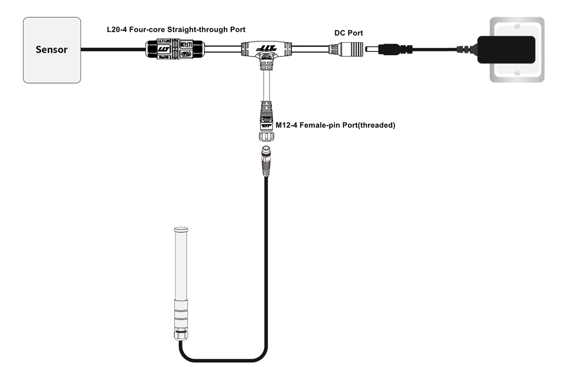 Figure 1: Connecting the bridge to a device
Data Interface Connection
The sensor is connected through the L20-4 port of the T-type conversion cable. In this section, the RK520-02 Soil Moisture, Temperature, and Electrical Conductivity sensors will be used as an example.
- Pin 1: Connect to the positive terminal of the sensor's power cord.
- Pin 2: Connect to RS485-A of the sensor.
- Pin 3: Connect to RS485-B of the sensor.
- Pin 4: Connect to the negative terminal of the sensor's power cord.
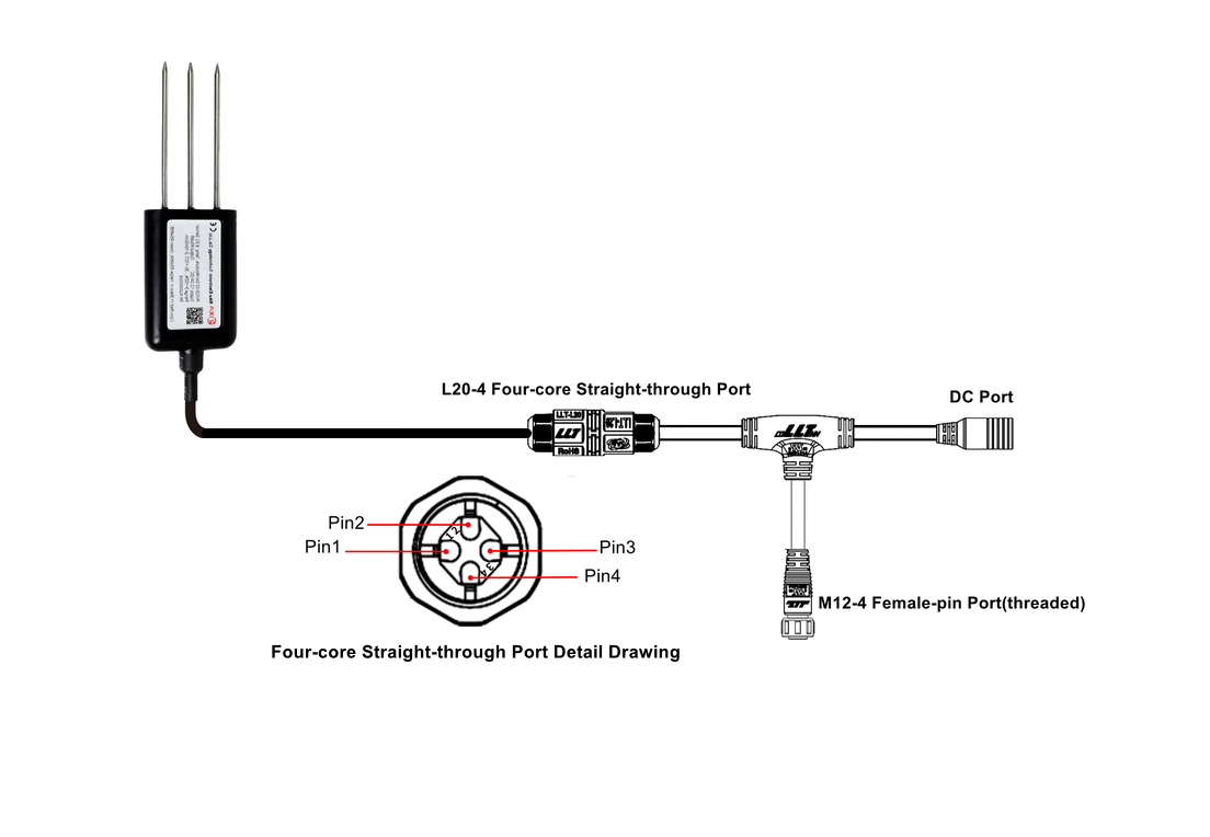 Figure 1: Data interface connection
RAK2470 Connection
If you are using the RAK2470 for the first time, you need to configure it. To do so, connect the RAK2470 to your PC using the USB configuration cable.
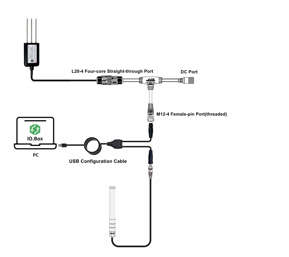 Figure 1: RAK2470 Connection
Power On the Device
The RAK2470 device can be powered with 5 ~ 12 VDC wide-range input via a 12 VDC adapter. Simply connect the adapter to the DC port of the T-type conversion cable.
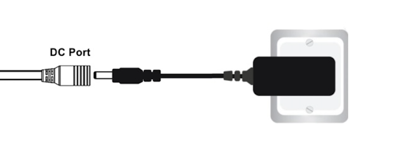 Figure 1: Power interface connection
RS485 Interface Configuration
RS485 interface parameters must exactly match the sensor’s communication settings. Incorrect configuration will result in Modbus communication failure.
Go to the RS485 tab and configure the interface based on the connected sensor or device. Remember to save the settings.
The parameters shown below are specific to the example sensor. For detailed parameter definitions, refer to RS485 Interface Configuration.
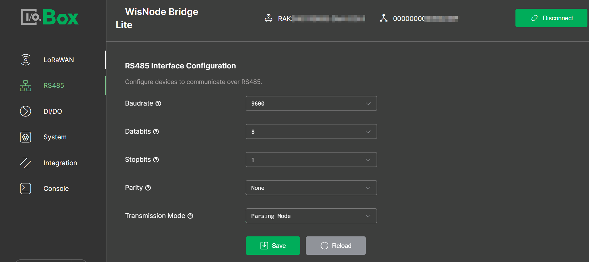 Figure 1: interface-configuration
- Baudrate: Select the RS485 communication speed (bits per second).
- Databits: Select the number of data bits for each character in the RS485 communication.
- Stopbits: Select the number of stop bits used in the RS485 communication.
- Parity: Select the parity setting for the RS485 interface.
- Transmission Mode: Defines how RS485 data is processed and transmitted to the LoRaWAN network. In this example, Parsing Mode is selected, which converts RS485/Modbus data into structured LoRaWAN payloads.
The following are the basic communication parameters of the RK520-02 soil moisture, temperature, and electrical conductivity sensor:
| Parameter | Definition |
|---|---|
| Format | 8-bit binary |
| Data bit | 8-bit |
| Parity | No |
| Stop bit | 1 |
| Error checking | CRC |
| Baud rate | 9600 |
Add Modbus Poll Task
This section demonstrates how to create Modbus polling tasks for temperature, humidity, and electrical conductivity (EC). If you need to create a polling task with a raw binary data type, refer to (Optional) Add a Raw Data in Binary Poll Task.
-
The available polling task parameters vary depending on whether Use Reference Address is enabled or disabled.
-
This section uses Use Reference Address disabled as the example. For details about both methods, refer to Add Modbus Poll Task.
- In the Modbus Poll Task menu, click +Add for a new poll. You will see the Polling Task parameters that need to be configured.
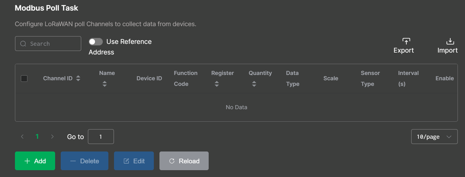 Figure 1: Add poll task
-
Fill in the relevant fields according to the specific sensor’s datasheet, as shown in the screenshot and parameter settings below. Here we create a temperature polling task as an example.
NOTEOnly parameters directly related to these polling tasks are described here. Other parameters remain at their default values. For more details, refer to Add Modbus Poll Task.
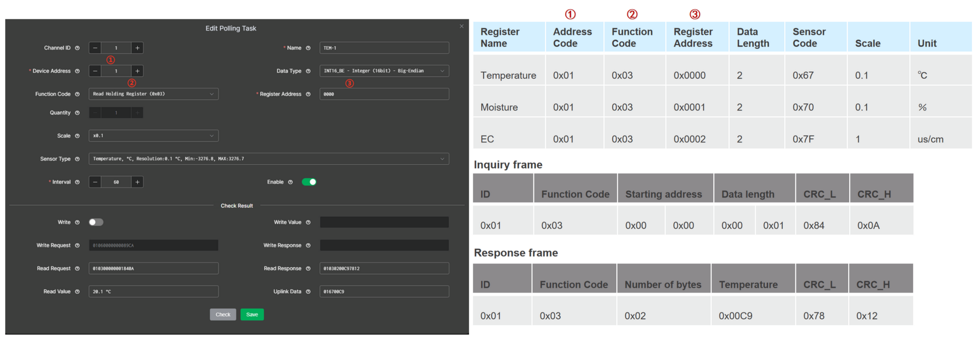 Figure 1: Add temperature polling task
-
Channel ID: Identifier of the polling task.
-
Device Address: The unique address of the connected device on the RS485 bus, obtained from the device manual.
-
Function Code: Specifies the task's Modbus operation type (read or write), obtained from the device manual.
-
Register Address: The target register or coil address used in the Modbus request, obtained from the device manual.
-
Scale: To adjust the raw data from the Modbus response to the desired units.
-
Sensor Type: Select the unit or category that best matches your slave device output (used for correct interpretation and presentation).
Click Check to perform automatic validation. If the returned values are correct, save the polling task.
-
Read Request: Displays the Modbus command generated from the selected settings, which is used to communicate with the device.
-
Read Response: Displays the response received from the Modbus slave device.
-
Read Value: Shows the parsed value extracted from the Response, based on the configuration above.
-
Uplink Data: Displays the data payload format that will be sent to the server, based on the configuration above.
- Create moisture and EC polling tasks in the same way.
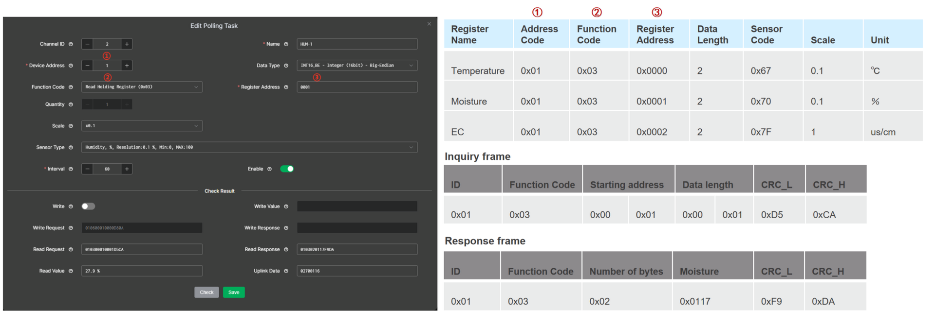 Figure 1: Add moisture polling task
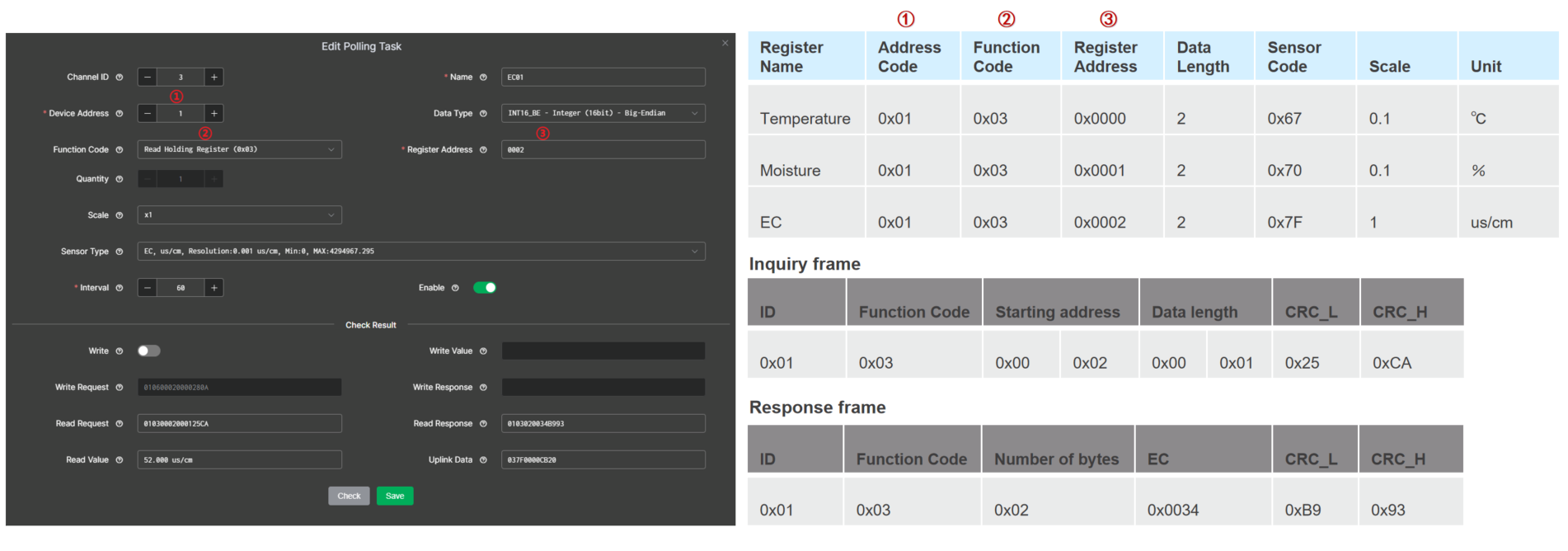 Figure 1: Add EC polling task
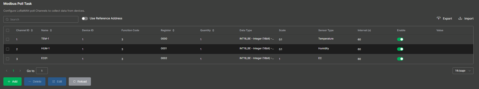 Figure 1: Created polling tasks
The RAK2470 WisNode Serial Prime has one channel used for both the RS485 communication with the sensor, and in the setup procedure. This is why you cannot see the requested data (polled data) from the sensor during setup.
(Optional) Add a Raw Data in Binary Poll Task
- In the Modbus Poll Task menu click +Add for a new poll. You will see the Polling Task parameters that need to be configured.
Figure 1: Add poll task- Fill in the relevant fields according to the specific sensor's datasheet. Here we create a temperature polling task as an example.
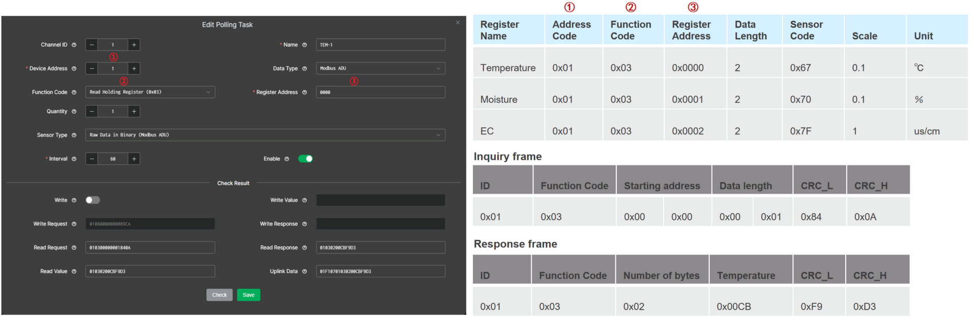 Figure 1: Add temperature polling task
-
Channel ID: Enter the identifier for the polling task.
-
Device Address: The unique address of the connected device on the RS485 bus, obtained from the device manual.
-
Function Code: Specifies the Modbus operation type (read or write), obtained from the device manual.
-
Register Address: The target register or coil address used in the Modbus request, as specified in the device manual.
-
Data Type: The data type of the Modbus response. In this document, select
Modbus ADU. -
Sensor Type: Select the unit or category that best matches your slave device output. In this document, set it to
Raw Data in Binary (Modbus ADU).
Click Check to perform automatic validation. If the returned values are correct, save the polling task.
-
Request: Displays the Modbus command generated from the selected settings, which is used to communicate with the device.
-
Response: Displays the response received from the Modbus slave device.
-
Value: Shows the parsed value extracted from the Response, based on the configuration above.
-
Uplink Data: Displays the data payload format that will be sent to the server, based on the configuration above.
- Create moisture and EC polling tasks in the same way.
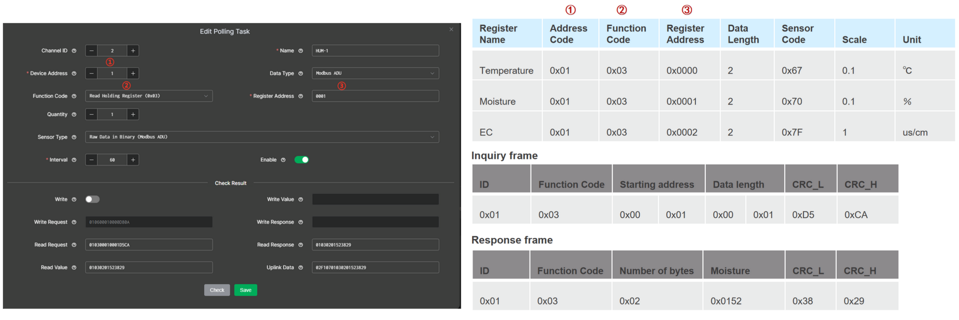 Figure 1: Add moisture polling task
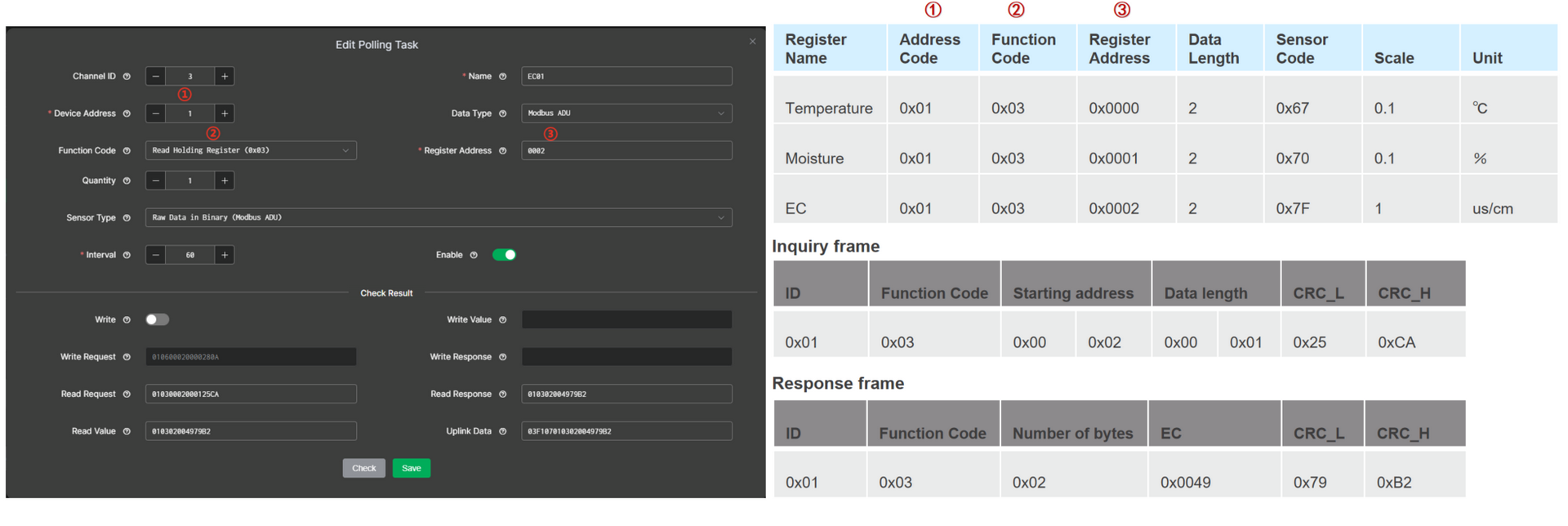 Figure 1: Add EC polling task
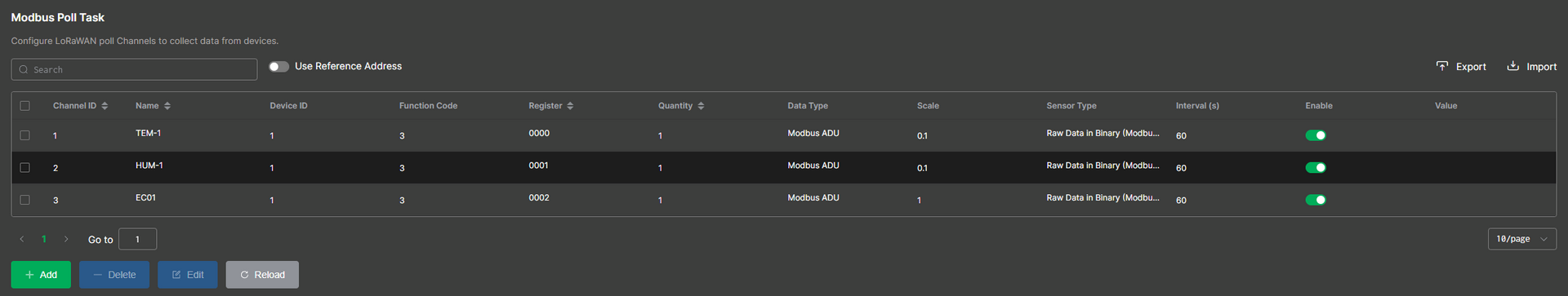 Figure 1: Created polling tasks
The RAK2470 WisNode Serial Prime has one channel that is used both for the RS485 communication with the sensor and in the setup procedure. This is why you cannot see the requested data (polled data) from the sensor during setup.
Connect Bridge IO to LoRa Network Server for Uplink
This section provides you with operation guidance for connecting the RAK2470 to different LoRaWAN network servers.
Before connecting to the LNS, ensure that you have completed Configure LoRaWAN Parameters in IO.BOX.
Built-in Network Server
In this section, the RAK2470 WisNode Bridge Serial Prime will be connected to a RAKwireless gateway. For the gateway, the built-in LNS will be used.
Set-up the Built-in Network Server
- Start by accessing the gateway. Refer to the appropriate WisGateOS 2 user manual depending on the gateway you are using:
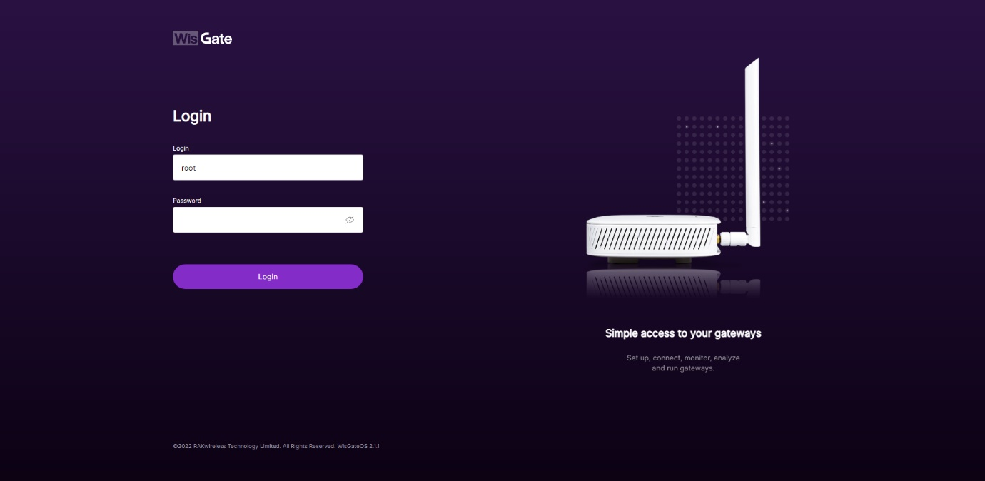 Figure 1: WisGateOS 2 login page
- Once logged in, head to the LoRa menu.
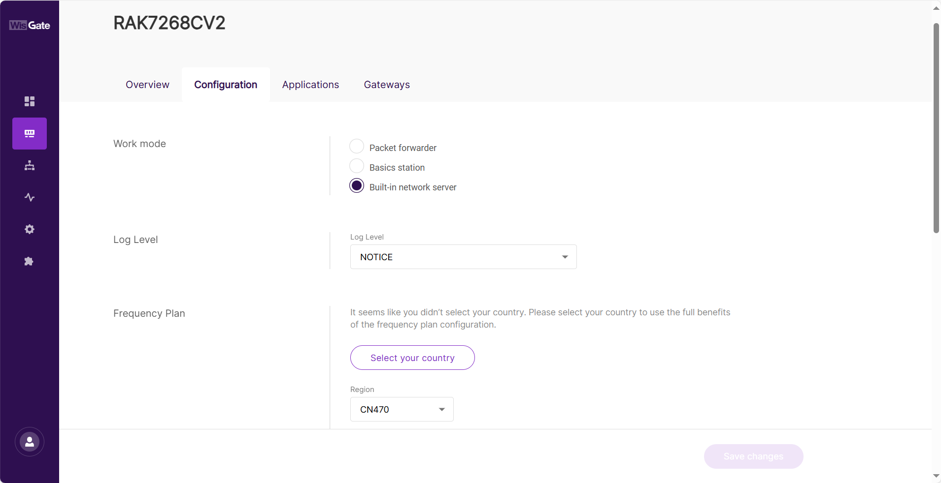 Figure 1: LoRa page
- By default, the gateway works as a Built-In Network Server. If not, switch the Work mode to Built-in network server.
Adding Application
- Once the gateway is in Built-in network server mode, head to the Applications tab.
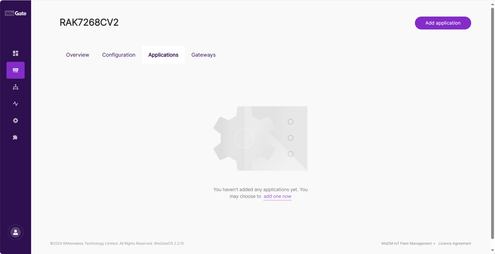 Figure 1: Create Application in the Built-In Network Server
- Click the Add application button or add one now link to add a new application. On the new page, fill in the following information:
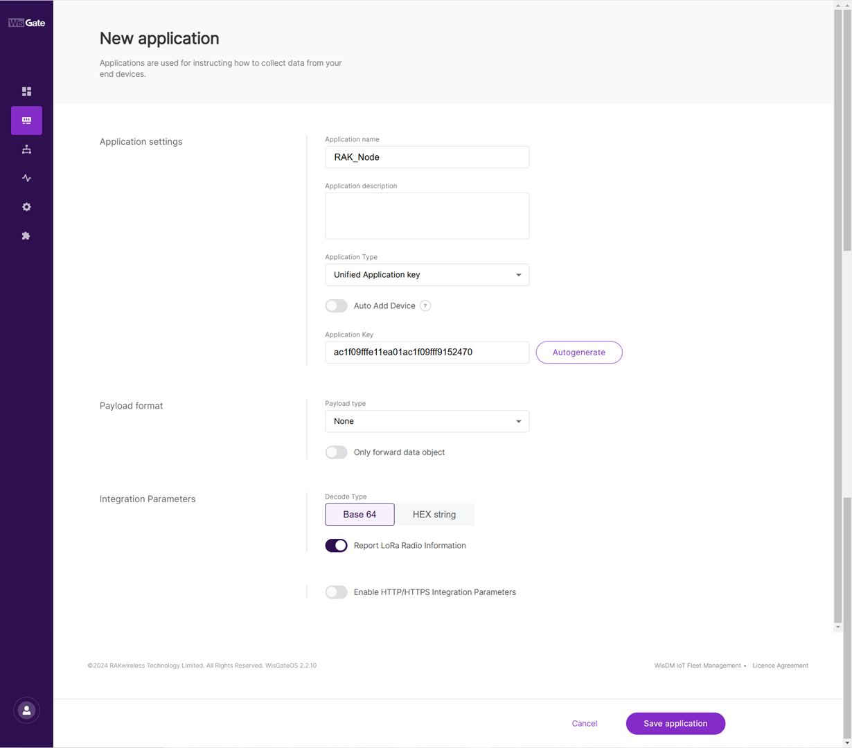 Figure 1: Adding application
- Application name: type a name for the application.
- Application Type: from the drop-down menu select the type of application. In this document, choose Unified Application Key.
- Unified Application key: All devices use the same application key. After selecting this option, the Application Key field will appear. This value must match the one configured on the end device. You can manually enter the application key or click Autogenerate to generate one automatically.
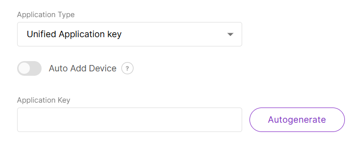 Figure 1: Unified application key
The Auto Add Device switch activates the Application EUI field. The device will be automatically added to the application after the application EUI and key verification.
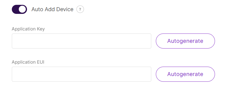 Figure 1: Auto add device
- Payload type: from the drop-down, select CayenneLPP payload type and turn on the Only forward data object feature.
-
Once set, click Save application to add the application.
-
After the application is added, head to the End devices tab. The devices should automatically register upon join request if you are using the Auto Add Device feature.
If that’s not the case, click the Add end device button. On the End device information page fill in the following information:
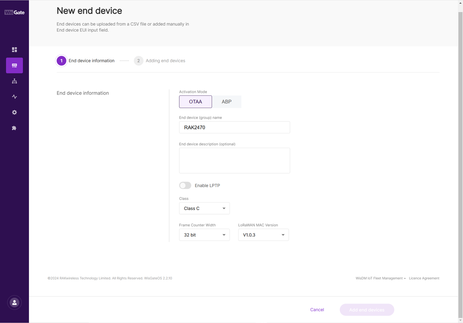 Figure 1: Successfully created application
- Activation Mode: choose the activation mode of your device.
- OTAA: Selected in this document.
- ABP: This mode pops up two additional fields:
- Application Session Key
- Network Session Key
- End device (group) name: the name of the device.
- Class: the class of the device.
- Frame Counter width: the width of the frame counter. Leave it as default.
- LoRaWAN MAC Version: the LoRaWAN MAC version.
Adding the Device
-
Once everything is set, click Add end devices to go to the page and add the device.
-
On the Adding end devices page, type the device EUI at the End Device EUI (main) and click Add to “End Devices list”.
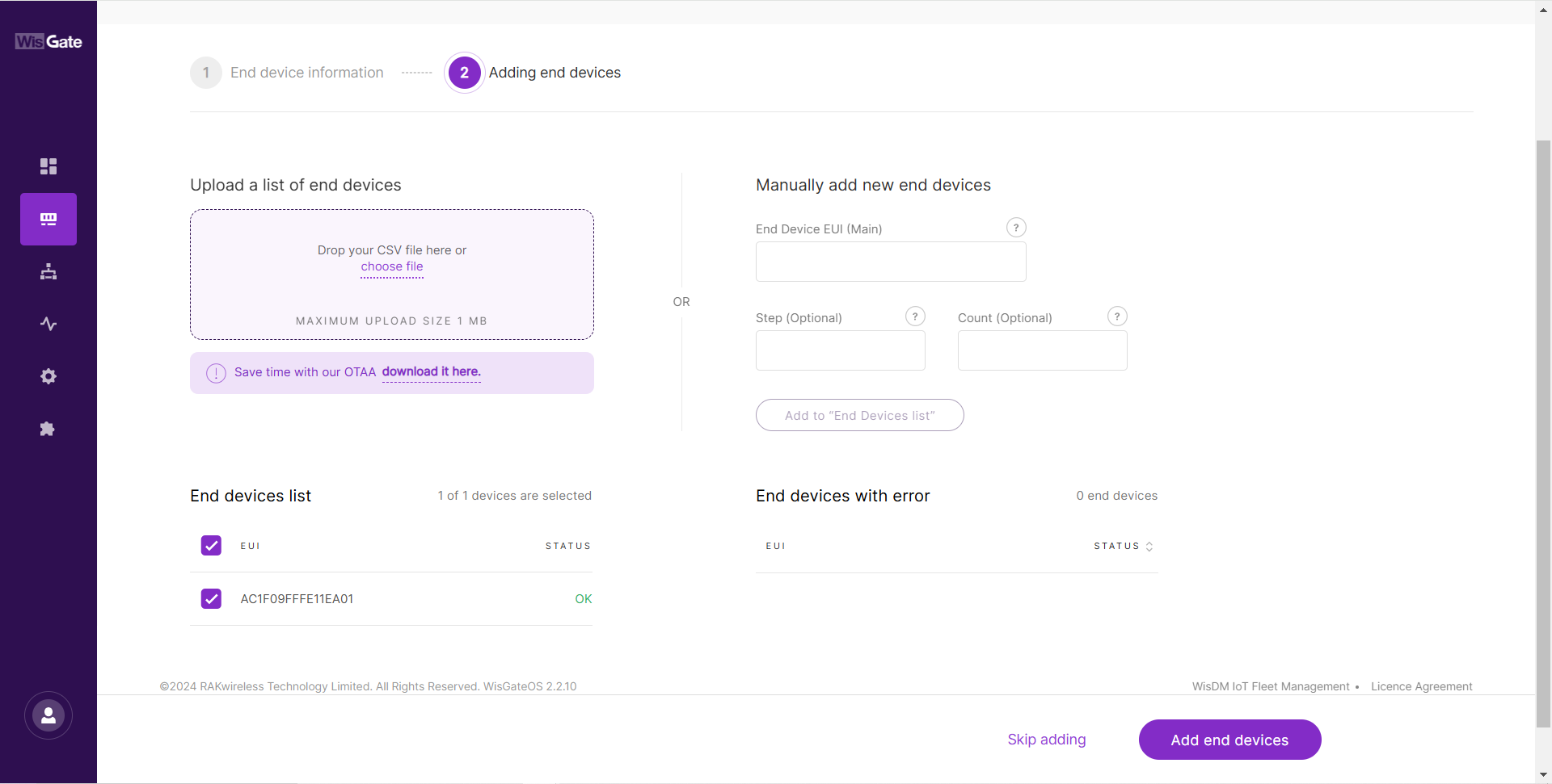 Figure 1: Adding end device
-
If the EUI is correct, the device will show in the End devices list.
-
If the EUI is not correct, the devices will show in the End devices with an error.
- Once the device is added to the End devices list click Add end devices. Confirm you are adding the device.
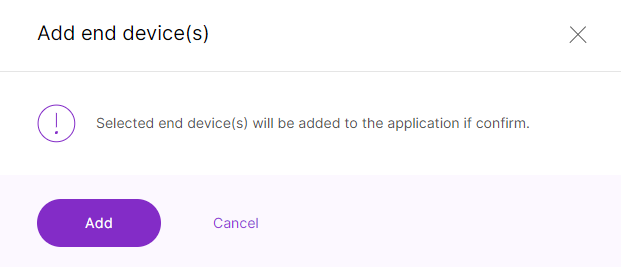 Figure 1: Confirmation message for adding a device
- After the device has successfully joined the LNS, you will see the LoRaWAN status in the IO.Box console toggles as activated. You might need to refresh the page.
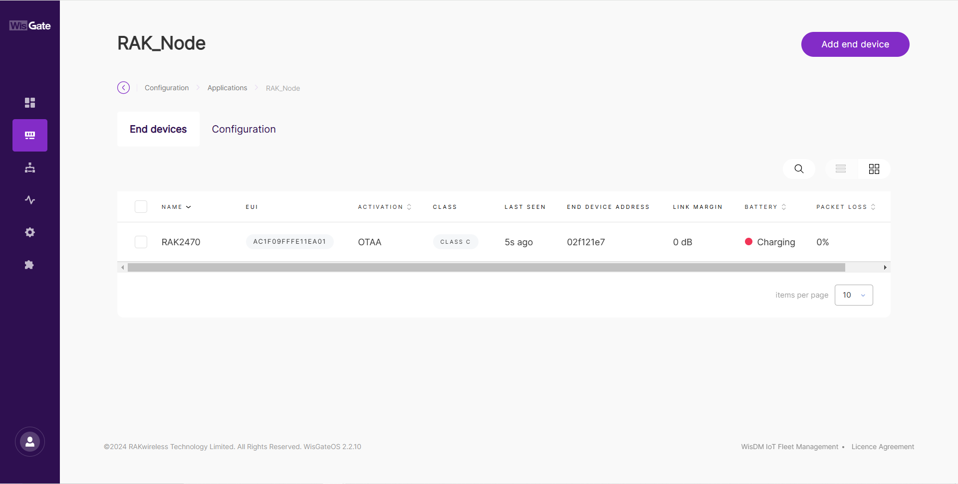 Figure 1: Device is online
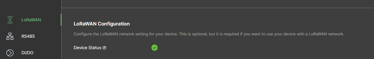 Figure 1: LoRaWAN status
Verify RS485 Uplink Data
The RAK2470 uses the same serial channel for IO.BOX configuration and RS485 sensor communication. Therefore, RS485-to-LoRaWAN® uplink forwarding is not available while the device is in Configuration Mode.
After you configure the LoRaWAN® parameters in IO.BOX, the device attempts to join the LoRaWAN® network. If the join is successful, the device sends a verification uplink and keeps the configuration window open for a short period. For details, see Instant Configuration Uplink.
During this period, if you send another configuration from IO.BOX within 30 seconds, the window is extended by 5 minutes, up to a maximum of 30 minutes. If no further configuration is received, the device exits Configuration Mode and displays the warning shown in the following figure.
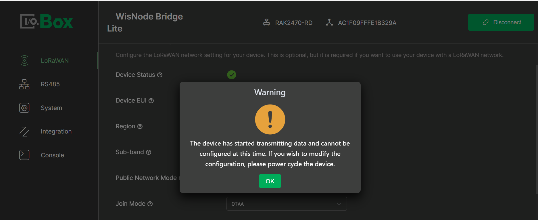 Figure 1: Exit Warning
Then the device enters Working Mode and starts forwarding RS485 uplink data through the LoRaWAN® network.
If the device fails to join the LoRaWAN® network, it remains in Configuration Mode. You can update the configuration and retry the join process. RS485-to-LoRaWAN® uplink forwarding starts only after the device joins successfully and exits Configuration Mode.
In Working Mode, you can view the uplink data in the gateway Web UI. The figure below shows the uplink data from the example sensor.
- Temperature:
0167 - Data:
00d9
00d9 (hex) = 217 (dec)
217 x 0.1 (conversion factor) = 21.7° C
- RH:
02bc - Data:
028d
028d (hex) = 653 (dec)
653 x 0.001 (conversion factor) = 65.3%
- EC:
037f - Data:
0002ee00
0002ee00 (hex) = 192000 (dec)
192000 x 0.001 (conversion factor) = 192.000 us/cm
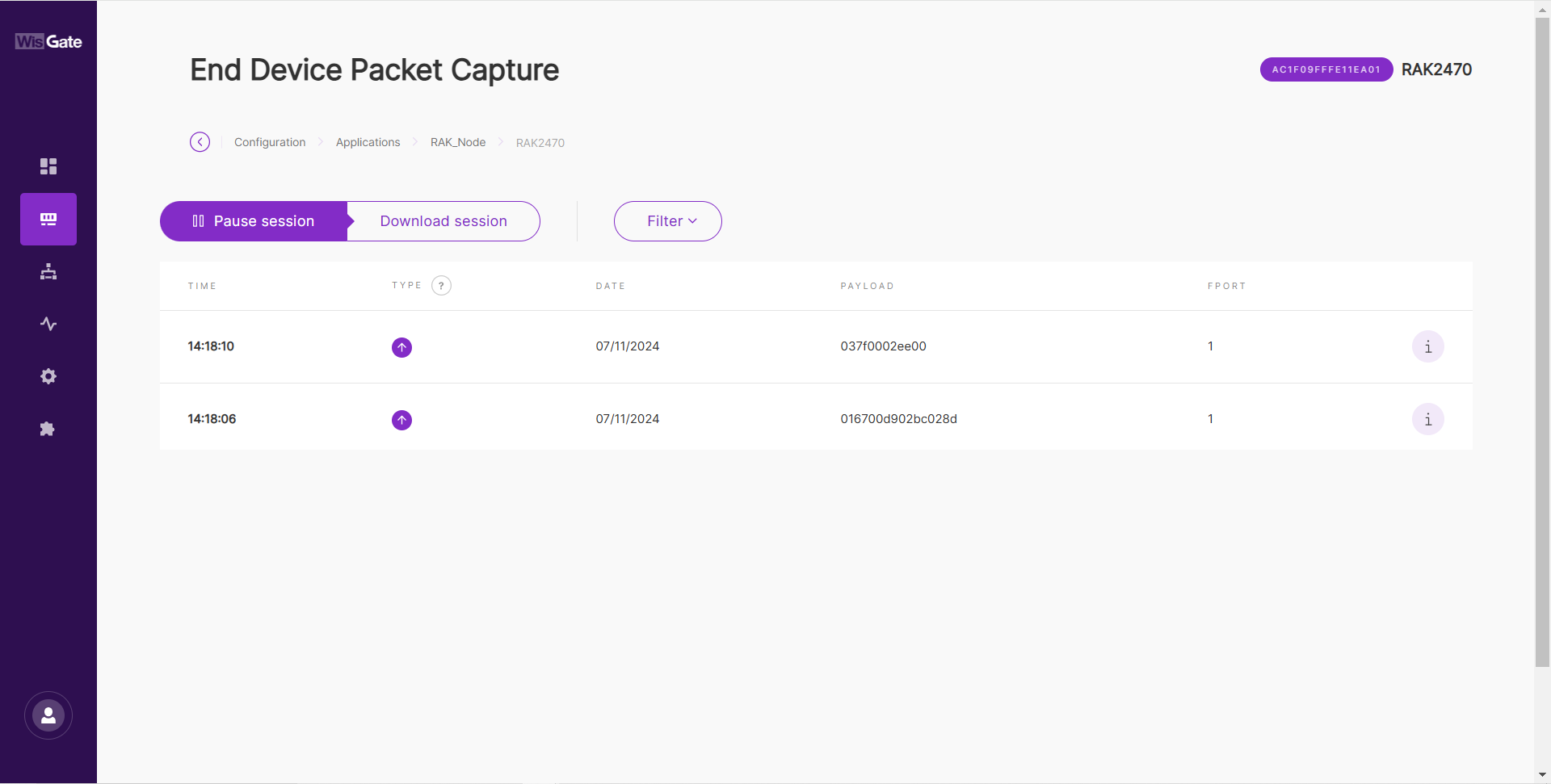 Figure 1: Uplink data
The Things Network (TTN)
Gateway Configuration
RAK gateways can connect to The Things Stack (TTN v3) using the following methods:
Packet Forwarder (UDP)
To connect a gateway to TTN v3 using Packet Forwarder (UDP), see How to Connect RAK Gateways to TTN v3 via UDP.
Basics™ Station (LNS)
To connect a gateway to TTN v3 using Basics™ Station (LNS), see How to Connect RAK Gateways to TTN v3 Using Basics™ Station (LNS).
Basics™ Station (CUPS)
To connect a gateway to TTN v3 using Basics™ Station (CUPS), see How to Connect RAK Gateways to TTN v3 Using Basics™ Station (CUPS).
Bridge IO Configuration
You can create applications and automatically register node devices on the TTN network server through IO.Box. For detailed configuration steps, refer to The Things Stack (TTN v3) Integration.
- After the device is created successfully, you can view the added device in the TTN.
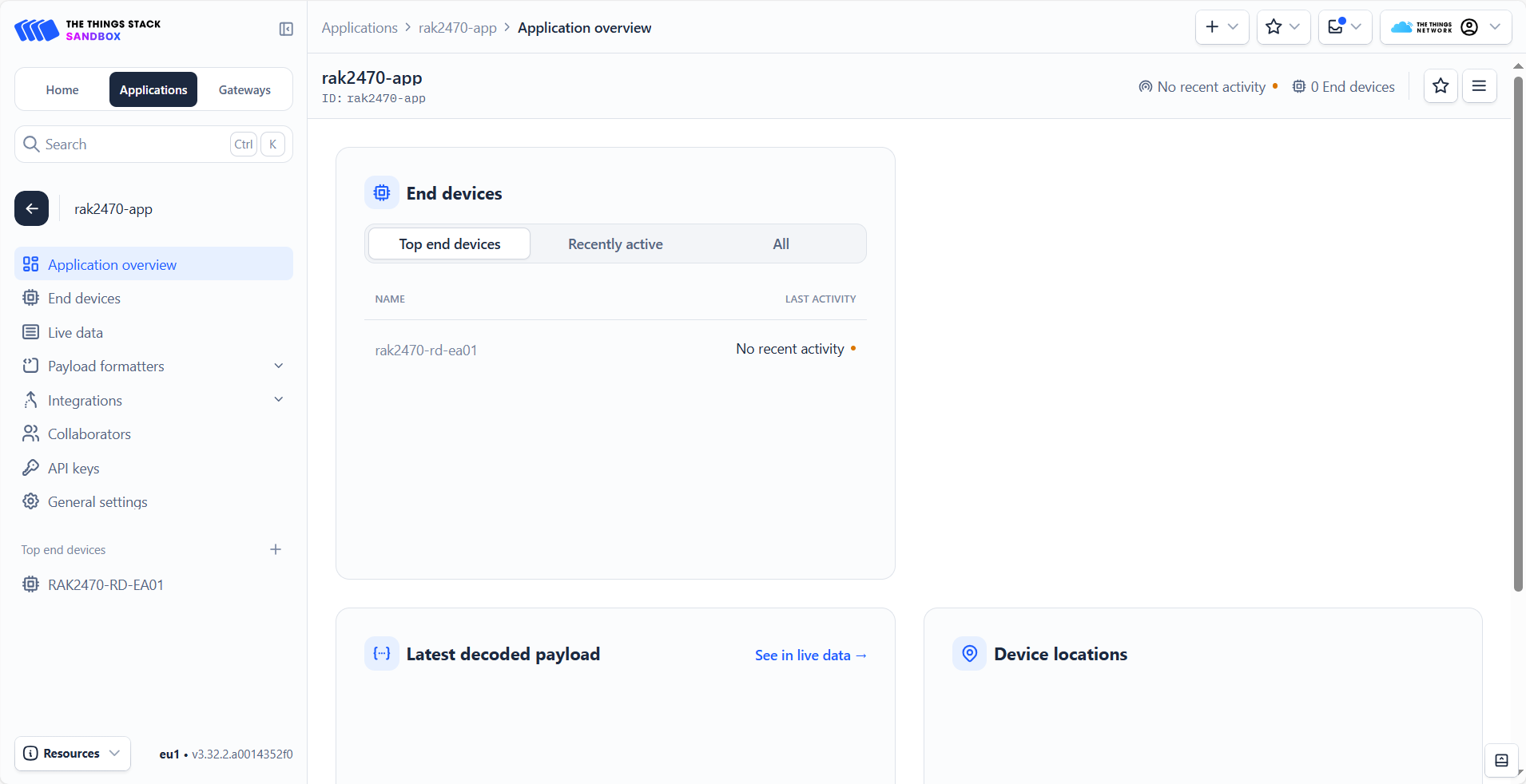 Figure 1: Added device in the TTN
- To activate the device, click Apply.
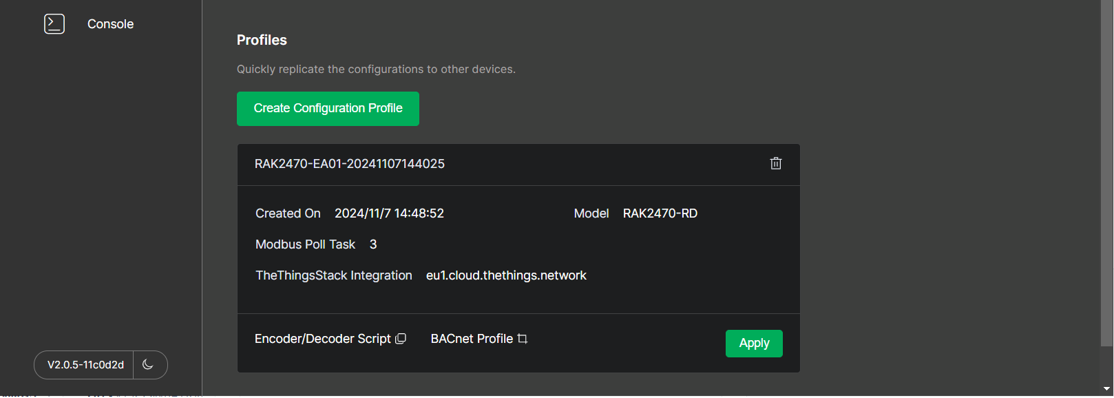 Figure 1: Active the device
- After a successful Apply, the device in the TTN is activated.
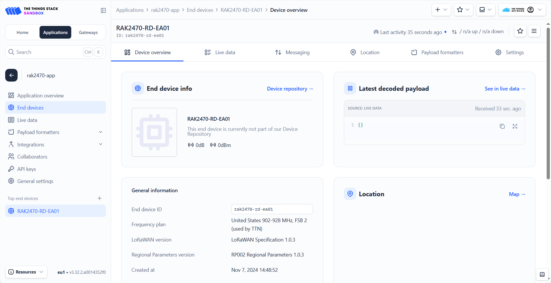 Figure 1: Device is onlineFigure 1: LoRaWAN status
Verify RS485 Uplink Data in TTN
The RAK2470 uses the same serial channel for IO.BOX configuration and RS485 sensor communication. Therefore, RS485-to-LoRaWAN® uplink forwarding starts only after the device exits Configuration Mode.
After the device joins the LoRaWAN® network successfully, it sends a verification uplink and keeps the configuration window open for a short period. If no further configuration is received, the device exits Configuration Mode, displays the exit warning, and enters Working Mode.
Figure 1: Exit WarningIn Working Mode, you can view the uplink data in TTN. The figure below shows the uplink data from the example sensor. For more details about the configuration-mode exit process, refer to Verify RS485 Uplink Data.
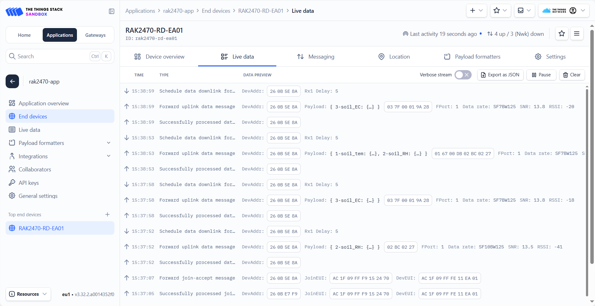 Figure 1: Data details
ChirpStack
This guide will show you how to connect the RAK2470 to a ChirpStack network server. In this tutorial, the ChirpStack v4 network server is used as an example.
Gateway configuration
A gateway can be connected to the ChirpStack v4 server using the following methods:
Packet Forwarder (UDP)
To connect a gateway to ChirpStack v4 using Packet Forwarder (UDP), see How to Connect RAK Gateways to Chirpstack v4 via UDP.
Packet forwarder (MQTT)
To connect a gateway to ChirpStack v4 using Packet Forwarder (MQTT), see How to Connect RAK Gateways to Chirpstack v4 via MQTT.
Basics™ Station (CUPS)
To connect a gateway to ChirpStack v4 using Basics™ Station (LNS), see How to Connect RAK Gateway to Chirpstack v4 Using Basics™ Station (LNS).
Bridge IO Configuration
You can create applications and automatically register node devices on the ChirpStack server through IO.Box. For detailed configuration steps, refer to ChirpStack v4 Integration.
- After the device is created successfully, you can view the added device in the ChirpStack.
 Figure 1: Added device in the ChirpStack
- To activate the device, click Apply.
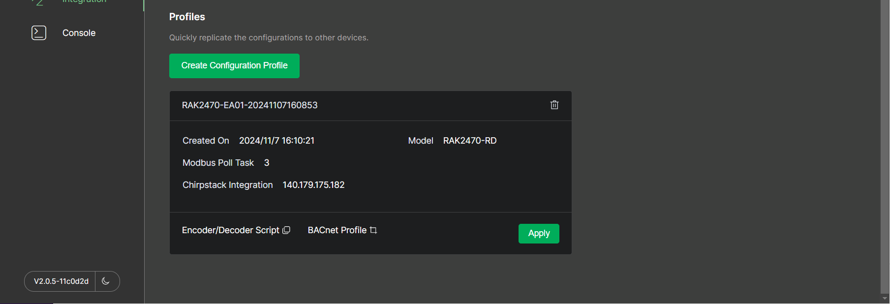 Figure 1: Active the device
- After a successful Apply, the device in the ChirpStack is activated.
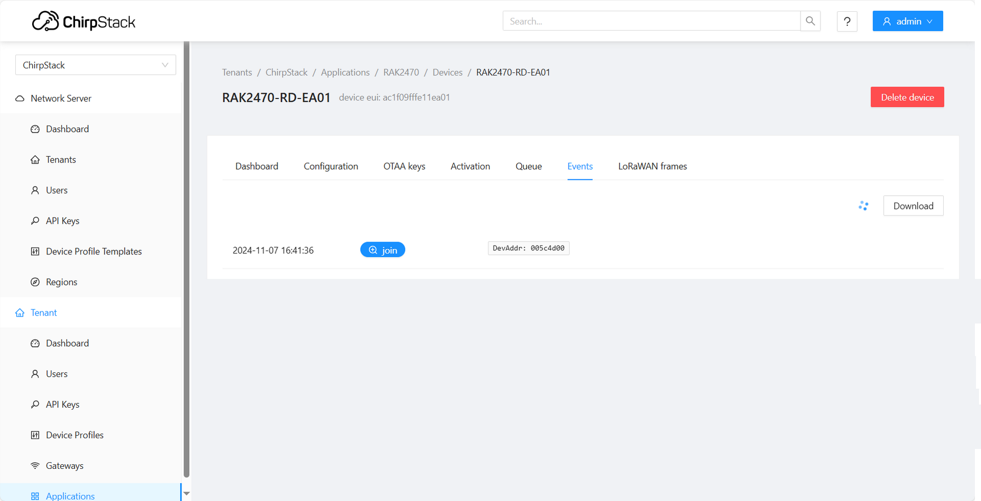 Figure 1: Active the deviceFigure 1: LoRaWAN status
Verify RS485 Uplink Data in ChirpStack
The RAK2470 uses the same serial channel for IO.BOX configuration and RS485 sensor communication. Therefore, RS485-to-LoRaWAN® uplink forwarding starts only after the device exits Configuration Mode.
After the device joins the LoRaWAN® network successfully, it sends a verification uplink and keeps the configuration window open for a short period. If no further configuration is received, the device exits Configuration Mode, displays the exit warning, and enters Working Mode.
Figure 1: Exit WarningIn Working Mode, you can view the uplink data in ChirpStack. The figure below shows the uplink data from the example sensor. For more details about the configuration-mode exit process, refer to Verify RS485 Uplink Data.
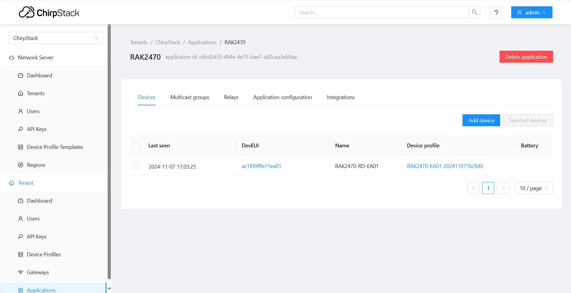 Figure 1: Device is online
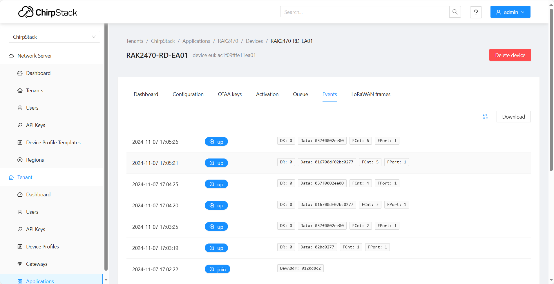 Figure 1: Data details
Remote Device Configuration via LoRaWAN Downlink
The Bridge IO device can be configured remotely through LoRaWAN downlink commands. This method allows you to modify parameters for the RS485 (Modbus), enabling control of connected peripheral devices.
The FPort for configuration commands must be set to 10.
General Command Format
All configuration downlinks follow this structure:
[Channel ID] [Command Code] [Payload]
Command Code Breakdown
The Command Code is a single hexadecimal byte where each bit group defines a specific action. Please refer to the following table for details.
| Bit Position | Function | Value & Meaning |
|---|---|---|
| Bit 7 | Get/Set | 0: Get (Read parameters)1: Set (Write parameters) |
| Bits 3-6 | Channel Type | 0: DI (Digital Input)1: DO (Digital Output)7: Modbus (RS485 interface) |
| Bit 2 | Enable/Disable | 0: Disable 1: Enable |
| Bits 0-1 | Parameter Mode | 00: Combined (Configure all parameters together)01: Individual (Configure parameters individually) |
Command Example
Combined Setting Example
A typical combined write command looks like this:
01 BC 01 03 00 00 00 01 04 3D CC CC CD 67 00 00 00 3C
-
01: Channel ID. Corresponds to the channel number shown in the device management interface. -
BC: Command Code. To understand it, convertBC(hex) to binary:1011 1100.-
Bit 7 =
1→ Set (Write command) -
Bits 3-6 =
0111(decimal 7) → Modbus channel -
Bit 2 =
1→ Enable the channel -
Bits 0-1 =
00→ Combined parameter mode
-
-
01 03 00 00 00 01 04 3D CC CC CD 67 00 00 00 3C: The Payload containing the specific configuration parameters for the channel.
Individual Setting Example
A typical individual write command looks like this:
01 BD 07 00 00 02 58
-
01: Channel ID. -
BD: Command Code. To understand it, convertBD(hex) to binary:1011 1101.-
Bit 7 =
1→ Set (Write command) -
Bits 3-6 =
0111(decimal 7) → Modbus channel -
Bit 2 =
1→ Enable the channel -
Bits 0-1 =
01→ Individual parameter mode
-
-
07 00 00 02 58: Payload. Contains the specific parameter being modified and its corresponding value.-
07→ Parameter ID (Interval) -
00 00 02 58→ Interval value = 600 seconds
-
Command Payload Specification
You can use LoRaWAN downlinks to remotely add a Modbus poll task or modify the parameters of an existing task.
Write Command Example: 01 BC 01 03 00 00 00 01 04 3D CC CC CD 67 00 00 00 3C
Command Structure Breakdown
-
01: Channel ID -
BC: Command Code (Indicates a Set/Write command for configuring an enabled Modbus channel in Combined Parameter Mode) -
Payload:
-
01: Device Address = 1 -
03: Function Code = 3 (Read Holding Register) -
00 00: Register Address = 0 -
00 01: Quantity = 1 -
04: Data Type = INT16_BE - Integer (16bit) - Big-Endian -
3D CC CC CD: Scale Factor = 0.1 -
67: Sensor Type = 0x67 (103, Temperature) -
00 00 00 3C: Interval = 60 seconds (0x3C)
-
You can enter the read command 01 38 in the LoRaWAN Downlink server to retrieve the current parameter configuration payload.
LoRaWAN Downlink Server Configuration
Before configuring LoRaWAN downlinks, ensure that your Bridge IO is connected to a LoRa Network Server and is actively communicating on the network.
This example demonstrates how to remotely change the data type of the Modbus Poll Task for Channel ID 1 to UINT16_BE - Unsigned Integer (16bit) - Big-Endian.
Built-in Network Server
-
Log in to your gateway's web management interface.
-
Go to LoRa > Applications > End devices > Downlink.
-
On the Downlink page, configure the following and click Send to transmit the command.
-
Frame Confirmation: Enable.
-
FPort: Set to
10. -
HEX Bytes: Enter the hexadecimal configuration command without any spaces.
-
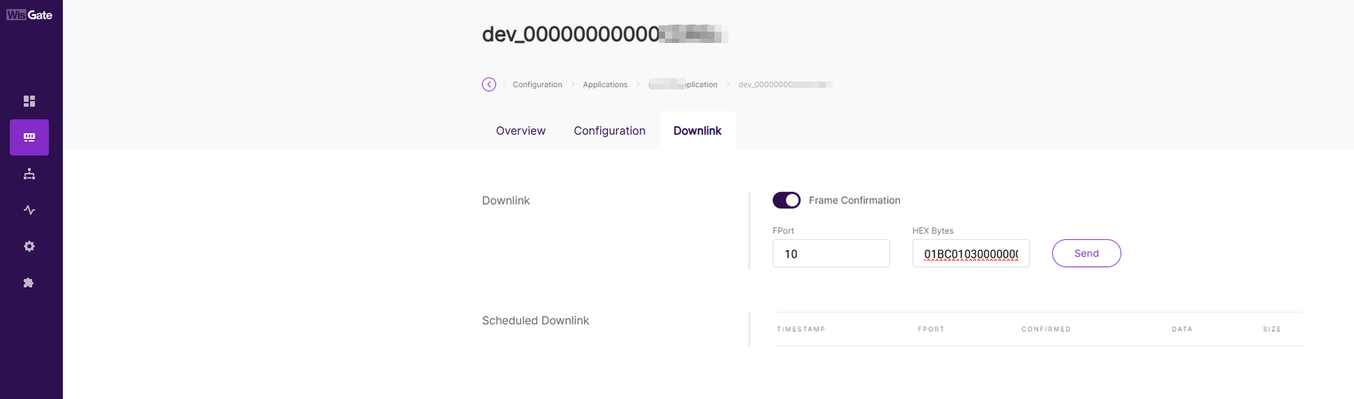 Figure 1: LoRaWAN Downlink built in
- Verify that the data type for RS485 Channel ID 1 has been updated to
UINT16_BE.
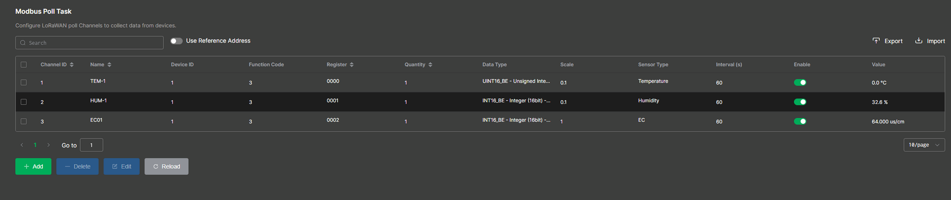 Figure 1: Modbus Poll Task
The Things Network (TTN)
-
Log in to the TTN Console.
-
Select your Application and the target End Device.
-
Navigate to the Messaging > Schedule downlink tab, configure the parameters, and click Schedule downlink to send the command.
-
Insert Mode:
Replace downlink queue -
FPort:
10 -
Payload type:
Bytes -
Payload: Enter the hexadecimal configuration command.
-
Confirmed downlink: ✔ Check this box.
-
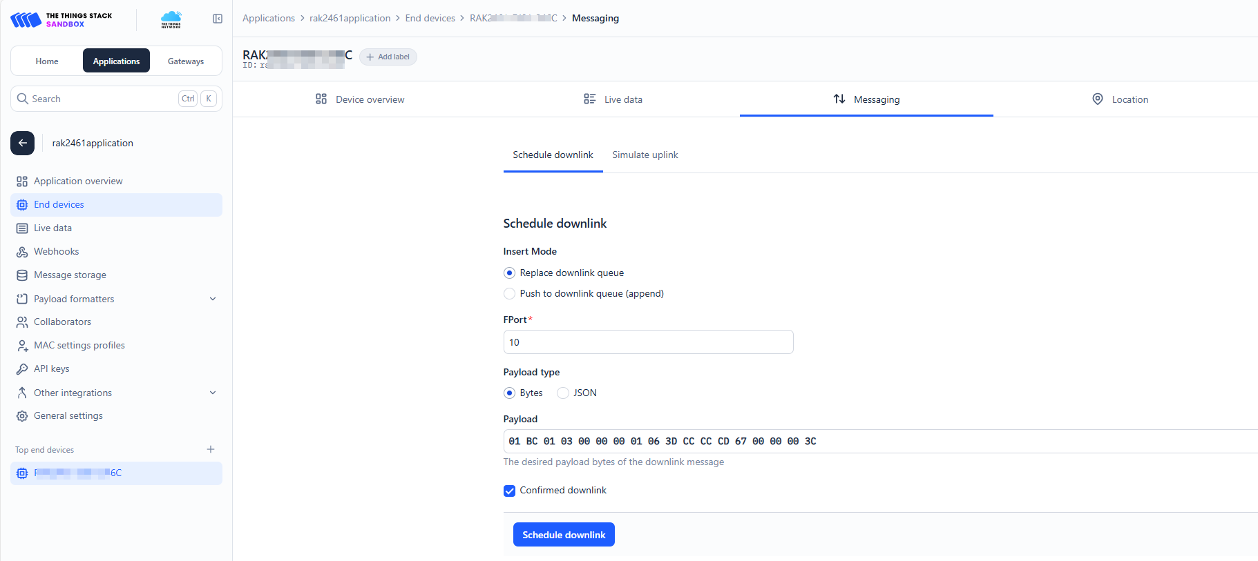 Figure 1: LoRaWAN Downlink TTN
- Verify the change in your device's RS485 configuration for Channel ID 1.
Figure 1: Modbus Poll Task- Check the Live data tab in the TTN server to view the acknowledgment message returned by the device.
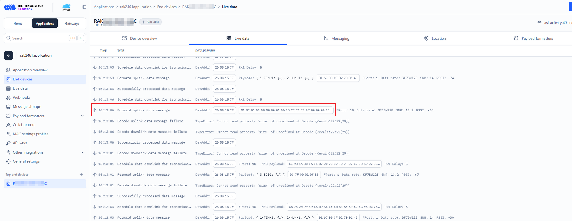 Figure 1: TTN confirmed
ChirpStack
-
Log in to the ChirpStack Network Server.
<IP address of ChirpStack>:8080 -
In the left navigation pane, go to Applications, select your target application, and then choose the specific end device.
-
Navigate to the device's Queue tab, configure the downlink parameters, and click Enqueue to send the command.
-
Confirmed: Enable.
-
FPort: Set to
10. -
HEX: Enter the hexadecimal configuration command.
-
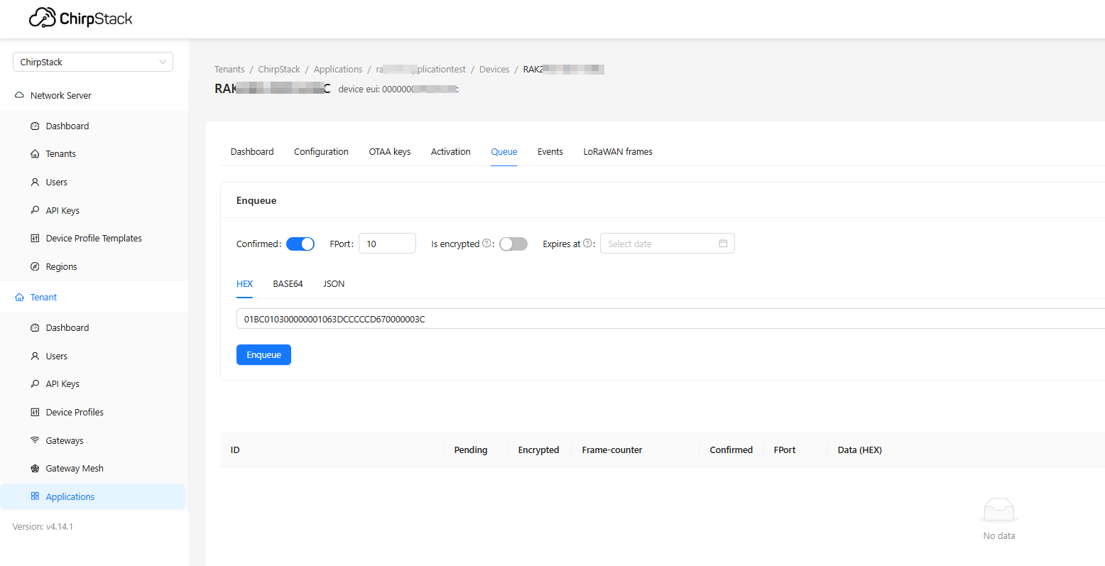 Figure 1: LoRaWAN Downlink ChirpStack
- Verify in your device's RS485 configuration that the data type for Channel ID 1 has been updated to
UINT16_BE.
Figure 1: Modbus Poll Task- Check the Events tab in the ChirpStack server to view the acknowledgment message returned by the device.
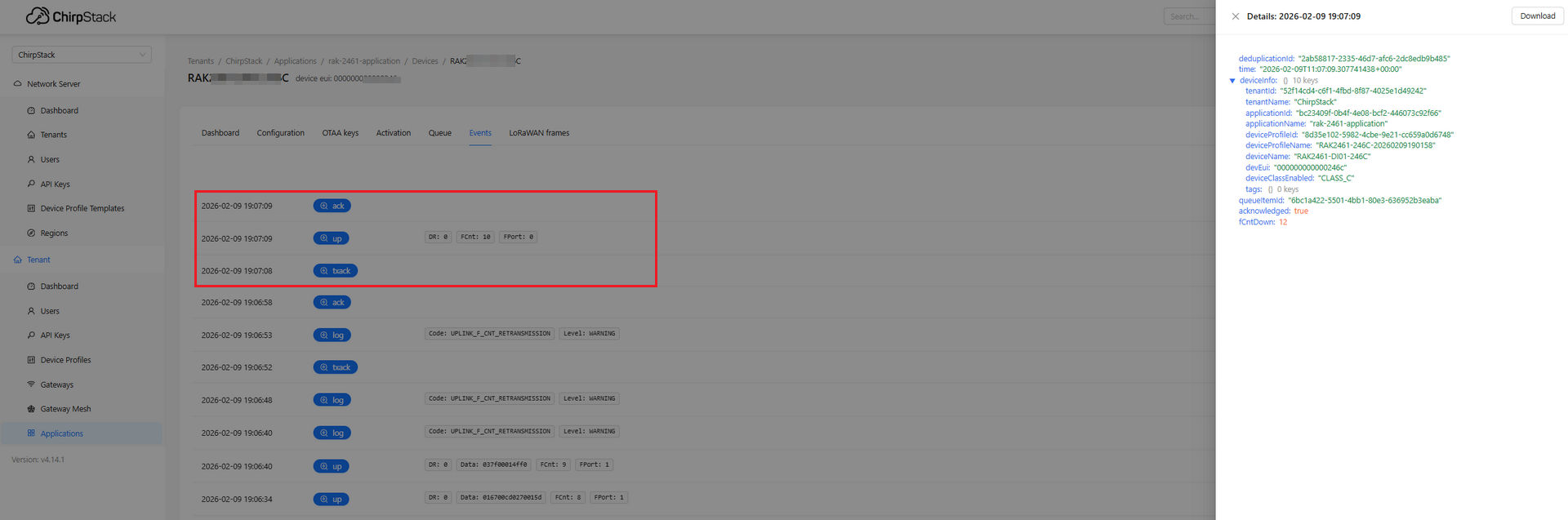 Figure 1: ChirpStack confirmed
Transparent Transmission
Transparent Transmission allows Bridge IO devices to transmit raw RS485 data over LoRaWAN without parsing, thereby preserving protocol integrity (e.g., Modbus RTU) while reducing latency and enhancing integration flexibility.
It supports two modes: Polling Transparent Mode for active polling and Passive Transparent Mode for direct bidirectional forwarding, both of which are configurable in the RS485 Interface.
Polling Transparent Mode
Polling Transparent Mode allows the device to function as a Modbus Master, actively polling RS485 devices based on configured tasks and forwarding the raw Modbus RTU response data to the LoRaWAN server without parsing.
Configure RS485 Interface
To configure the RS485 interface, follow these steps:
-
From the main menu, navigate to RS485 and set Transmission Mode to Polling Transparent Mode.
Max Payload Size is automatically determined by the region and DataRate settings, and does not require manual configuration.
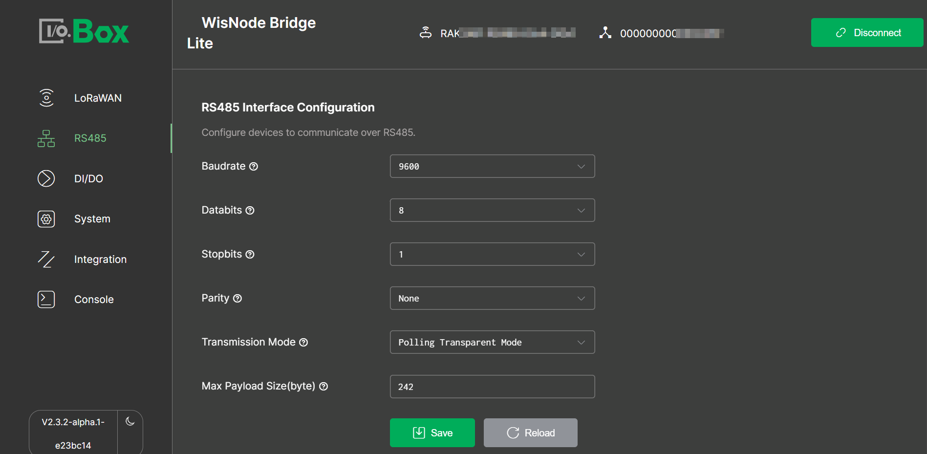 Figure 1: Polling Transparent
- Create a Temperature polling task and click Check to perform automatic validation.
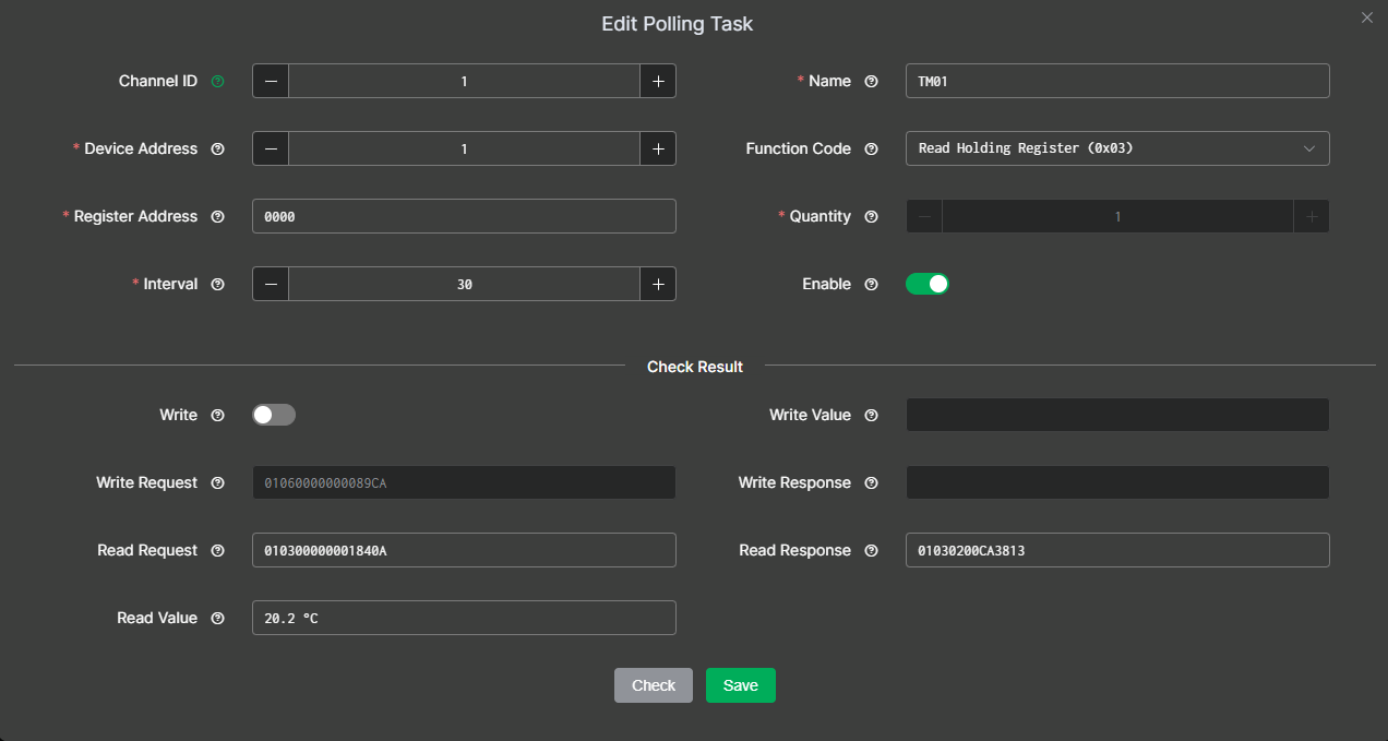 Figure 1: Polling Temperature
If the returned values are correct, Save the task.
- Create Moisture and EC polling tasks and perform automatic validation in the same way.
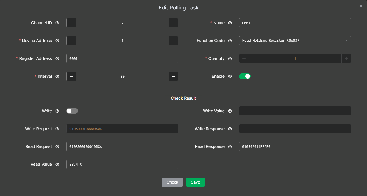 Figure 1: Polling Humidity
 Figure 1: Polling EC
RS485 Data Interaction
Uplink
You can log in to the following platforms to view raw RS485/Modbus data without parsing.
-
Built-in Network Server
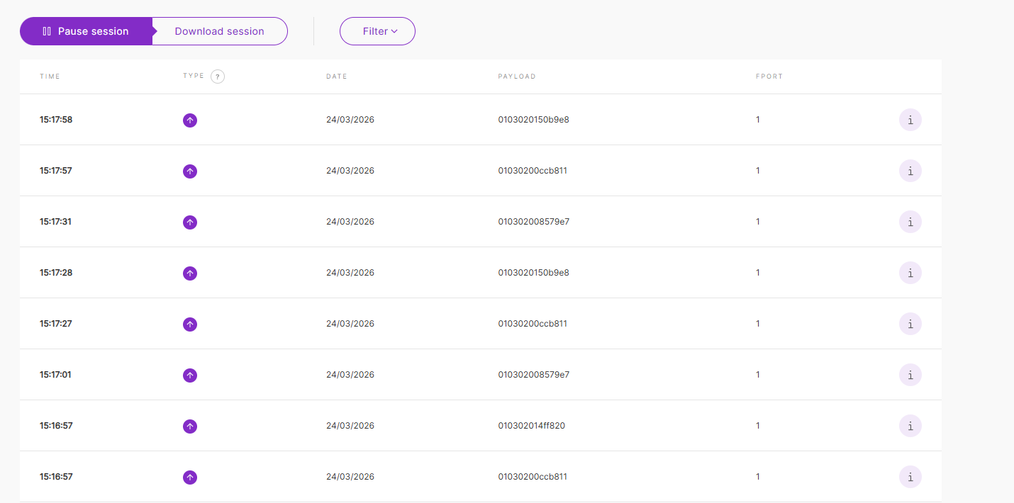 Figure 1: built in Transparent
 -
The Things Network (TTN)
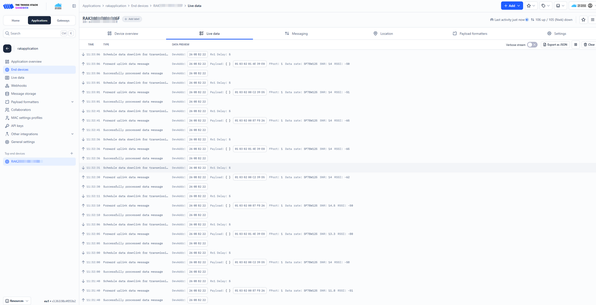 Figure 1: TTN Transparent
 -
ChirpStack
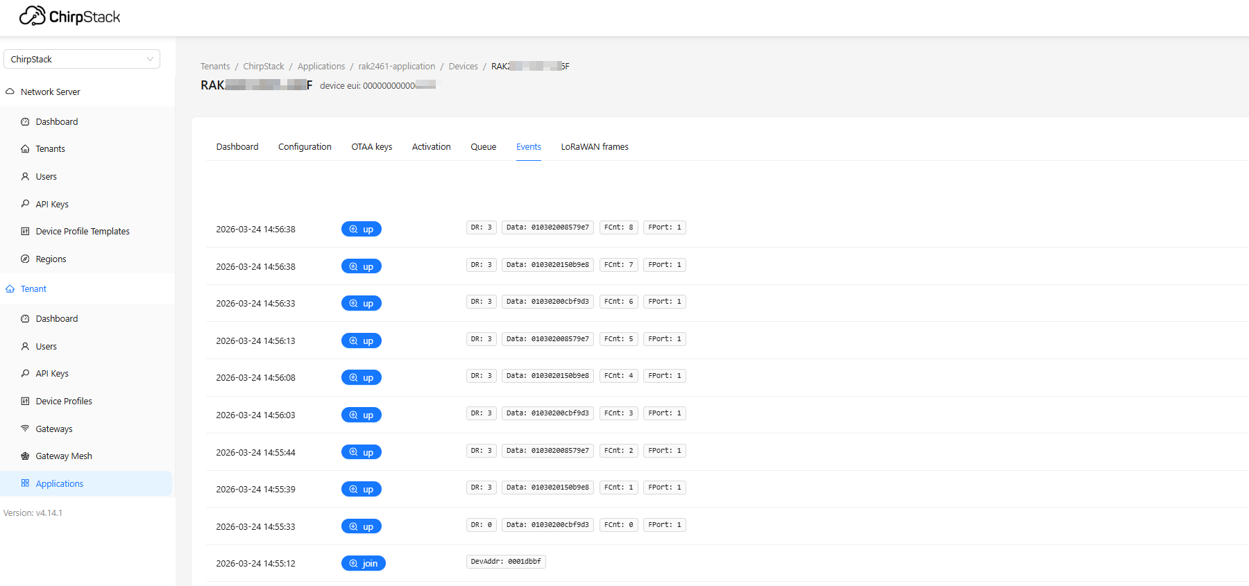 Figure 1: ChirpStack Transparent
Downlink
To query RS485 devices via downlink, refer to the device specification (e.g., RK520-02 Soil Sensor) when constructing the query command.
-
The Modbus CRC should be excluded from the command payload, as it will be automatically appended by the Bridge IO device during transmission.
-
In Polling Transparent Mode, the FPort for configuration commands must be set to 130.
-
Built-in Network Server
Enter
010300000001in the Downlink Configuration page.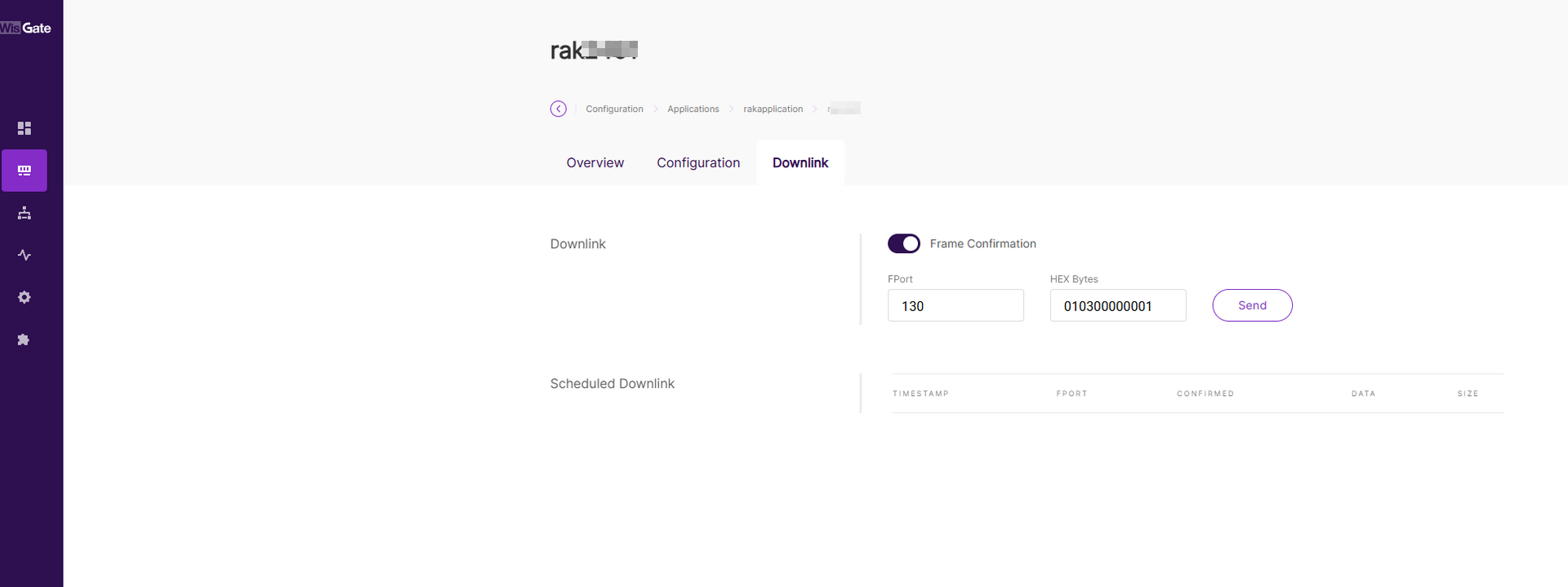 Figure 1: built in Transparent1
the returned data will be raw RS485 transparent data.
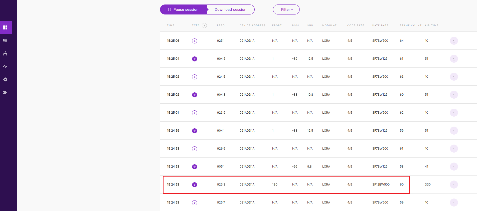 Figure 1: built in Transparent2
 -
The Things Network (TTN)
Enter
010300000001in the Schedule Downlink payload field.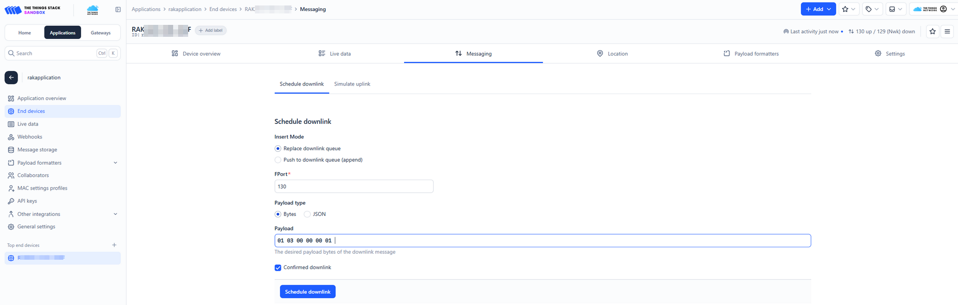 Figure 1: TTN Transparent1
the returned data will be raw RS485 transparent data.
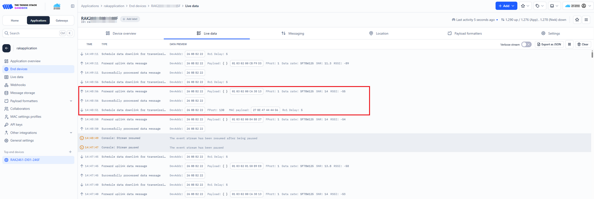 Figure 1: TTN Transparent2
 -
ChirpStack
Enter
010300000001in the Queue page.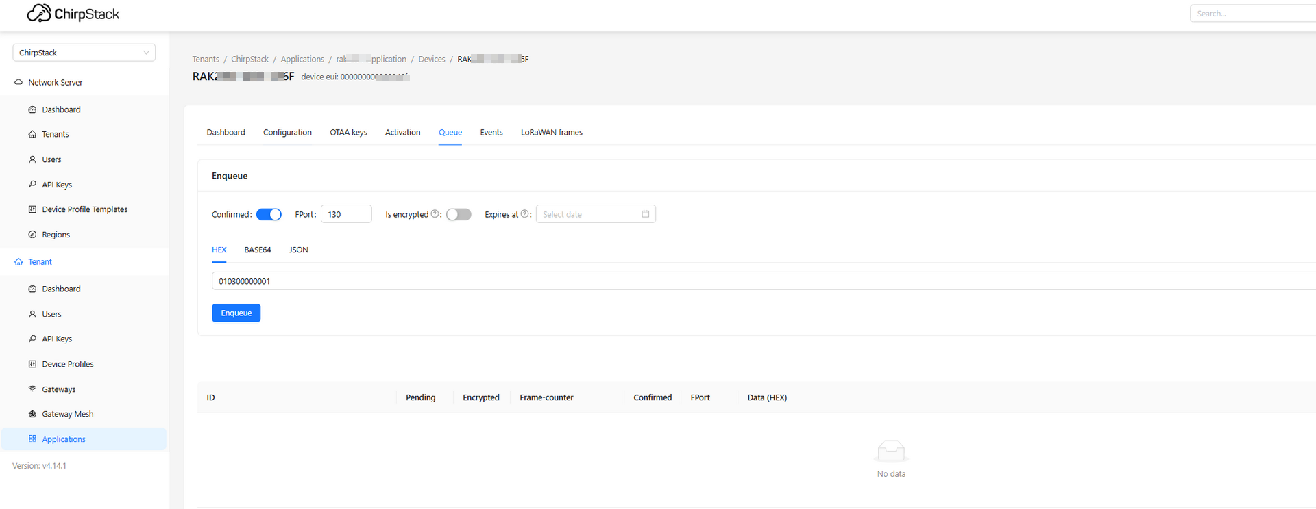 Figure 1: ChirpStack Transparent1
the returned data will be raw RS485 transparent data.
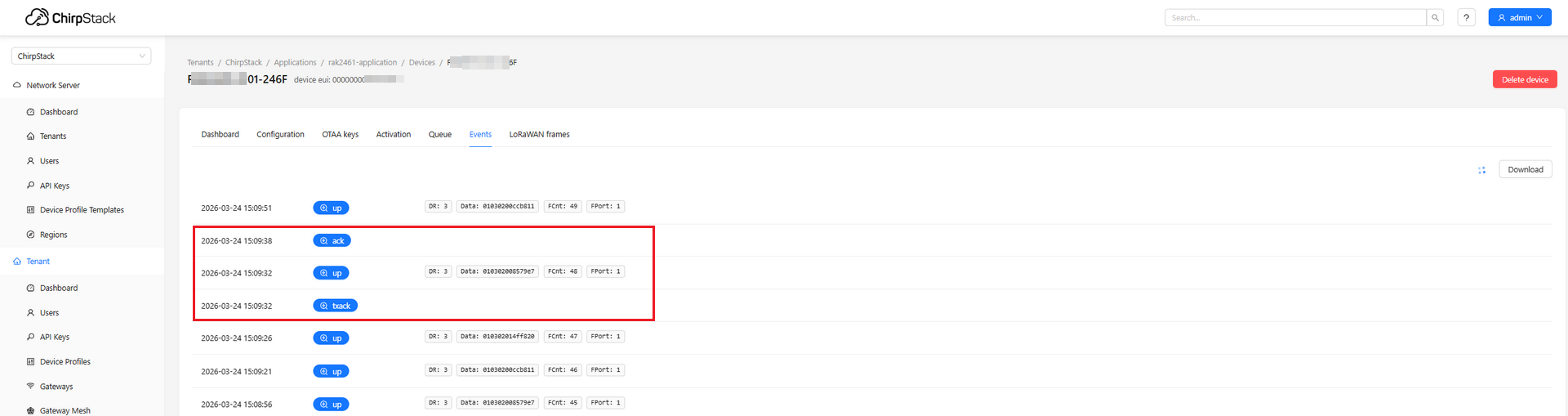 Figure 1: ChirpStack Transparent2
 -
Console interface
You can see in the Console interface that the Bridge IO has received the downlink command.
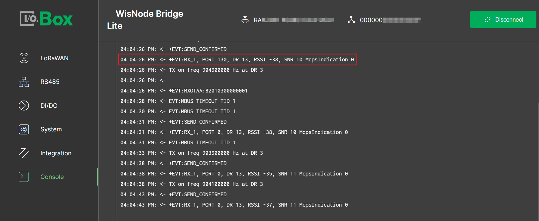 Figure 1: Console interface1
Passive Transparent Mode
Passive Transparent Mode establishes a fully transparent bridge between RS485 devices and the LoRaWAN server. In this mode, the device passively receives RS485 data and forwards it unchanged, without the need for Modbus polling, parsing, or task configuration.
Configure RS485 Interface
To configure the RS485 interface, apply the following settings:
- From the main menu, navigate to RS485 and set Transmission Mode to Passive Transparent Mode.
The Max Payload Size is automatically determined by the region and DataRate settings, and does not require manual configuration.
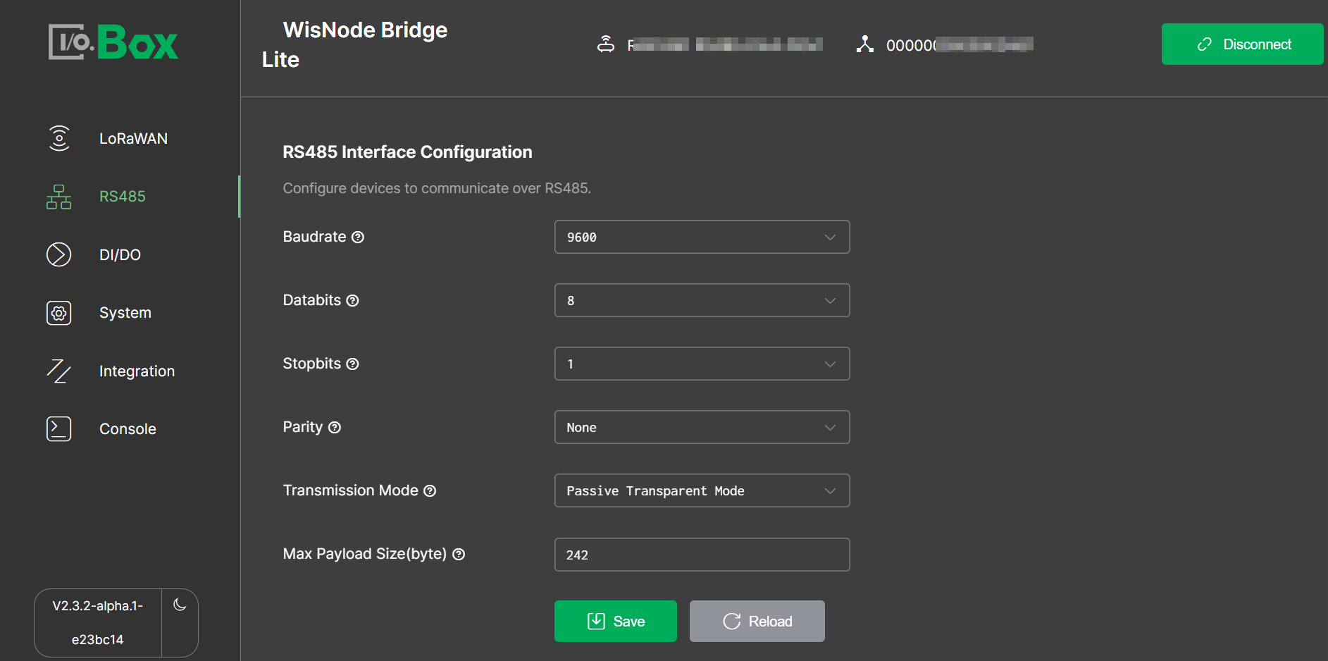 Figure 1: Passive Transparent
RS485 Data Interaction
You can log in to the Built-in Network Server, The Things Network (TTN), or ChirpStack to view both uplink and downlink data as raw RS485 data, without the need for parsing.
To send a downlink command, refer to the RS485 device specification. You can verify the sent command in the Bridge IO interface, and confirm its receipt in the Console.
In Passive Transparent Mode, the FPort for configuration commands must be set to 131.
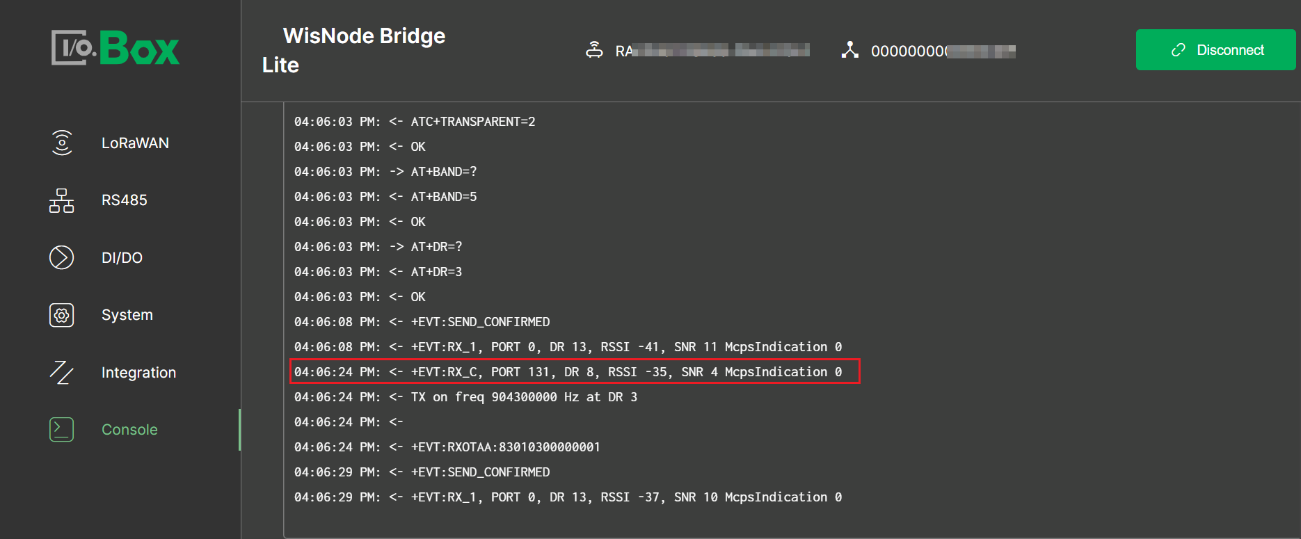 Figure 1: Console interface2