RS485 Configuration
RS485 is a robust serial communication interface widely used in industrial environments for long-distance, noise-resistant data transmission. In IO.Box, it is used to connect Modbus RTU slave devices (such as power meters, sensors, and PLC I/O modules) for periodic data collection and remote control through polling tasks.
RS485 Interface Configuration
RS485 interface configuration defines the physical-layer serial parameters used between IO.Box and a Modbus RTU device. In the RS485 Interface Configuration menu, you can configure these parameters to match the RS485 communication settings of the connected device. The configuration takes effect after clicking Save.
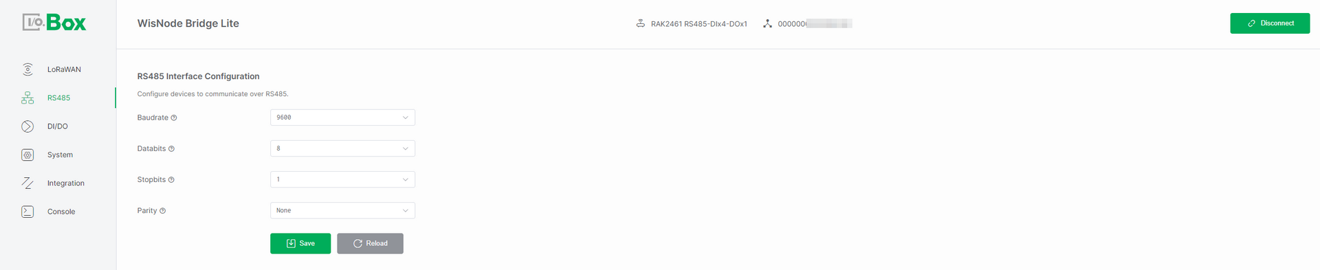 Figure 1: RS485 Interface configuration
-
Baudrate: The communication speed on the RS485 bus, measured in bits per second (bps). Select a baudrate that matches the speed required by your connected device.
-
Databits: The number of data bits in each character. Choose either 7 or 8 bits based on the protocol requirements specified by your device.
-
Stopbits: The number of bits that signal the end of a character frame. Configure this as 1 or 2 stop bits, depending on your device's data transmission protocol.
-
Parity: An error-checking method for serial communication. Select the parity setting that matches your device's requirements from the available options:
-
None (no parity check)
-
Even (even parity check)
-
Odd (odd parity check)
-
-
Transmission Mode: Defines how RS485 data is processed and transmitted between the device and the LoRaWAN network, allowing users to choose between parsed communication or raw transparent data transfer.
-
Parsing Mode: Converts RS485/Modbus data into structured LoRaWAN payloads through protocol parsing and formatting before transmission.
-
Polling Transparent Mode: Actively polls RS485 devices as a Modbus master and forwards the raw response data to LoRaWAN without any parsing or modification.
-
Passive Transparent Mode: The device passively receives data from RS485 devices and forwards it unchanged to the LoRaWAN network, without Modbus polling or task configuration.
-
-
Max Payload Size (byte): Defines the maximum LoRaWAN payload size (fixed and not user-configurable), which is determined by the region and DataRate settings. Data exceeding this limit is discarded.
NOTEThis parameter is only applicable when Transmission Mode is set to Polling Transparent Mode or Passive Transparent Mode.
Modbus Poll Task
The Modbus Poll Task configuration is used to manage Modbus communication. Once enabled, IO.Box can automatically read sensor data or write control commands, making it suitable for industrial automation, data acquisition, and device monitoring scenarios.
The Modbus Poll Task is available only when Transmission Mode is set to Parsing Mode or Polling Transparent Mode.
Add Modbus Poll Task
In the Modbus Poll Task menu, click + Add to create a polling task. Configure the parameters according to the connected device datasheet or manual.
The configuration fields vary depending on the Use Reference Address setting. When enabled, use the reference address format. When disabled, use the standard Modbus address format. Then click Save to activate the task.
Use Reference Address Enabled
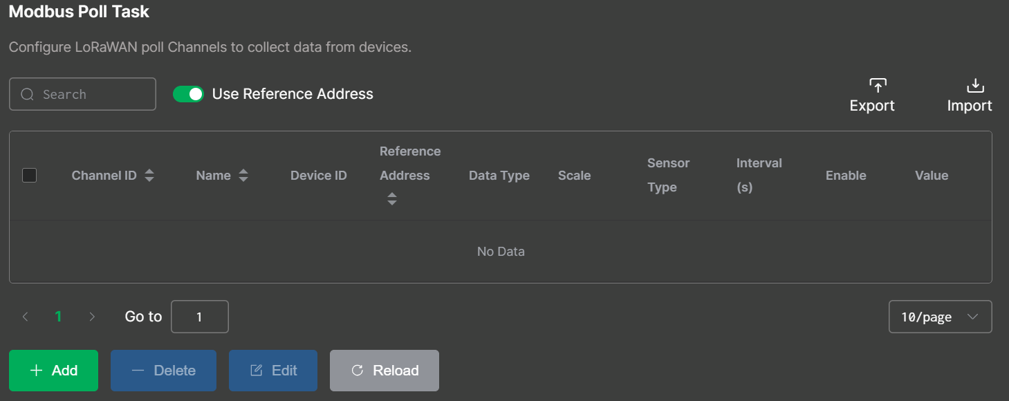 Figure 1: Use Reference Address Enabled
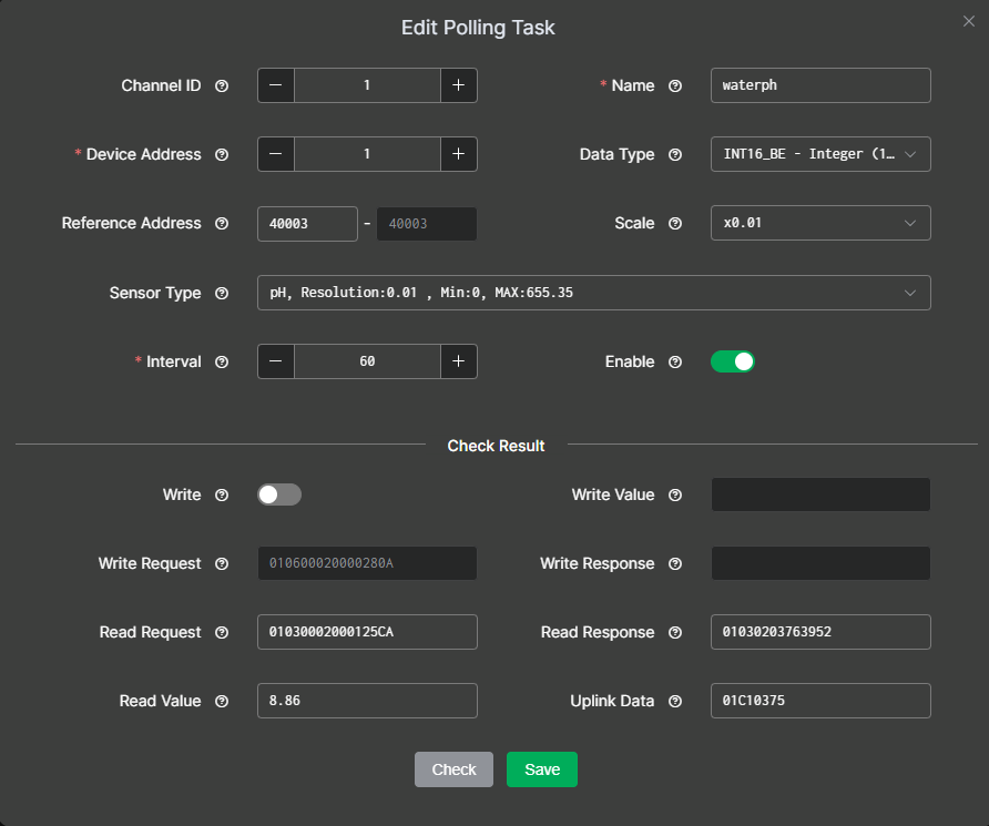 Figure 1: Poll Task Configuration1
Use Reference Address Disabled
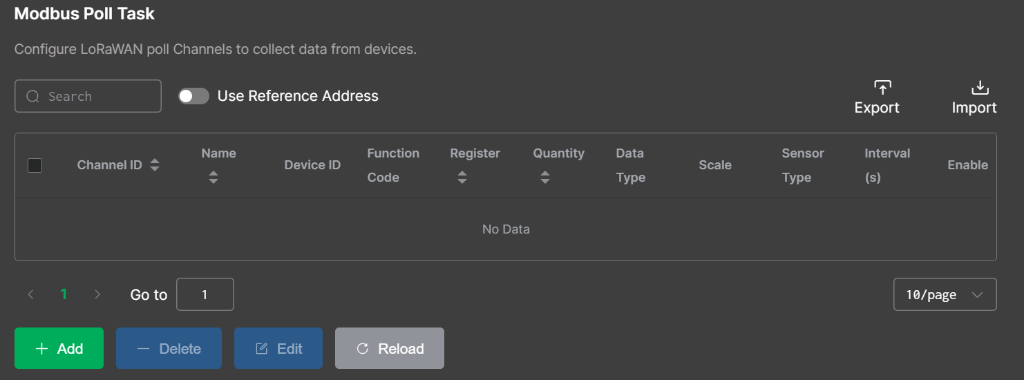 Figure 1: Use Reference Address Disabled
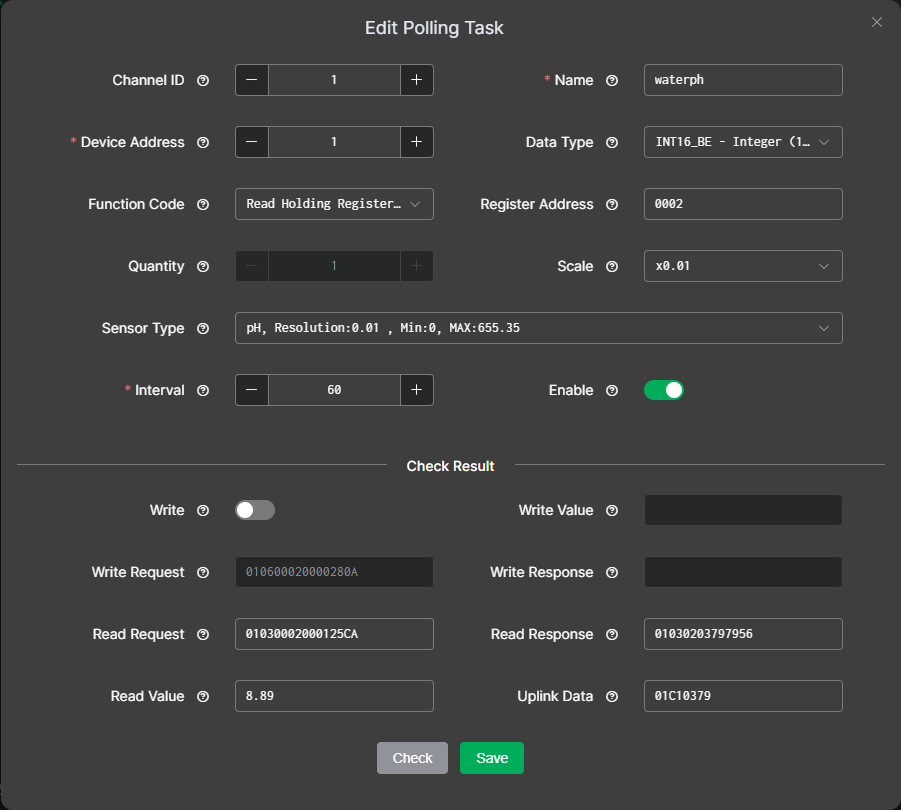 Figure 1: Poll Task Configuration2
After selecting the appropriate configuration method, configure the polling task parameters as described below. The following descriptions use Use Reference Address disabled as an example.
-
Channel ID: Manually assigned by the user to distinguish different data streams or communication channels. This ID is included in the device’s uplink data to indicate the task.
-
Name: Custom name. Length: 4–15.
-
Device Address: The unique address of the connected device on the RS485 bus, obtained from the device manual. If the manual provides the value in hexadecimal, convert it to decimal before entering. Range: 1–254.
-
Function Code: Specifies the task's Modbus operation type (read or write), obtained from the device manual. Common function codes:
-
Read Holding Register (0x03): Read/write configurable parameters (set points, thresholds).
-
Read Input Register (0x04): Read real-time measurements (sensor readings), read-only.
-
Read Coil (0x01): Read digital output states (relay/switch), readable and writable.
-
Read Discrete Input (0x02): Read digital input states (switch/alarm), read-only.
NOTEFunction codes 0x01 and 0x02 are available only when Data Type is set to Bit Values or Modbus ADU.
-
-
Reference Address
IO.Box supports two register addressing modes: Register Offset mode and Reference Address mode. The meaning of the Reference Address field depends on whether Use Reference Address is enabled.
By default, Use Reference Address is disabled. In this mode, the Reference Address field represents the Modbus 0-based register offset and must be entered in hexadecimal format, such as 0009.
If the device manual uses PLC/SCADA reference addresses, such as 40010, calculate the decimal offset first, then convert it to hexadecimal. For Holding Registers, the relationship is:
Reference Address = 40001 + Register Offset (decimal)Device manual address: 40010
Register Offset (decimal) = 40010 - 40001 = 9
Register Offset (hex) = 0009When Use Reference Address is enabled, the Reference Address field represents the PLC/SCADA reference address. In this mode, enter the address exactly as shown in the device manual, such as
40010. IO.Box will automatically convert the reference address to the corresponding Modbus 0-based register offset internally.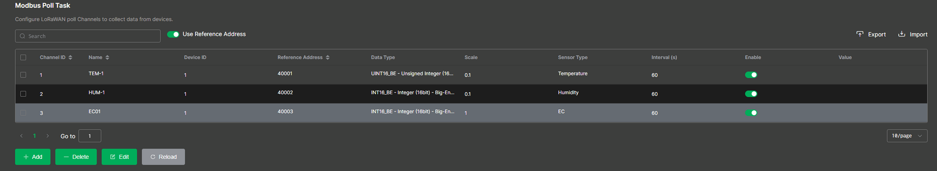 Figure 1: Poll Task configuration2
 -
Quantity: The number of registers or coils to read or write, determined by the selected Data Type. Refer to Table 1 for details.
-
Data Type: Defines how IO.Box parses the Modbus response payload into a usable value. This setting is configurable only when the Transmission Mode is set to Parsing Mode.
The value corresponds to the selected registers or coils' Quantity. Refer to Table 1 below for the specific mapping.
Table 1. Data Type vs. Quantity Correspondence Table
This table follows the common Modbus convention: one register = 16 bits (2 bytes). Always confirm with your device manual if it uses special packing.
Data Type Data Size Quantity (Registers) Notes INT16_BE 16-bit 1 Integer 16bit Big Endian UINT16_BE 16-bit 1 Unsigned Integer 16bit Big Endian INT16_LE 16-bit 1 Integer 16bit Little Endian UINT16_LE 16-bit 1 Unsigned Integer 16bit Little Endian INT32_BE (ABCD) 32-bit 2 Signed Integer 32bit Big Endian UINT32_BE (ABCD) 32-bit 2 Unsigned Integer 32bit Big Endian INT32 (CDAB) 32-bit 2 Signed Integer 32bit UINT32 (CDAB) 32-bit 2 Unsigned Integer 32bit INT32_LE (DCBA) 32-bit 2 Signed Integer 32bit Little Endian UINT32_LE (DCBA) 32-bit 2 Unsigned Integer 32bit Little Endian Float (ABCD) 32-bit 2 Big Endian Float (CDAB) 32-bit 2 Mixed endian Float (DCBA) 32-bit 2 Little Endian Bit Values varies Manually configurable Register or byte parsed as bit level fields implementation dependent Modbus ADU varies Manually configurable Raw frame parsing quantity depends on what you need to capture -
Scale: Used to scale raw Modbus response data to the desired units (e.g., set to ×1000 to convert kilograms to grams), and is configurable only when Transmission Mode is set to Parsing Mode.
-
Sensor Type: Selects the unit or category matching the slave device output for correct interpretation and is configurable only when Transmission Mode is set to Parsing Mode.
-
Interval: The frequency at which the device sends Modbus requests (polling period). Range: 5 to 86400 seconds.
-
Enable: Enable or disable the task. When disabled, IO.Box will not collect data or write values for this task.
Check Result
After you finish editing a poll task, click Check to validate whether:
-
The configuration parameters are correct.
-
The device can communicate successfully, and the response can be parsed into the expected value and uplink payload format.
If there are no issues during the check, click Save to save the configuration.
-
Write: Enables writing to device registers or coils. Configurable when Function Code is Read Holding Register (0x03) or Read Coil (0x01).
-
Write/Read Request: Displays the Modbus command generated from the polling task configuration, based on the selected settings, which is used to communicate with the Modbus device.
-
Write/Read Response: The response returned by the slave for the request, indicates whether the operation succeeded and contains returned data.
-
Write Value: The value written to the specified register or coil.
-
Read Value: The parsed value extracted from the response according to the above configuration.
-
Uplink Data: The formatted payload that IO.Box sends to the server based on the task configuration. Available only when Transmission Mode is set to Parsing Mode.
Edit Modbus Poll Task
To modify an existing Poll Task, follow these steps:
-
Go to the Modbus Poll Task menu.
-
Select the target Poll Task from the list and click Edit.
-
Update the required fields, such as Interval, Register Address, Quantity, and Data Type.
-
Click Save to apply the changes.
Import/Export Poll Task
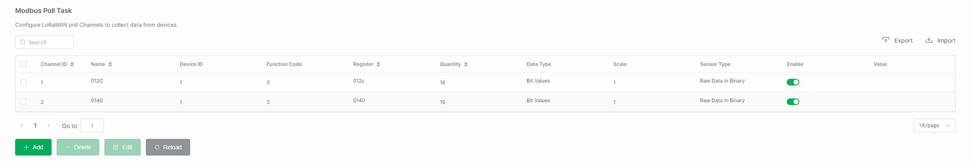 Figure 1: Import or Export Poll Task
Import Poll Task
The Import function is used to quickly apply a set of predefined polling tasks to a device, without the need to create them manually one by one. Typical use cases include batch deployment and device replacement.
In the Modbus Poll Task menu, click Import, then select and upload the Modbus Poll Task template file you wish to import.
Export Poll Task
The Export function is used to back up the polling task configuration for later reuse. It is useful for scenarios like saving templates and version management.
In the Modbus Poll Task menu, click Export to download the currently configured Modbus Poll Task to a specified path.
Delete Modbus Poll Task
If you want to delete a polling task, go to the Modbus Poll Task menu, select the target Poll Task, click Delete, and then click OK to remove the task.
After deletion, the device will stop polling those registers, and the corresponding uplink data will no longer be generated for that Channel ID.