Configuration of Analog Input (AI) and Analog Output (AO) for IO.Box
The AI/AO interface includes Analog Input (AI) and Analog Output (AO) channels, which handle continuously varying analog signals. With proper configuration of the AI/AO interfaces, users can implement industrial process monitoring, environmental data acquisition, and closed-loop analog control.
Analog Input
Analog Input (AI) interfaces are designed to collect continuously varying signals from external sensors. Typical sources include temperature, pressure, liquid level, and current transmitters. These signals are converted into digital values for system processing and monitoring.
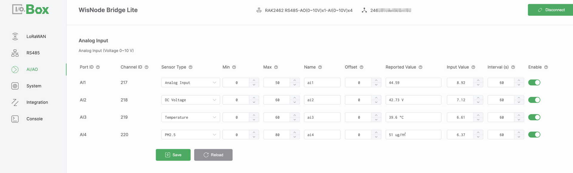 Figure 1: AI/AO tab1
Configuration Steps
-
Navigate to the AI/AO module and select the Analog Input menu.
-
Select the target Port ID and configure the following parameters.
-
Select a Sensor Type such as
Temperature. -
Set the Min and Max values based on the device specification datasheet.
-
Configure the Offset value if adjustment is required.
-
-
Set Enable to ON and click Save to apply the configuration.
-
Confirm that the Reported Value is displayed correctly and updates as expected.
NOTEIf the Reported Value does not match the expected result, refer to Analog Input Scaling Logic to verify the mapping formula.
Parameter Descriptions
-
Port ID: Port ID is a physical AI port identifier. It corresponds one-to-one with the Bridge I/O hardware interface. This is automatically assigned and cannot be modified.
-
Channel ID: Channel ID is a unique identifier assigned by the system. It is used internally for data identification processing and uplink reporting. This value is automatically assigned and cannot be modified.
-
Sensor Type: Defines the semantic type of the connected sensor. It determines how the value is interpreted and displayed in the system.
-
Min: Defines the engineering value corresponding to the lower bound of the input signal. This value is obtained from the device specification datasheet.
-
Max: Defines the engineering value corresponding to the upper bound of the input signal. This value is obtained from the device specification datasheet.
-
Name: User-defined name for the channel.
-
Offset: An adjustment value applied to correct the calculated result. It is typically used to compensate for sensor zero drift or installation deviation.
-
Reported Value: The final engineering value after min or max scaling and offset adjustment. It represents the actual physical quantity.
-
Input Value: The raw analog input value measured by the hardware. It represents the actual electrical signal such as current or voltage.
-
Enable: Enables or disables the AI channel. When disabled, the channel does not collect or report data.
Analog Input Scaling Logic
The AI interface supports two analog input specifications. These include voltage mode 0 – 10 V and current mode 4 – 20 mA. Each mode uses a specific linear scaling formula to convert the measured Input Value into an engineering value called the Reported Value.
-
Voltage mode (0 – 10 V):
Reported Value = (Input Value / 10) × (Max − Min) + Min + Offset -
Current mode (4 – 20 mA):
Reported Value = ((Input Value − 4) / 16) × (Max − Min) + Min + Offset
This document uses Voltage mode 0 – 10 V as an example.
Assuming Min = 0, Max = 50, Offset = 0, and an Input Value of 8.92 V. The system applies linear scaling to convert the input voltage into an engineering value: Reported Value = (8.92 / 10) × 50 ≈ 44.6.
Analog Output
Analog Output AO interfaces are used to generate analog control signals. These signals drive actuators such as control valves, variable speed motors, and other industrial equipment.
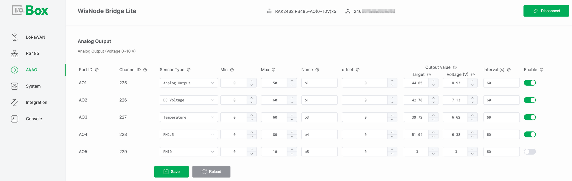 Figure 1: AI/AO tab2
Configuration Steps
-
Navigate to the AI/AO module and select the Analog Output menu.
-
Select the target Port ID and configure the following parameters.
-
Select a Sensor Type such as DC Voltage.
-
Set the Min and Max values based on the device specification datasheet.
-
Configure the Offset value if adjustment is required.
-
Set the Target Value and set Enable to ON.
-
-
Click Save and verify that the output signal matches the expected value. The output can be either Current mA or Voltage V.
NOTEIf the output signal does not match the expected result, refer to Analog Output Scaling Logic to verify the conversion formula.
Parameter Descriptions
-
Port ID: Port ID is a physical AO port identifier. It has a one-to-one mapping with the Bridge IO hardware interface. It is automatically assigned by the system and cannot be modified.
-
Channel ID: Channel ID is a unique identifier assigned by the system. It is used internally for data identification processing and uplink reporting. This value is automatically assigned and cannot be modified.
-
Sensor Type: Defines the semantic type of the configured output signal. It determines how the target value is interpreted and applied by the system.
-
Min: Defines the minimum engineering value of the output range. This value is obtained from the device specification datasheet.
-
Max: Defines the maximum engineering value of the output range. This value is obtained from the device specification datasheet.
-
Name: User-defined name for the output channel.
-
Offset: An adjustment value applied to correct the calculated result. It is typically used to compensate for system deviation or installation differences.
-
Target: User-defined target engineering value. This value represents the desired control level in engineering terms such as a valve opening of 75%. It is used as the reference input for AO output calculation.
-
Output Value: The calculated value derived from the configured target. It is used as the basis for generating the physical analog output signal.
-
Current (mA)/ Voltage (V): The real time physical analog signal generated by the AO port. This value represents the electrical form of the Output Value.
-
Current (mA) in 4 – 20 mA mode
-
Voltage (V) in 0 – 10 V mode
This value reflects the actual internal output of the device and can be measured directly at the AO interface.
-
-
Enable: Enables or disables the AO channel. When disabled, the channel does not output any signal.
Analog Output Scaling Logic
The AO interface converts the target engineering value into a physical analog output signal using linear scaling. The applied formula depends on the selected AO hardware output mode. The AO interface supports two analog output specifications.
-
Voltage mode (0 – 10 V):
Output Voltage (V) = (Target − Min) / (Max − Min) × 10. -
Current mode (4 – 20 mA):
Output Current (mA) = (Target − Min) / (Max − Min) × 16 + 4.
This document uses Voltage mode (0 – 10 V) as an example.
Assume Min is 0. Max is 50. Offset is 0. Target is 29. The system converts the target value into an analog voltage output.
Output Voltage = (29 / 50) × 10 ≈ 5.8 V