RAK7201 Quick Start Guide
Prerequisites
What do you need?
Before going through each and every step in the installation guide of the RAK7201 WisNode Button, make sure to prepare the necessary items listed below:
- RAK7201 WisNode Button 4K
- Micro USB cable
- Gateway in range
- Windows PC
What’s included in the package
- 1 pc WisNode Button 4K RAK7201
- 1 pc Micro USB cable
- 1 pc Sticker for attaching the button to flat surface
Product Configuration
Interfacing with the RAK7201 WisNode Button 4K
For you to be able to interface with the RAK7201 WisNode Button 4K with your Windows Machine, you need to download the RAK Serial Port Tool.
- Connect your RAK7201 WisNode Button 4K to your Windows Machine using the provided Micro USB cable.
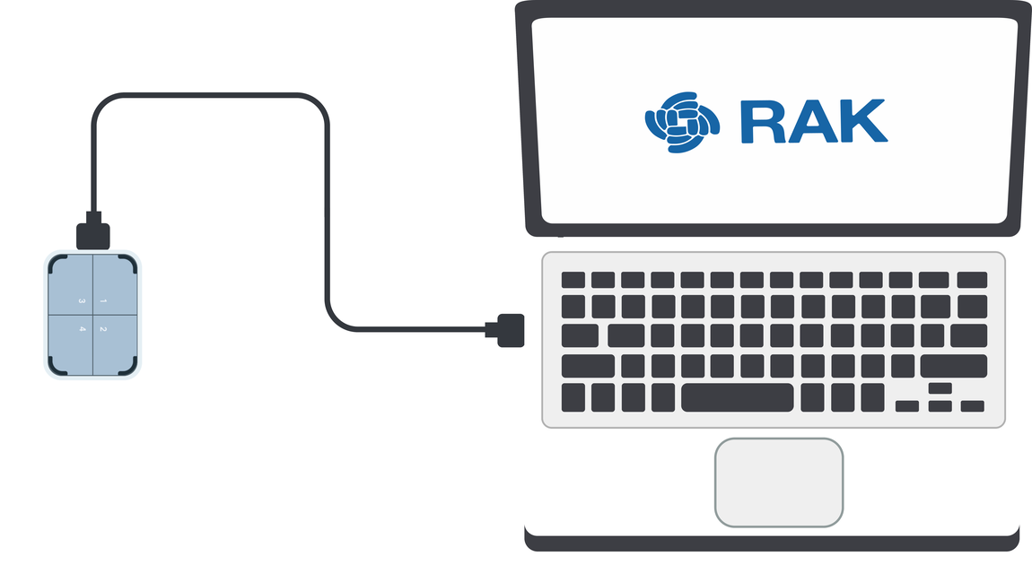 Figure 1: RAK7201 WisNode Button 4k to laptop connection
- Open the RAK Serial Port Tool.
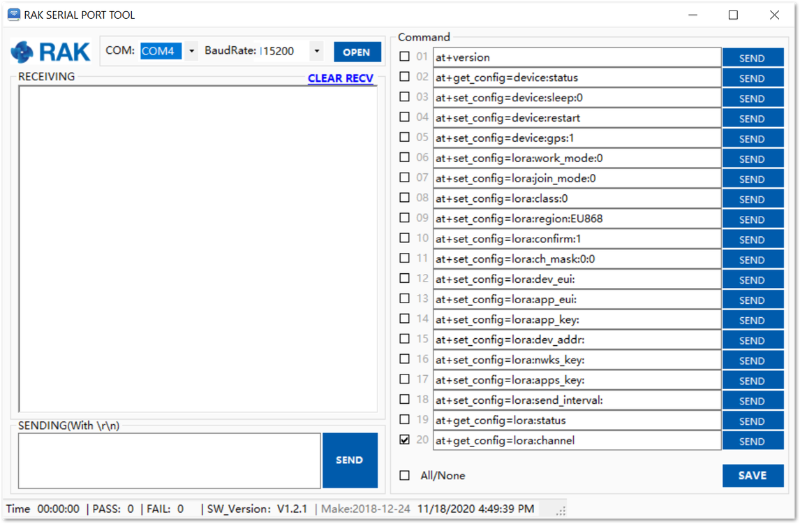 Figure 1: RAK Serial Port Tool
- For choosing the correct COM Port number for your device, go to your Device Manager by pressing the Windows key + R and type devmgmt.msc or search for the Device Manager in the Start menu. Once opened, look for Ports (COM & LPT) and find the name USB-SERIAL CH340. Take note of the COM Port Number, in this example it is COM4.
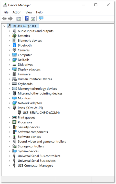 Figure 1: Device Manager
- Choose the correct COM port number from the device manager and the correct baud rate, then click Open. The default baud rate of the WisNode Button 4K is 115200 bps.
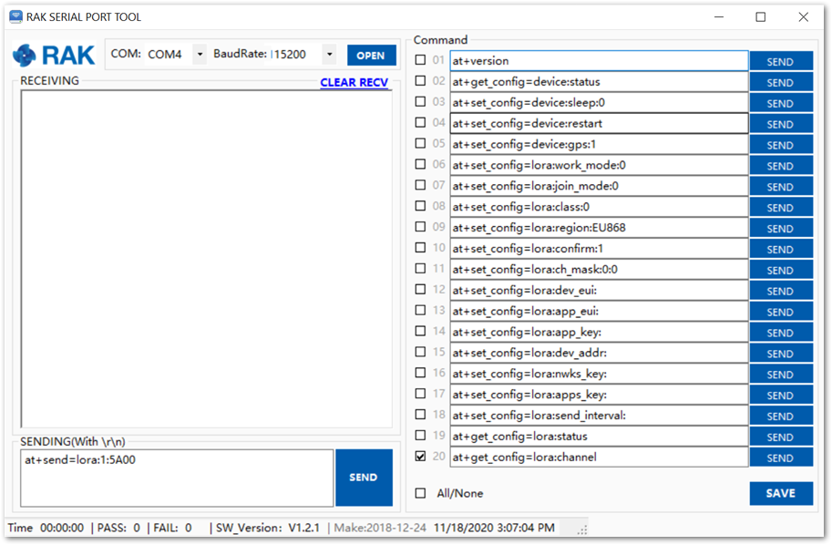 Figure 1: Correct COM port and baud rate are chosen
- To configure the Button, Configuration Mode must be entered. To do that, press Key 1 for three seconds. All blue LEDs will light up and you will have confirmation in the RAK Serial Port Tool.
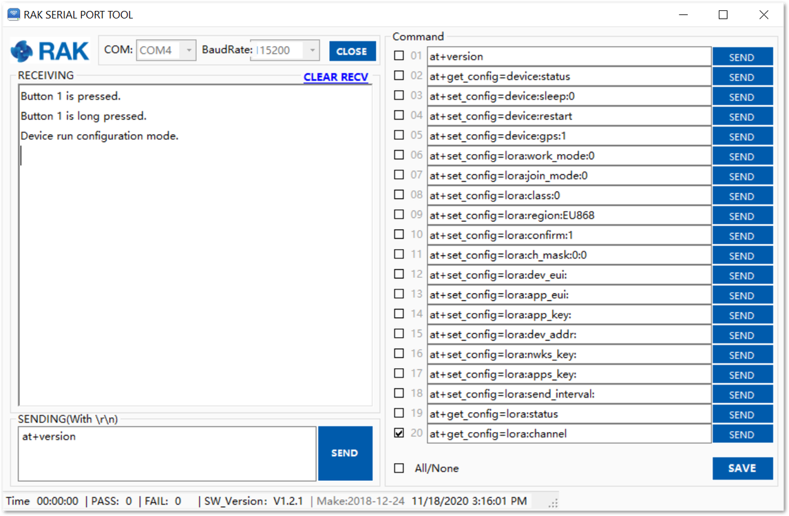 Figure 1: Confirmation for entering Configuration mode
- To check if the latest firmware version is in use, send the at+version command.
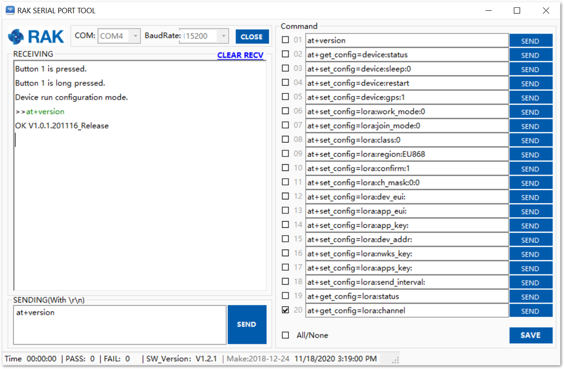 Figure 1: Checking the firmware version
Connecting to Helium (The People's Network)
Helium has quickly become the most widespread LPWAN communal network with more than 27,000 devices deployed globally. All our node products are compatible with it and the process of adding a device to the network is intuitive and straightforward.
This section will focus on giving a brief guide on how to connect the RAK7201 to the network console, assuming that there is a Helium Hotspot within range.
Log in or create your Helium account:
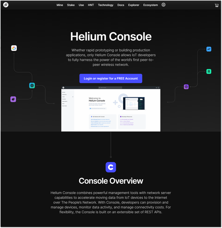 Figure 1: Helium console
Once registered/logged in you will end up at the home page where you can see your function tree on the left and your DC balance at the tops as well as a number of useful links.
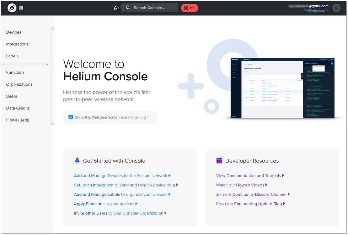 Figure 1: Helium console home screen
Go to the Devices section in the function tree. If this is your first time doing this there will be no devices registered. Click the + Add Device button to get started
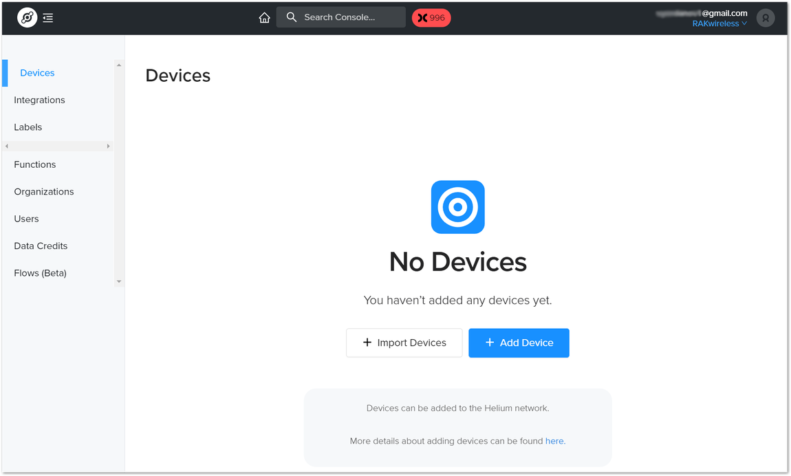 Figure 1: Helium devices
A window will pop up with a set of field containing the device parameters required for its registration.
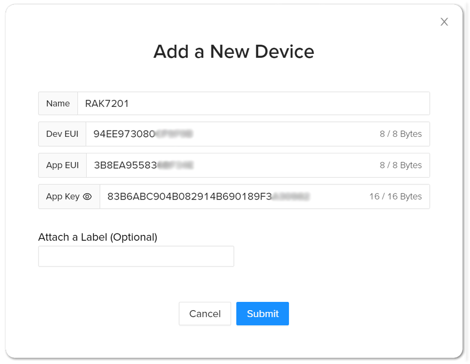 Figure 1: Add a new device
Fill in a name of your choosing. The Dev EUI, App EUI, and App Key will have random values generated for you by default. Press the eye icon to reveal the values. You can manually replace them with values of your own. For this tutorial, use the default values. Press the Submit button, and you are done.
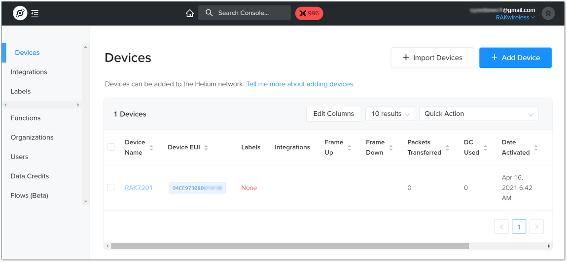 Figure 1: Helium devices
Now, your RAK7201 is registered and is awaiting activation. For this to happen we need to import the Dev EUI, App EUI and App Key in the RAK7201 using the RAK Serial Port Tool.
Open the tool, select the desired port (default baud rate) and open it. Hold Button 1 for 3 seconds to enter configuration mode and start importing your settings.
Configure your LoRa band and activation mode. This tutorial will be using the EU868 band and OTAA (only option available for now with Helium) with device class A (default one, does not need configuring).
- Regional band, device class and activation mode setting
at+set_config=lora:join_mode:0
at+set_config=lora:region:EU868
- Enter the Dev UI
Use the command below by replacing the XXXX with your Device EUI from the Helium console:
at+set_config=lora:dev_eui:XXXX
- Enter the App EUI
Same as with the Device EUI, replace the XXXX with your value:
at+set_config=lora:app_eui:XXXX
- Enter App Key
Finally fill in the App key with the command:
at+set_config=lora:app_key:XXXX
- Join Network
Finish executing the join command in order for the node to initiate the join procedure. Once the procedure is initiated and successfully complete you will have a notification in the serial console
at+join
You output should resemble the one in Figure 12.
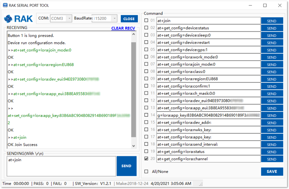 Figure 1: RAK7201 EUIs and key
If you take a look at the Helium console, you will also see the join request packets both in the graph and event log. Your node is now a part of the Helium Network.
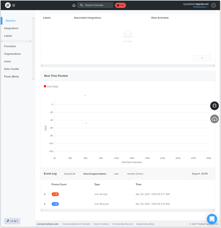 Figure 1: Helium console live device data
Connecting to Built-In Server
In this section, we will be connecting the RAK WisNode Button 4K to the Built-In server that is part of all RAK WisGate Series gateways.
Creating an Application
- Login into the gateway via the web UI and select the Application tab in the LoRa Network menu.
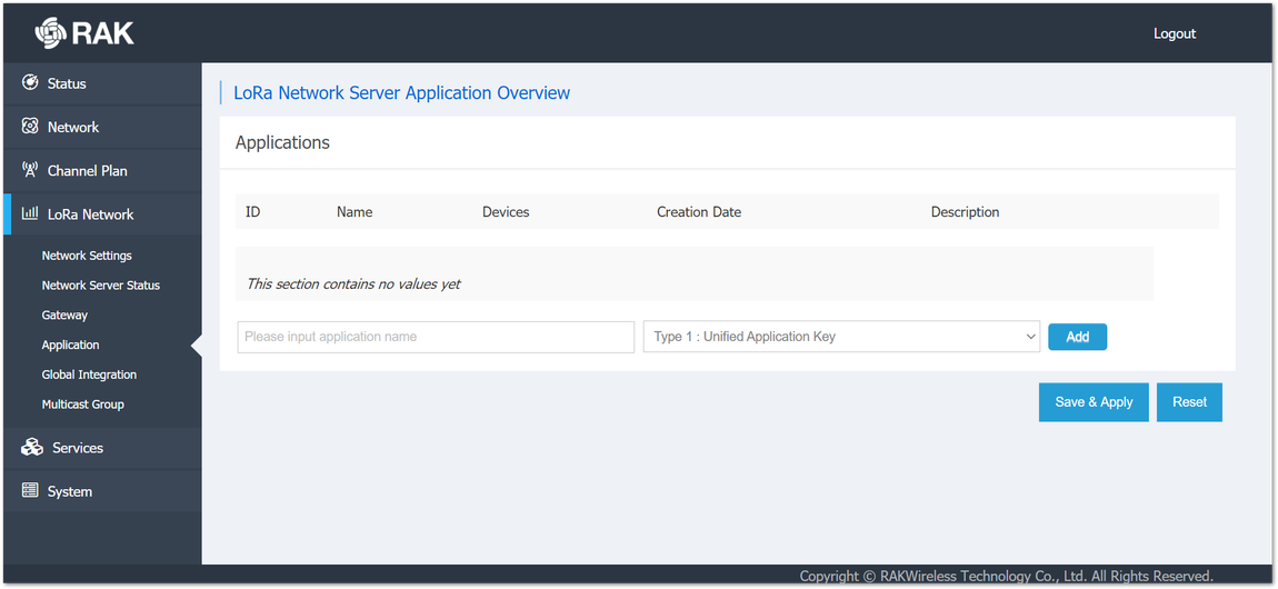 Figure 1: Application menu in the web UI of the gateway
- Input a name for the application and click the Add button.
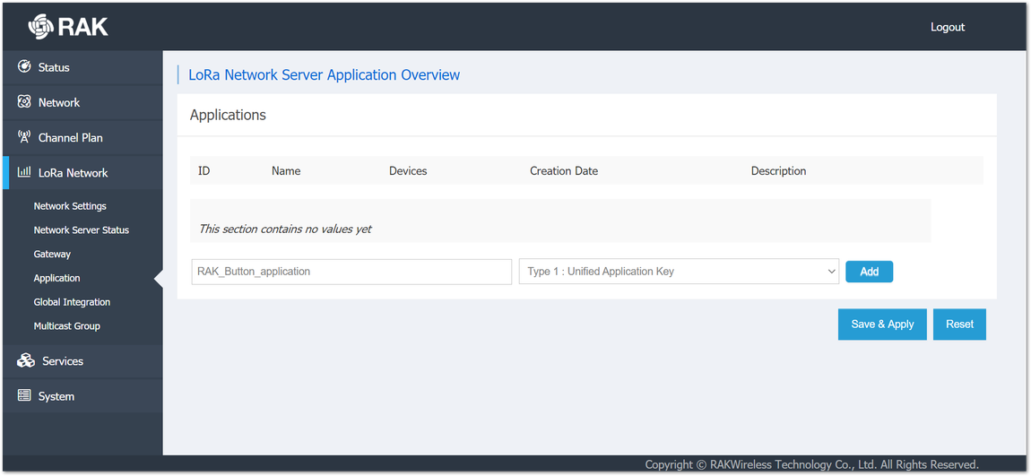 Figure 1: Creating an application
- Turn on the Auto Add LoRa Device switch and click the key generation icon next to the Application EUI and Application Key fields. This will generate the EUI and the Key automatically. Click Save and Apply.
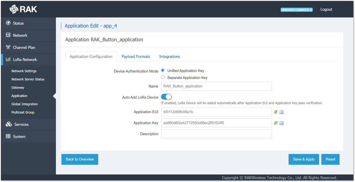 Figure 1: Application settings
Adding the Device to the Application
- In the created application, click on the Edit button as shown in Figure 17.
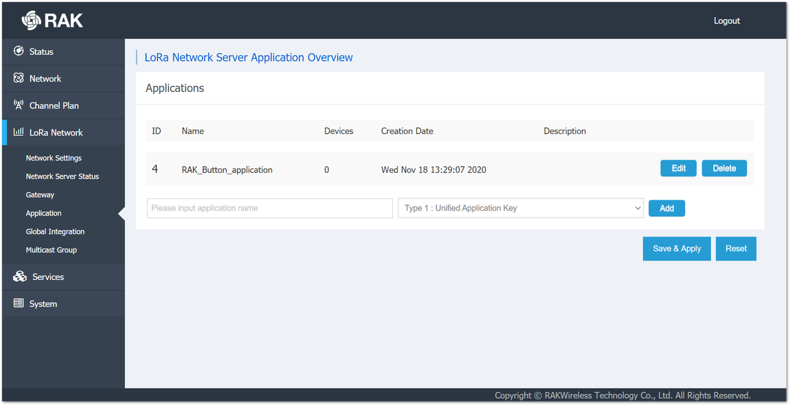 Figure 1: Application edit
- Enter the Device EUI in the corresponding input filed and press Add. You can find the Device EUI on the sticker on the back of the RAK WisNode Button 4K.
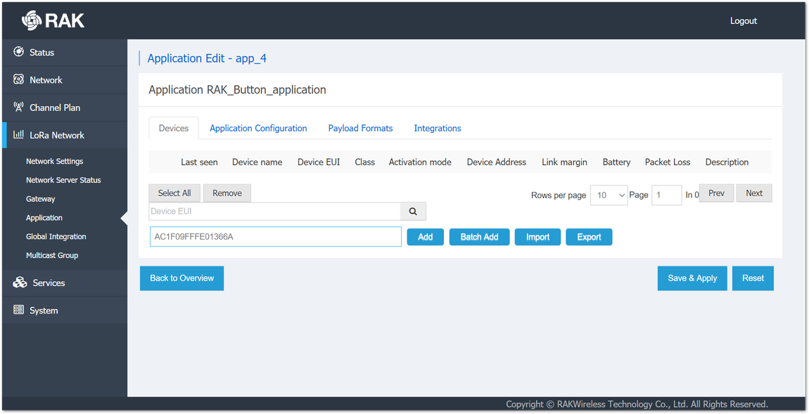 Figure 1: Adding the device
- Input a Device name of your choice. The Class is A and the Join Mode is OTAA by default. Leave the other fields as-is. Click Save And Apply.
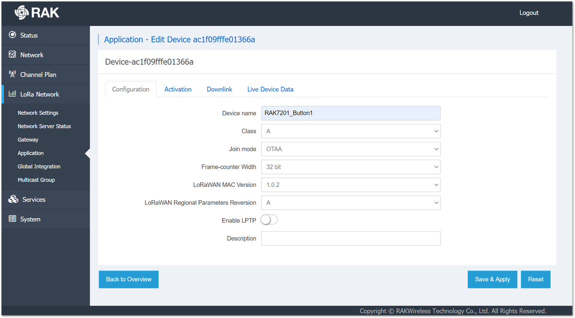 Figure 1: Configuring the devices settings
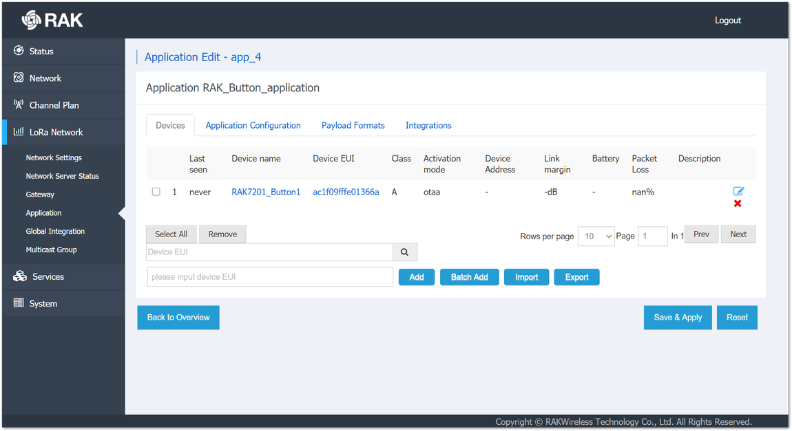 Figure 1: The device is registered
Configuring In OTAA Mode
- To manage to connect the Button to the Built-In Server in the gateway, a configuration with the correct parameters is needed. Using the AT commands and the RAK Serial Port Tool, the following parameters must be set:
- Join Mode (OTAA)
at+set_config=lora:join_mode:0
- Region (EU868 for this example)
at+set_config=lora:region:EU868
- Device EUI (on the sticker at the back of the device)
at+set_config=lora:dev_eui:ac1f09fffe01366a
- Application EUI (from the application configuration created previously in the gateway)
at+set_config=lora:app_eui:bf3112d69fc06a1b
- Application Key (from the application configuration created previously in the gateway)
at+set_config=lora:app_key:ea980d6f2e42772550c66ec2651f24f5
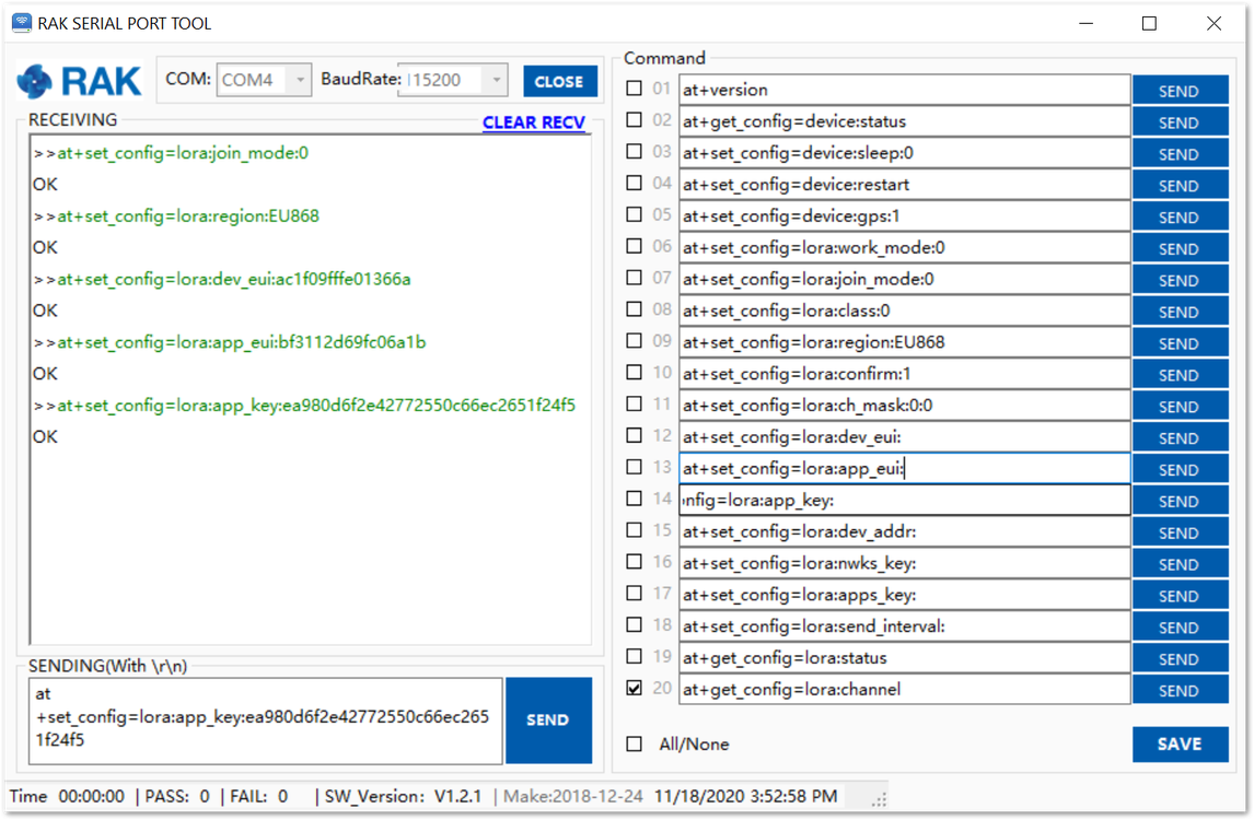 Figure 1: Configuring the RAK WisNode Button 4k in OTAA mode
- To connect to the LoRaWAN Network after the configuration, the device must be restarted. The restart command is:
at+set_config=device:restart
- After the restart, the device will try to join the LoRaWAN network automatically. If all the settings are configured correctly an OK Join Success message will be displayed in the RAK Serial Port Tool.
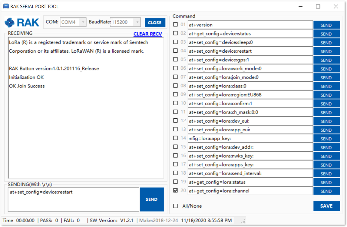 Figure 1: The device has restarted and connected to the LoRaWAN Network
- After the successful connection, the data obtained from pressing the buttons will be transmitted to the application server of the gateway.
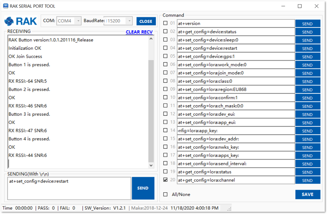 Figure 1: Successful operation of the buttons
- The received data from the WisNode Button 4K can be seen in the web UI of the gateway under Application > Device > Live Device Data.
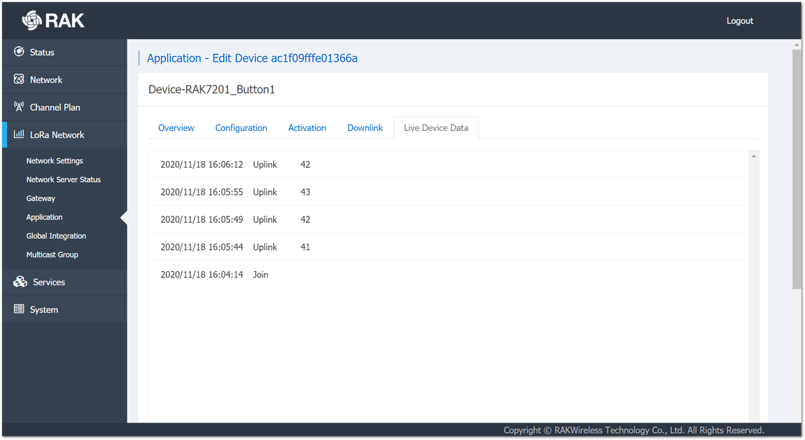 Figure 1: Received data
Configuring in ABP Mode
To use the RAK WisNode Button 4K in ABP mode, a change of the activation method is needed.
- Go to the Device configuration in the Gateway, as shown in Figure 25 and select the ABP Join mode from the drop-down menu.
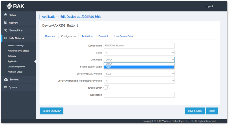 Figure 1: Changing the activation method
- Device Address, Application Session Key, and Network Session Key fields will appear. Enter the Device Address manually, it should be in HEX format and 8 digits long. To generate the needed keys automatically, click the key generation icon next to the Application Session key and Network Session Key fields. Click Save & Apply.
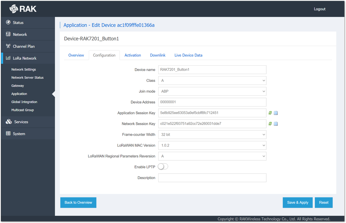 Figure 1: ABP mode configuration
- To set the WisNode Button 4K in ABP work mode, the following AT commands must be executed in the RAK Serial Port Tool:
- Join mode (ABP)
at+set_config=lora:join_mode:1
- Device Address (from the device configuration created previously in the gateway)
at+set_config=lora:dev_addr:00000001
- Application session key (from the device configuration created previously in the gateway)
at+set_config=lora:apps_key:5e8b925ee63053a9ef5cbff8fc712451
Network session key (from the device configuration created previously in the gateway)
at+set_config=lora:nwks_key:c021e522f93751a92cc72e260031dde7
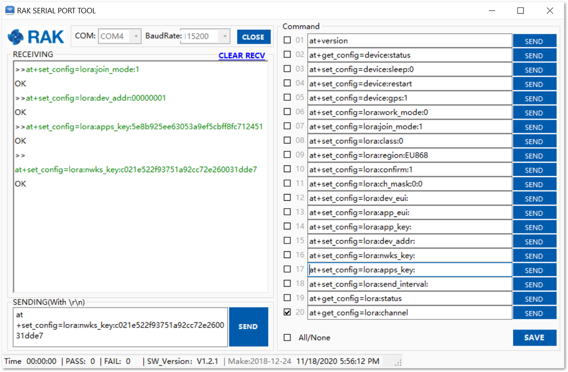 Figure 1: Configuring the WisNode Button 4K in ABP mode
- To connect to the LoRaWAN Network after the configuration, the device must be restarted. The restart command is:
at+set_config=device:restart
- After the restart, the device will be ready to send the information through the LoRaWAN Network.
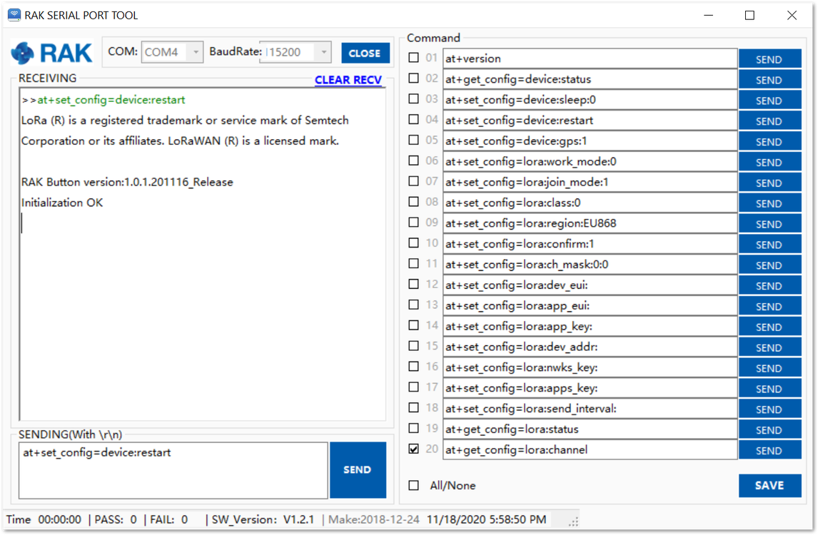 Figure 1: The device is restarted
In ABP mode there is no Join procedure. To be sure that the Button can send data you need to press the buttons and see if you have uplinks in the Live Device Data field of the device in the gateway.
- To test the ABP mode, press the buttons of the device.
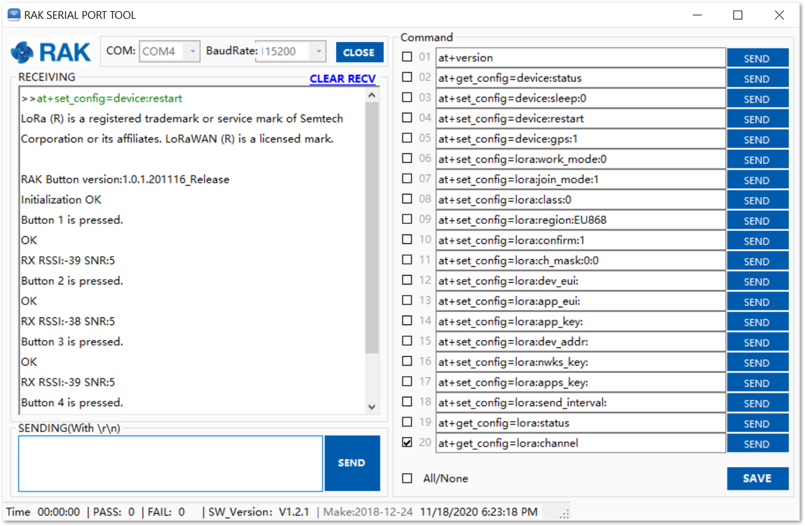 Figure 1: Testing the ABP mode
The received data from the WisNode Button 4K can be seen in the web UI of the gateway under Application > Device > Live Device Data.
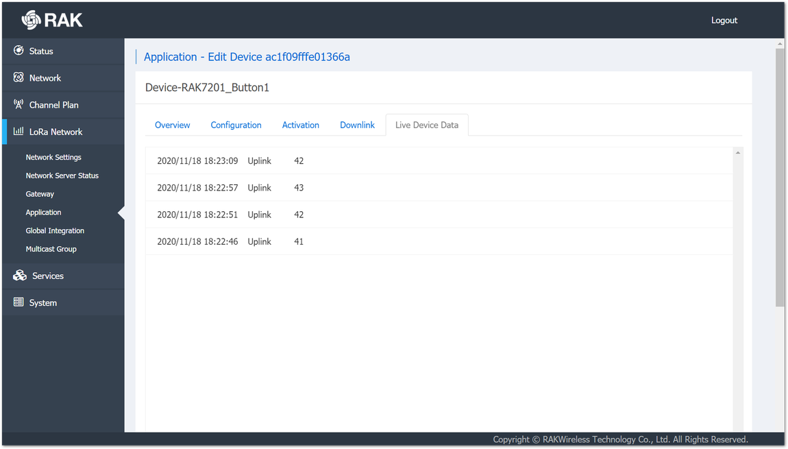 Figure 1: Received data
Connecting to The Things Network V3 (TTNv3)
At The Things Conference 2021, it was announced that The Things Network is upgrading to The Things Stack v3. In this section, it will be shown how to connect RAK7201 WisNode Button 4K to The Things Stack. To login into the TTNv3, head on to the TTN site. If you already have a TTN account, you can use your The Things ID credentials to log in.
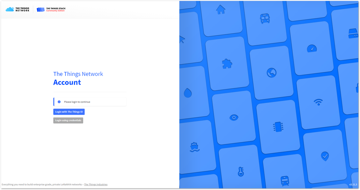 Figure 1: The Things Stack Home Page
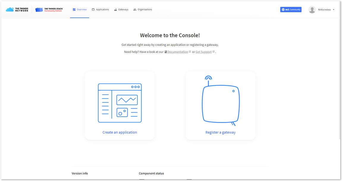 Figure 1: Console Page after successful login
To be able to connect RAK7201 WisNode Button 4K to TTNv3 you should already have connected a gateway in range to TTNv2 or TTNv3, or you have to be sure that you are in the range of a public gateway.
Adding an application
This tutorial is for EU868 Frequency band.
- To create an application, choose Create an application (for new users that do not already have created applications) or Go to applications > + Add application (for users that have created applications before).
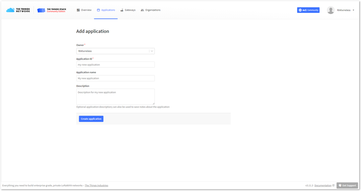 Figure 1: Create an application page
- Fill in the needed information:
- Owner – Automatically filled by The Things Stack, based on your account or created Organization.
- Application ID - This will be the unique ID of your application in the Network. Note that the ID must contain only lowercase letters, numbers, and dashes (-).
- Application name (optional) - This is the name of your application.
- Description (optional) – Description of your application. Optional application description; can also be used to save notes about the application.
- After you fill in the information, click Create application. If everything is filled in correctly, you will see the page in Figure 34.
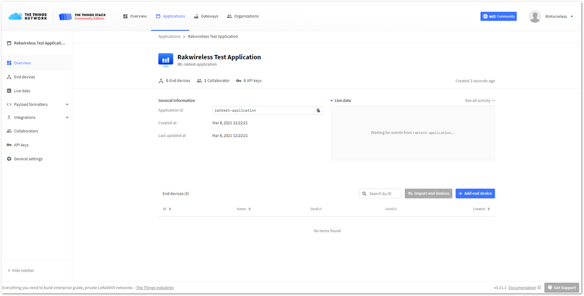 Figure 1: Application Overview
Registering and Configuring the Device In OTAA Mode
Registering the Device in OTAA Mode
- From the Application Overview page, click on + Add end device.
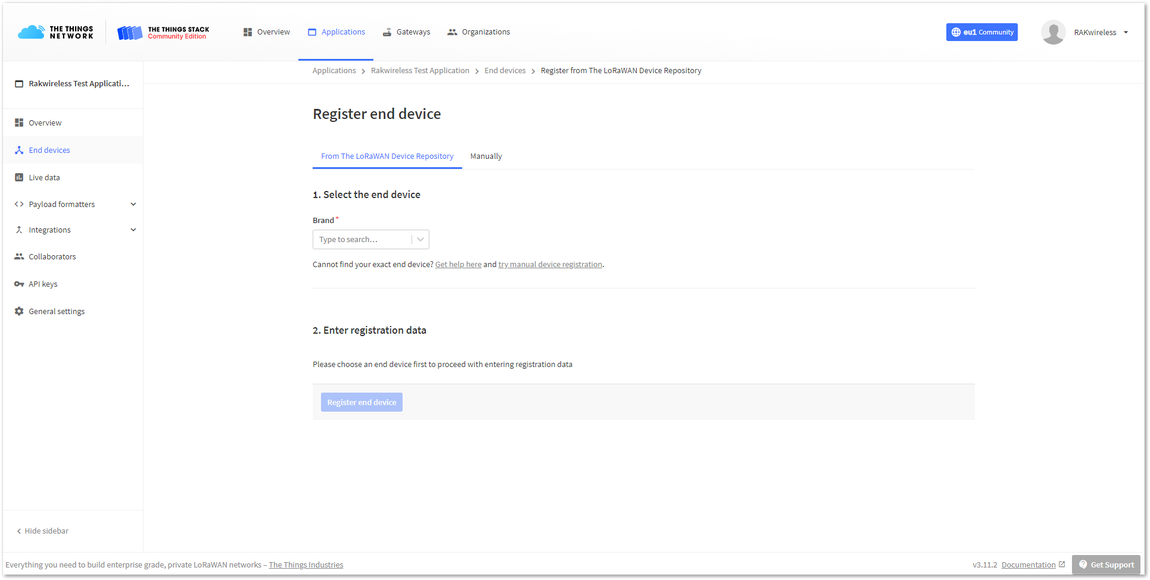 Figure 1: Adding a device in OTAA mode
- Bellow the Register end device heading you can find two options for registering a device. Choose Manually. For Activation mode choose Over the air activation (OTAA) and for the LoRaWAN version choose MAC V1.0.2 (RAK7201 is LoRaWAN 1.0.2 fully compliant).
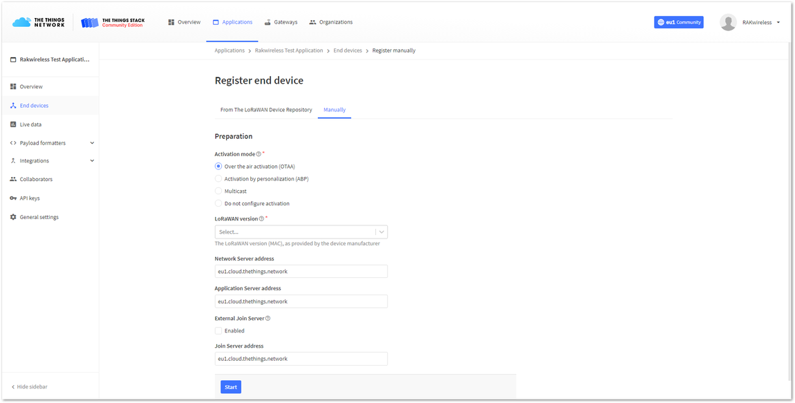 Figure 1: Registering the device in OTAA mode
- To get to the next step of the registration, click Start.
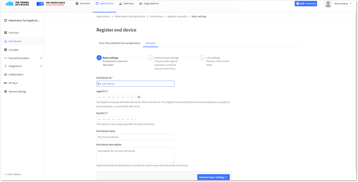 Figure 1: Basic settings for OTAA mode
- Fill in the Basic settings for the device:
- End device ID - This is the unique identifier for your RAK7201 WisNode Button 4K in your application. You need to enter this manually. Note that the End device ID must contain only lowercase letters, numbers, and dashes (-).
- AppEUI - The AppEUI uniquely identifies the owner of the end device. It is provided by the device manufacturer. To get the AppEUI, connect your device via USB cable to your computer. Open RAK Serial Port Tool, choose the correct COM port and BaudRate and hold Button 1 for 3 seconds to enter the device in Configuration mode.
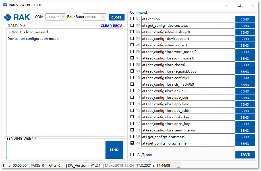 Figure 1: Configuration mode of RAK7201
Then run the following command:
at+get_config=lora:status
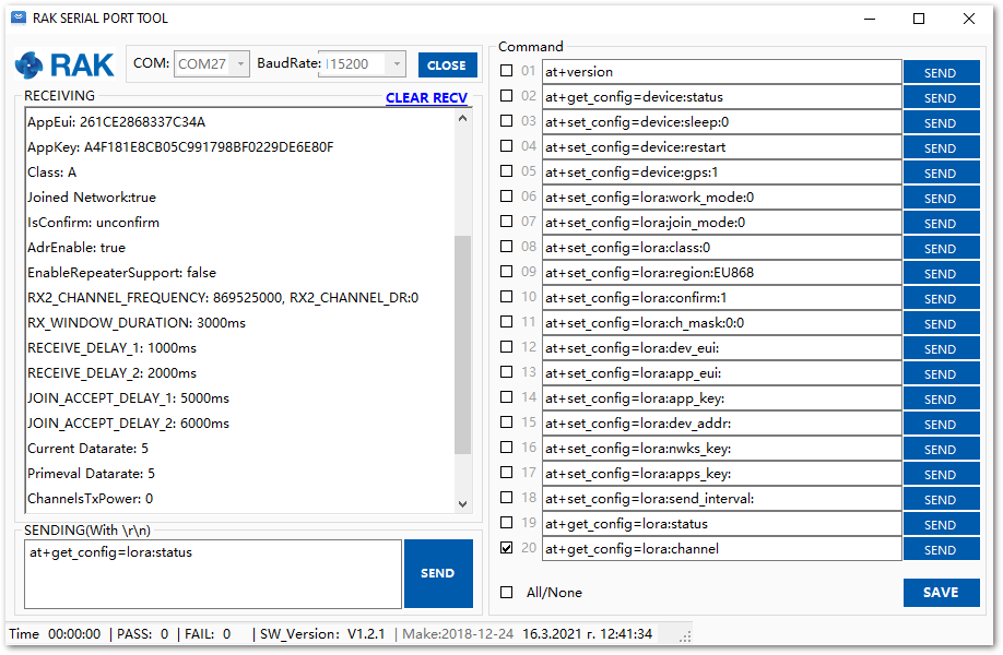 Figure 1: AppEUI of the device
- DevEUI - The DevEUI is the unique identifier for this end device. It can be found on a sticker on the back of the device.
- End device name (optional) - A unique, human-readable identifier for your device. You make it up, so be creative. Device IDs cannot be used by multiple devices within the same application.
- End device description (optional) - Optional end device description; can also be used to save notes about the end device.
- Click Network layer setting.
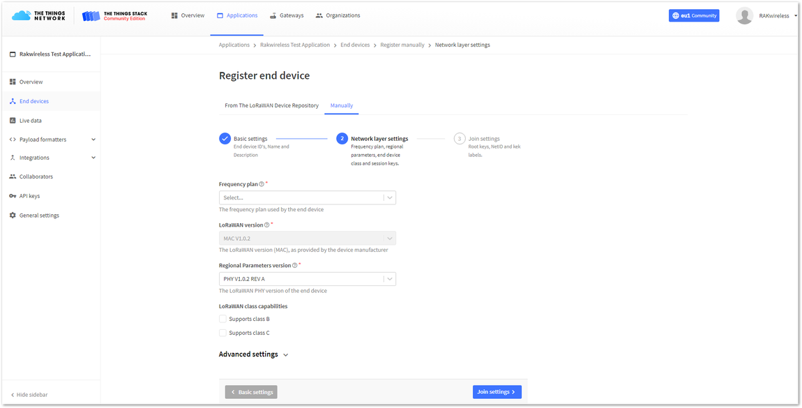 Figure 1: Network layer setting for OTAA mode
- Here you must configure the Network layer settings for the device:
- Frequency plan - The frequency plan used by the end device. Note that, for this tutorial, the frequency plan used is Europe 863-870 MHz (SF9 for RX2 – recommended).
- Regional Parameters version - The Regional Parameters specify frequency, dwell time, and other communication settings for different geographical areas. The Regional Parameters version is the version of the LoRa Alliance specification which your device supports. This should be provided by the device manufacturer in a datasheet. For this example, PHY V1.0.2 REV A is chosen.
- LoRaWAN class capabilities – Here you can select if your device supports class B, class C, or both.
- In Advanced settings, you can configure additional settings for your device.
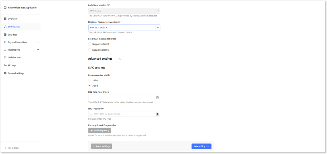 Figure 1: Advanced network layer settings of the device
For this example, these settings will be left as default.
- Click Join settings.
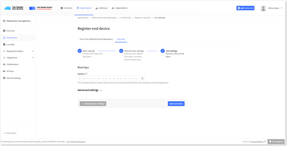 Figure 1: Join settings for OTAA mode
- Here you must fill in your Application key (AppKey) to secure communication between the end device and the application. The AppKey can be generated automatically by clicking the Generate button next to the AppKey field.
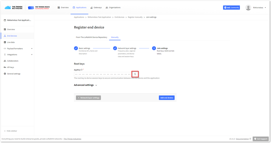 Figure 1: Generate App Key Button
- In the Advanced settings, you can configure more options about your device.
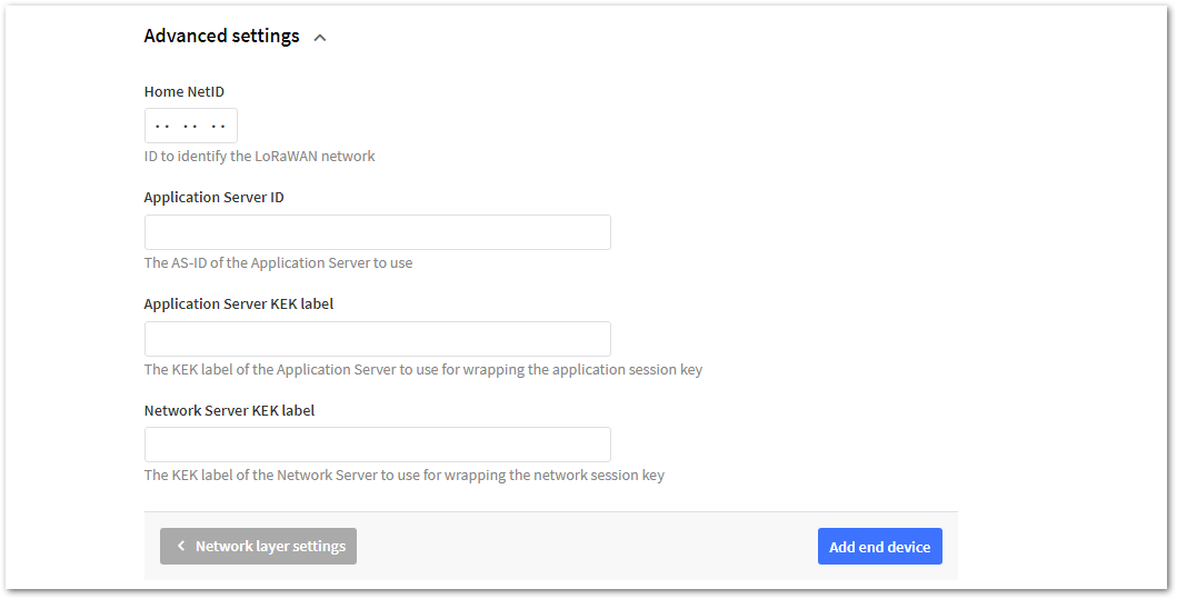 Figure 1: Advanced join settings for OTAA mode
For this example, these settings will be left as default.
- Finally, to finish registering your device, click Add end device.
Configuring the Device in OTAA Mode
- For configuring the node you will need the following three parameters: Device EUI, Application EUI, and Application Key. You can see them all in the Device Overview page, but since the two EUI's come with the device, you only need the Application Key from there.
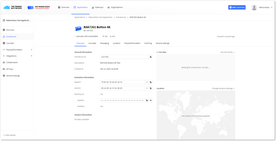 Figure 1: OTAA device parameters
- To configure the Button, it must be in Configuration Mode. To do that, press Key 1 for three seconds until all blue LED lights up and you receive confirmation in the RAK Serial Port Tool. Using the RAK Serial Port Tool, set the join mode, device class, and your LoRaWAN region to your correct frequency band, with the following set of AT commands:
- For the join mode (OTAA)
at+set_config=lora:join_mode:0
- For the class (Class A)
at+set_config=lora:class:0
- For the Frequency (Remember to replace the frequency band with the one for your LoRaWAN region. Check here for your frequency plan.)
at+set_config=lora:region:EU868
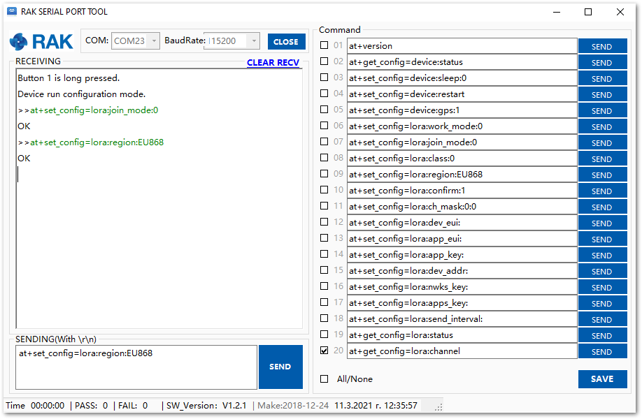 Figure 1: Setting up the RAK7201 WisNode Button 4K operation mode
The following tutorial is based on using the EU868 frequency band.
- Now that those parameters are set, enter the App Key, using the command below. Remember to replace the "XXXX" with the corresponding parameter value for your particular case.
at+set_config=lora:app_key:XXXX
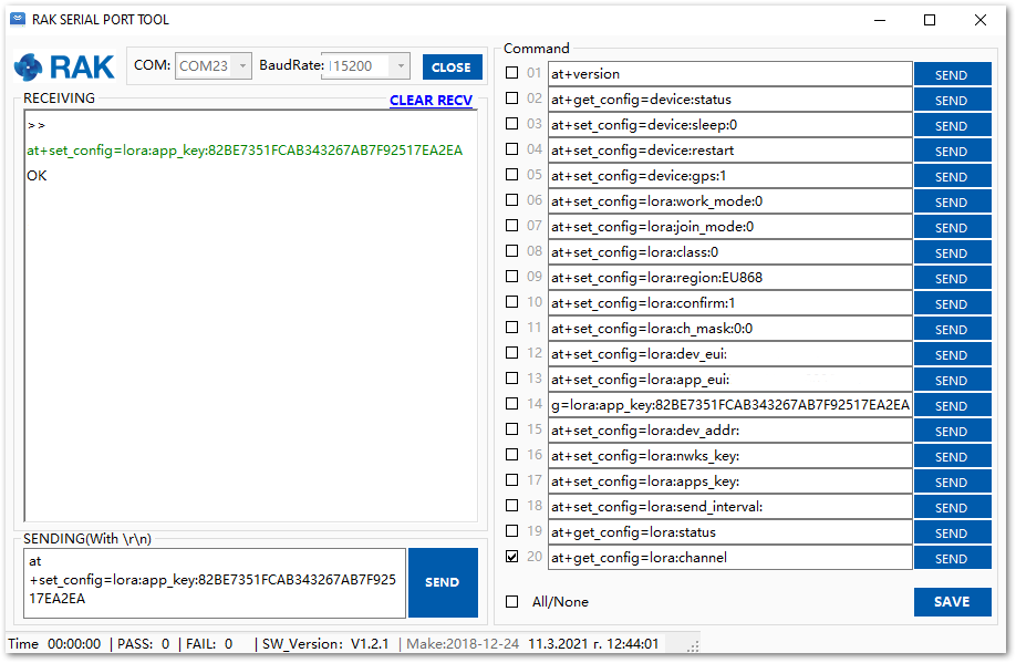 Figure 1: Setting up the RAK7201 WisNode Button 4K OTAA parameters
- To connect to the LoRaWAN Network after configuration, the device must be restarted. Run the following command to restart it:
at+set_config=device:restart
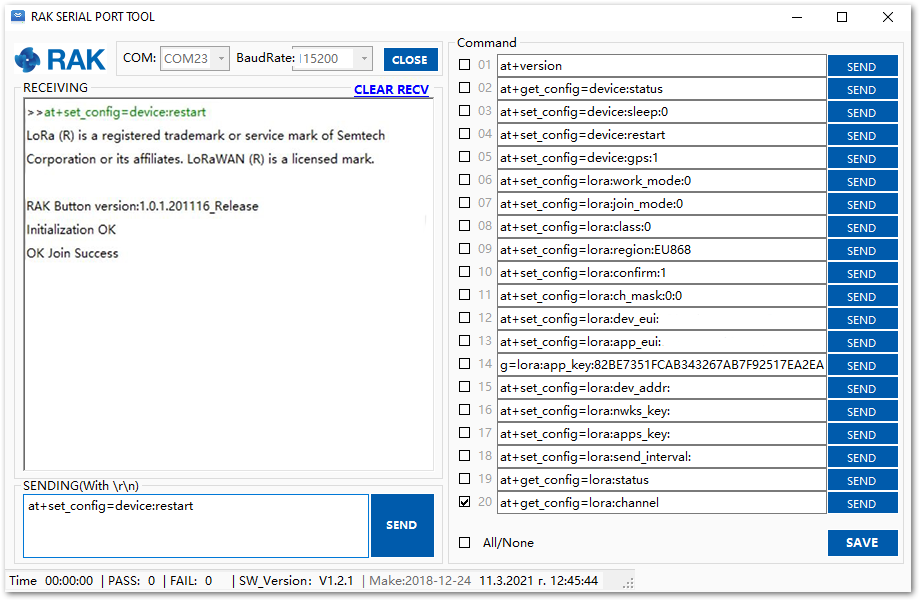 Figure 1: Join confirmation
- After the successful connection, the data obtained from pressing the buttons will be transmitted to the application server of the gateway.
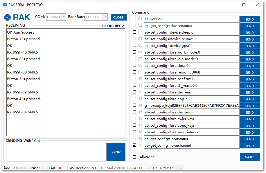 Figure 1: Transmitted data seen in the RAK Serial Port Tool
- The received data from the WisNode Button 4K can be seen in the Live data feed.
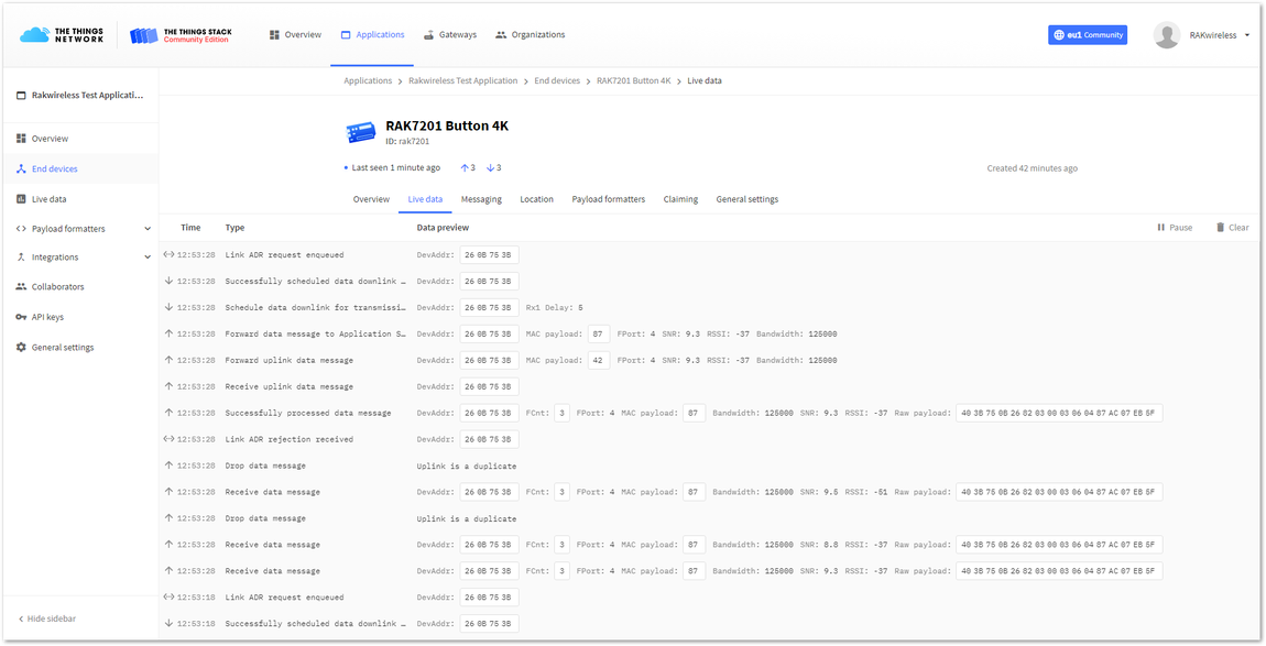 Figure 1: Sending data to The Things Stack from RAK7200 WisNode Track Lite
Key Functions
In this section, the main functionality of the different keys (buttons) of the device will be addressed.
Default payload data of the keys:
| Key | Data |
|---|---|
| Key 1 | A |
| Key 2 | B |
| Key 3 | C |
| Key 4 | D |
To customize the data sent by every button, the following AT command is used:
at+button=<button>:<port>:<data>
Where:
<button>- The configured key (range 1-4)<port>- Configured port number (range 1-223)<data>- The sent data (max length is 10 characters)
Example:
Change the data sent from the pressing of button 1 to HelloWorld using the command:
at+button=1:1:HelloWorld
To check the data of the buttons you can execute the command:
at+get_config=device:status
The result is shown in Figure 51.
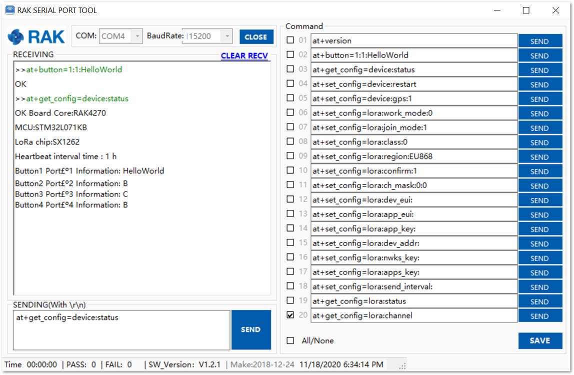 Figure 1: Changing the data sent from button 1
Key functions:
| Function | Description |
|---|---|
| Key 1 | Long press Key 1 for three seconds. the device enters or exits configuration mode. Short press Key 1 to send Key 1 data. The data can be personalized with an AT command. |
| Key 2 | Long press Key 2 for three seconds, the device resets. Short press Key 2 to send Key 2 data. The data can be personalized with an AT command. |
| Key 3 | Short press Key 3 to send Key 3 data. The data can be personalized with an AT command. |
| Key 4 | Short press Key 4 to send Key 4 data. The data can be personalized with an AT command. |
When the device is still sending after the button is pressed, if the user presses a key again, the device will ignore this action. Only when the device is not sending, the user's key action will be accepted.
LEDs Functions
| LED function | Description |
|---|---|
| Blue LED corresponding to each button flash one | Corresponding LED will flash once when the button is pressed. |
| Blue LED corresponding to each button flash twice | Corresponding LED will flash twice when the data transmission is successful. |
| Key 4 red LED flash twice | Data transmission is not successful. |
| Key 4 red LED flash for 1 sec | One flash Indicates that the WisNode Button 4K is not connected to the Network, after the user press any button. Two flashes Indicate that the join procedure have failed. |
| All four blue LEDs flash at once for 1 second | Joining the network is successful. |
| All blue LEDs flash clockwise 1-2-4-3 | The device is trying to join the network. |
| Key 2 red LED | Indicates battery charging mode. You can charge the battery of the WisNode Button 4k via the micro USB port. When the red LED on Button 2 is on – the battery is charging, when it goes off – the battery is charged. |
| All four blue LEDs are on | The device is in configuration mode. |
HeartBeat function
The HeartBeat is used to monitor the network connection and to send the battery level information of the WisNode Button 4K.
The device can send a HeartBeat packet according to the configured HeartBeat interval. The AT command for configuring the HeartBeat interval is:
at+heartbeat=<interval>
Where the interval range is 0-120 (in hours), 0 to turn off the function.
Example:
Set the HeartBeat to one hour using the command:
at+heartbeat=1
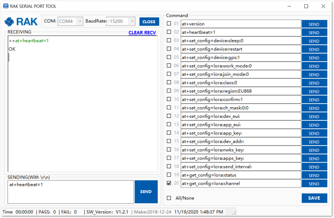 Figure 1: Set the HeartBeat interval
The HeartBeat message data format is:
| Headers | Payload |
|---|---|
| 0X48 | Battery level in HEX |
The battery level is represented in percentage form in hexadecimal format.
For example: If the payload message of the HeartBeat is 48 60, this represents 96% battery level.
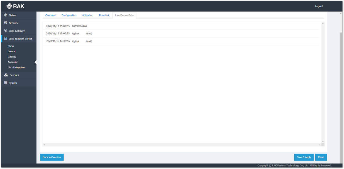 Figure 1: HeartBeat message in the Live Device Data
The device will automatically send a low-voltage alarm signal when the battery power is below 20% and again when it is below 10%. Battery power warning signal:
| Battery power | Warning signal |
|---|---|
| Power is less than 20% | 57 14 |
| Power is less than 10% | 57 0a |
Device Restart
Two restart options are available:
- You can restart the device by using the AT command:
at+set_config=device:restart
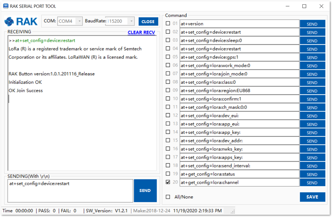 Figure 1: Restarting with an AT command
- You can restart the device by holding Key 2 for three seconds. When held, the blue LED will stay lit, and will turn off when the device is restarted.
After the device restart manually or by AT command the WisNode Button 4K will try to join the network automatically if the OTAA method is configured. This will be indicated by 4 blue LEDs flashing clockwise. The device will make three attempts to Join the Network. If a Join attempt fails, the red LED on button 4 will flash for 1 second. If the three join attempts are failed, the device needs to be restarted manually or by AT command to make a new attempt.
