Guidelines for CE and FCC Certifications
This guide outlines the AT commands used during CE and FCC certification tests for WisDuo-based devices running RUI3 firmware.
It is not a complete testing guide but a reference to help you execute the required AT commands during certification procedures.
You can download the CE and FCC certification guides as PDF files, along with the COMTool serial terminal application, from the RUI3 section of our Download Center.
The latest RUI3 firmware versions are available in the Image folder within the same section.
Contents
CE Certification Guide
Test Overview
This document uses the RAK3172 LoRa module as an example for the CE RF certification test. It covers test requirements, RF performance, configurations, and step-by-step testing procedures for the 863-870 MHz band.
Test Standards & Scope
| Parameters | Specification |
|---|---|
| Applicable Standard | EN 300 220-2 |
| Test Band | 863–870 MHz |
| Test Modes | LoRa modulation, FSK modulation |
Technical Parameters
LoRa Technical Parameters
| Parameters | Specification |
|---|---|
| Operating Frequency |
|
| Modulation | LoRa / FSK |
| Data Rate | LoRa (SF7–SF12); FSK (50 kbps) |
| Occupied Bandwidth | LoRa 125 kHz / 250 kHz FSK 50 kbps (~100 kHz) |
Power Limit Requirements
| Parameters | Specification |
|---|---|
| Max Transmit Power | Band P at 869.525 MHz≤ 27 dBm Other channels: < 14 dBm |
| Test Signal | Continuous transmission (LoRa/FSK), DM-2 signal |
Test Bands & Channel List
LoRa 125 kHz / FSK Channel List
(EN 300220-2 Annex B Table B.1)
| Band | Center Frequency (MHz) | Operating Band (MHz) |
|---|---|---|
| K | 863.1 | 863-865 |
| K | 864.9 | 863-865 |
| L | 865.1 | 865-868 |
| L | 867.9 | 865-868 |
| M | 868.1 | 868-868.6 |
| M | 868.5 | 868-868.6 |
| N | 868.8 | 868.7-869.2 |
| N | 869.1 | 868.7-869.2 |
| P | 869.5 | 869.4-869.65 |
| P | 869.55 | 869.4-869.65 |
| R | 869.8 | 869.7-870 |
| R | 869.9 | 869.7-870 |
LoRa 250 kHz Channel List
(EN 300220-2 Annex B Table B.1)
| Band | Center Frequency (MHz) | Operating Band (MHz) |
|---|---|---|
| K | 863.2 | 863-865 |
| K | 864.8 | 863-865 |
| L | 865.2 | 865-868 |
| L | 867.8 | 865-868 |
| M | 868.2 | 868-868.6 |
| M | 868.4 | 868-868.6 |
| N | 868.9 | 868.7-869.2 |
| N | 869.0 | 868.7-869.2 |
| P | 869.525 | 869.4-869.65 |
| R | 869.85 | 869.7-870 |
Test Preparation
Equipment List
| Item | Qty |
|---|---|
| Laptop | 1 |
| DUT (Device Under Test) | 1 |
| USB-to-UART Converter | 1 |
| Dupont Wires | 4 |
Hardware Connection
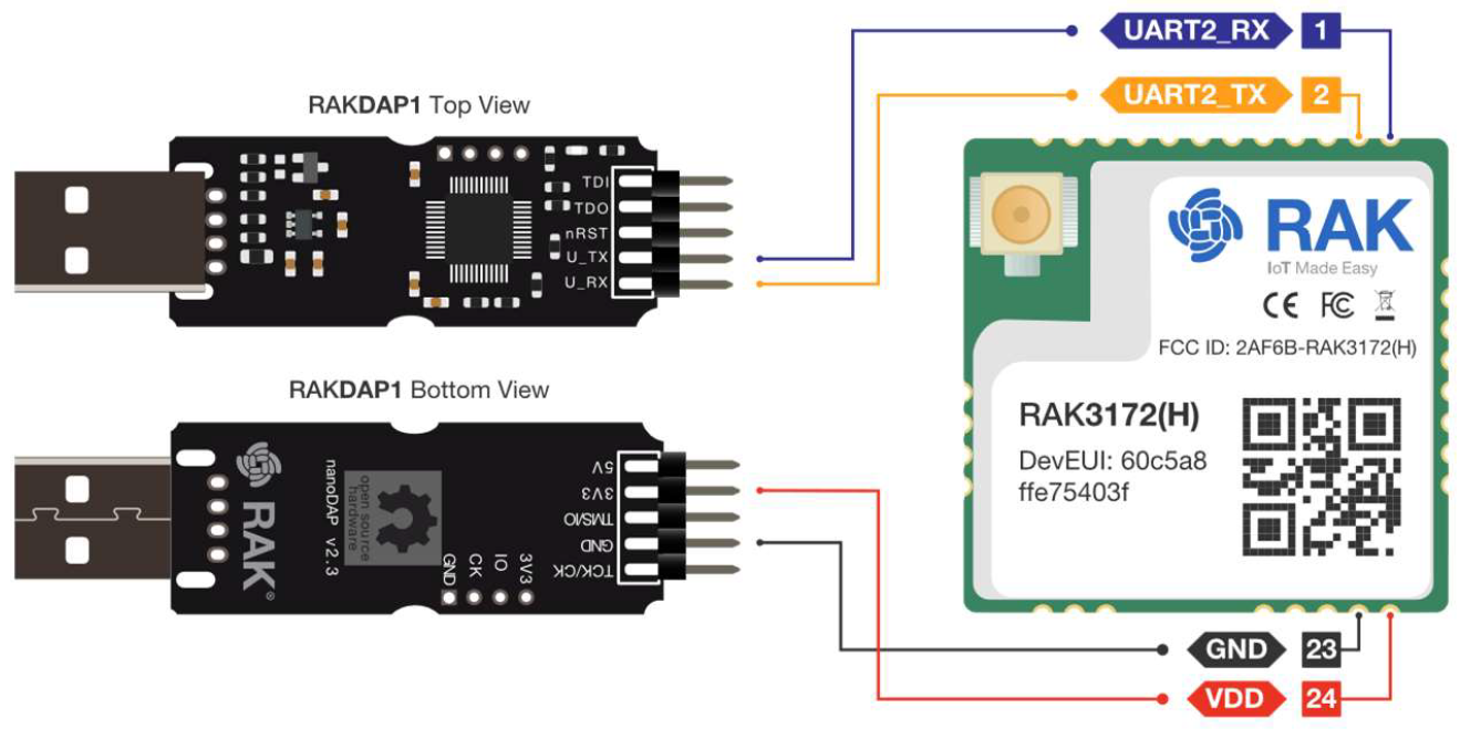 Figure 1: Hardware connection diagram
When the module is integrated into a host device (e.g. a WisBlock Core module), connect the device's USB interface to the PC using a data cable.
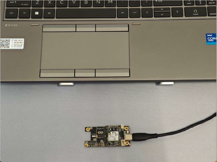 Figure 1: Hardware connection for devices with USB connection
Software Configuration
Serial Tool Setup
In this guide the, COMTool v3.4.1 for Windows is used. Other serial terminal applications can be used if they support 115200 baud and append CR LF (\r\n) after sending commands.
- Select the actual COM port of the device.
- Check DTR and click OPEN to open the port.
- Set the remaining options as shown in Figure 3.
- Type test commands in the Command Input Box.
- Click the Send button to transmit the command to the DUT.
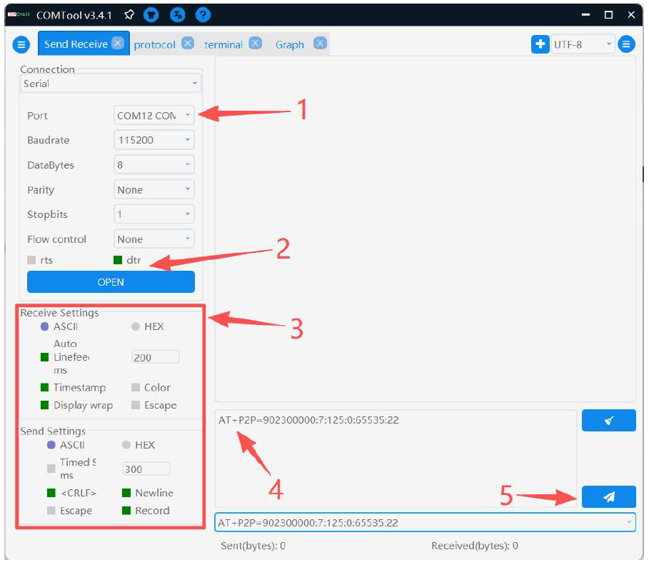 Figure 1: Serial terminal setup
RF Test Commands
LoRa Commands
Send the AT commands in the following order:
| Function | AT Command | Parameters |
|---|---|---|
| 1. Set operating mode | AT+NWM=0 | |
| 2. Configure LoRa parameters | AT+P2P=<Frequency>:<SF>:<Bandwidth>:<CR>:<Preamble>:<Power> Example: AT+P2P=868000000:7:125:0:65535:14 |
|
| 3. Start transmission (sends a waveform) | AT+PSEND=<payload> Example: AT+PSEND=11223344 |
Example Commands
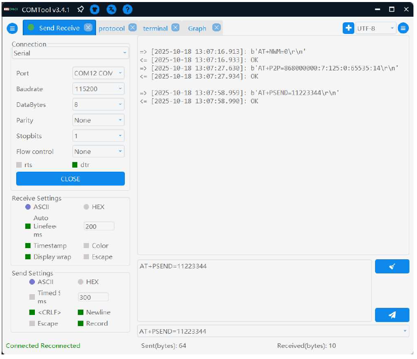 Figure 1: Example Commands
LoRa Test Waveform
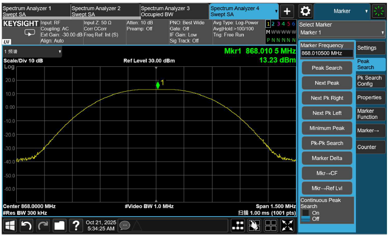 Figure 1: LoRa Test Waveform
CW Command (Frequency Accuracy Test)
| Function | AT Command | Parameters |
|---|---|---|
| Starts continuous-wave transmission for PPM frequency accuracy testing. A single command is sufficient to enter the test mode. | AT+CW=<Frequency>:<Power>:<Duration> Example: AT+CW=868000000:20:500 |
|
CW Test Waveform
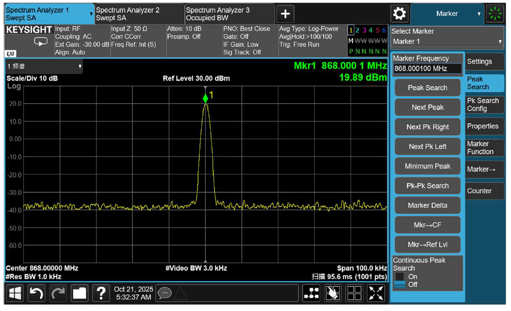 Figure 1: CW Test Waveform
FSK RF Test
For FSK configuration, send the AT commands in the following order:
During testing, only modify the test frequency and RF power as you iterate through channel points. Use the FSK send-data command to continue testing on subsequent channels.
| Function | AT Command |
|---|---|
| 1. Set FSK mode | AT+NWM=2 |
| 2. Set test frequency | AT+PFREQ=868000000 |
| 3. Set RF power | AT+PTP=22 |
| 4. FSK bit rate | AT+PBR=50000 |
| 5. FSK frequency deviation | AT+PFDEV=25000 |
| 6. Preamble length | AT+PPL=300 |
| 7. Start FSK data transmission (Use a long payload to maintain signal at the fastest FSK rate.) | AT+PSEND=<payload> |
Example payload:
AT+PSEND=1122334455667788998877665544332211223344556677889988776655443322112233445566778899887766554433221122334455669988778899887766554433221122334455667788998877665544332211
Before sending the last command, enable Timed Send in the tool and set the interval to 300 ms. Refer to labels 1-3 in Figure 7.
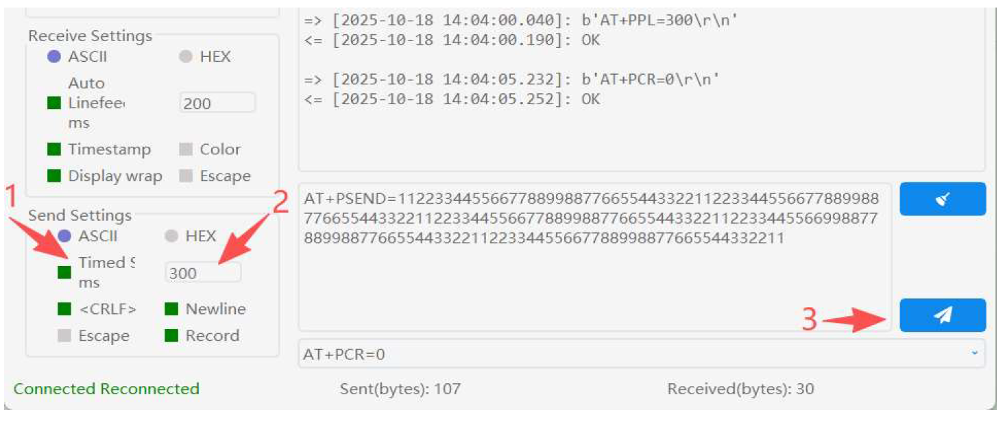 Figure 1: FSK Test Setup
FSK Test Waveform
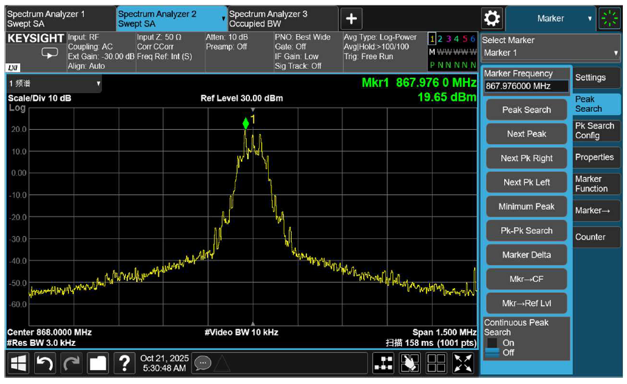 Figure 1: FSK Test Waveform
Stop Transmission Command
If timed send is enabled, remember to disable it. Use this command:
AT+TOFF
EMS Immunity — RX Blocking — ERP
Prepare two sets of devices: one configured as TX (transmitter) and the other as RX (receiver).
During testing, an interferer is injected to jam the receiver. The RX device should remain in its normal receiving state throughout the procedure.
Device Command Setup
| Function | RX Device | TX Device |
|---|---|---|
| 1. Set identical operating mode | AT+NWM=0 | AT+NWM=0 |
| 2. Set identical LoRa parameters | AT+P2P=868000000:7:125:0:8:14 | AT+P2P=868000000:7:125:0:8:14 |
| 3. RX continuous receive | AT+PRECV=65534 | |
| 4. TX packet send | AT+PSEND=11223344 |
On the TX device, enable timed send and set the interval to 2000 ms.
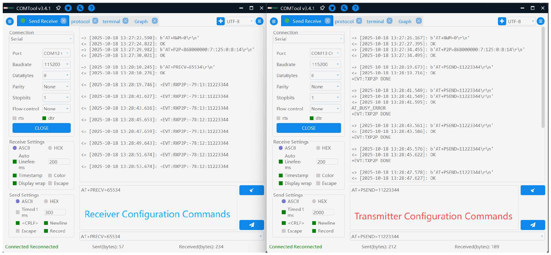 Figure 1: Test command setup
FCC Certification Guide
Test Overview
This document uses the RAK3172 LoRa module as an example and serves as an FCC RF certification test guide, covering RF performance test requirements, configurations, and procedures for the 902–928 MHz band.
Test Standards & Scope
Applicable Standard: 47 CFR §15.247
Test Band: 902-928 MHz
Test Mode: LoRa modulation
LoRa Technical Parameters
FHSS Mode
| Parameters | Specification |
|---|---|
| Operating Frequency | 902.3 MHz-914.9 MHz |
| Modulation | LoRa |
| Data Rate | SF7-SF10 / DR0-DR3 |
| Number of Channels | 64 channels across 902.3-914.9 MHz |
| Channel spacing | 200 kHz |
| Occupied Bandwidth | 125 kHz |
| Power Limit | < 0.125 W (< 21 dBm) |
DTS Mode
| Parameters | Specification |
|---|---|
| Operating Frequency | 903 MHz-914.2 MHz |
| Modulation | LoRa |
| Data Rate | SF8 / DR4 |
| Number of Channels | 8 |
| Channel spacing | 1.6 MHz |
| Occupied Bandwidth | 125 kHz |
Each test item must be executed at the specified data rates. Commands for switching rates are provided later in this guide.
LoRa Channel Plan
A. FHSS Channel List
| Channel No. | Frequency (MHz) |
|---|---|
| 1 | 902.3 |
| 2 | 902.5 |
| 3 | 902.7 |
| 4 | 902.9 |
| 5 | 903.1 |
| 6 | 903.3 |
| 7 | ...+200 kHz |
| 8 | 914.9 |
B. DTS Channel List
| Channel No. | Frequency (MHz) |
|---|---|
| 1 | 903 |
| 2 | 904.6 |
| 3 | 906.2 |
| 4 | 907.8 |
| 5 | 909.4 |
| 6 | 911.0 |
| 7 | 912.6 |
| 8 | 914.2 |
C. Data-Rate Information
| DR | Configuration | Indicative Physical Bit Rate (bit/s) |
|---|---|---|
| 0 | LoRa Modulation: SF10 / Bandwidth 125 kHz | 980 |
| 1 | LoRa Modulation: SF9 / Bandwidth 125 kHz | 1760 |
| 2 | LoRa Modulation: SF8 / Bandwidth 125 kHz | 3125 |
| 3 | LoRa Modulation: SF7 / Bandwidth 125 kHz | 5470 |
| 4 | LoRa Modulation: SF8 / Bandwidth 500 kHz | 12500 |
| 8 | LoRa Modulation: SF12 / Bandwidth 500 kHz | 980 |
| 9 | LoRa Modulation: SF11 / Bandwidth 500 kHz | 1760 |
| 10 | LoRa Modulation: SF10 / Bandwidth 500 kHz | 3900 |
| 11 | LoRa Modulation: SF9 / Bandwidth 500 kHz | 7000 |
| 12 | LoRa Modulation: SF8 / Bandwidth 500 kHz | 12500 |
| 13 | LoRa Modulation: SF7 / Bandwidth 500 kHz | 21900 |
Test Preparation
Equipment List
| Item | Qty |
|---|---|
| Laptop | 1 |
| DUT (Device Under Test) | 1 |
| USB-to-UART Converter | 1 |
| Dupont Wires | 4 |
Hardware Connection
Figure 1: Hardware connection diagramWhen the module is integrated into a host device (e.g. a WisBlock Core module), connect the device's USB interface to the PC using a data cable.
Figure 1: Hardware connection for devices with USB connectionSoftware Configuration
Serial Tool Setup
In this guide the, COMTool v3.4.1 for Windows is used. Other serial terminal applications can be used if they support 115200 baud and append CR LF (\r\n) after sending commands.
- Select the actual COM port of the device.
- Check DTR and click OPEN to open the port.
- Set the remaining options as shown in Figure 12.
- Type test commands in the Command Input Box.
- Click the Send button to transmit the command to the DUT.
Figure 1: Serial terminal setupAT Command Reference
LoRa Test Commands
For LoRa configuration, copy/paste and send the AT commands in order.
For testing, use the AT+PSEND command to send a waveform.
| Function | AT Command | Parameters |
|---|---|---|
| 1. Set operating mode | AT+NWM=0 | |
| 2. Configure LoRa parameters | AT+P2P=<Frequency>:<SF>:<Bandwidth>:<CR>:<Preamble>:<Power> Example: AT+P2P=902300000:7:125:0:65535:22 |
|
| 3. Start transmission (begin testing) | AT+PSEND=<payload> Example: AT+PSEND=11223344 |
Example Commands
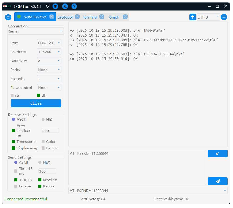 Figure 1: Example Commands
LoRa Test Waveform
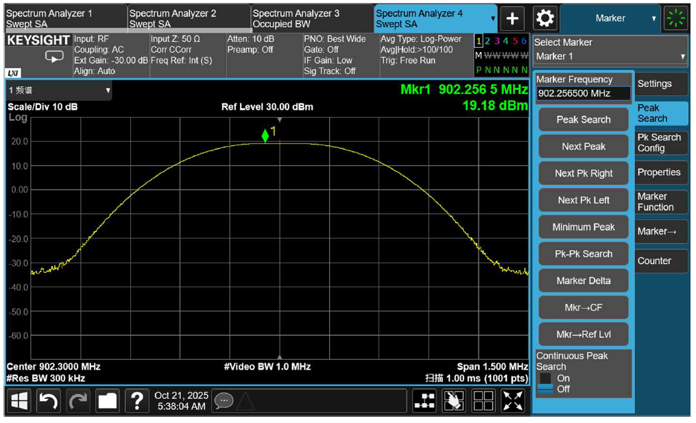 Figure 1: LoRa Test Waveform
FHSS Hopping Commands (FHSS)
Send the following commands in order, and only enter the next one after receiving OK:
| Function | AT Command |
|---|---|
| 1:Reset LoRa configuration | ATR |
| 2:Enable LoRaWAN hopping mode | AT+NWM=1 |
| 3:Set hopping band to US915 | AT+BAND=5 |
| 4:Set data rate | AT+DR=3 |
| 5:Set TX power | AT+TXP=14 |
| 6:Configure and start hopping transmission | AT+TRTH=<start_freq>:<end_freq>:<hop_step>:<hop_count> Example: AT+TRTH=902300000:914900000:200000:64 |
DR=3 corresponds to SF7, and DR=0 corresponds to SF10. TXP=14 sets the hopping power level (range 0-14).
Reference run example
Example Commands
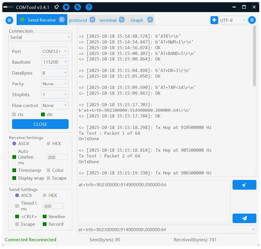 Figure 1: Example Commands
Hopping Waveform
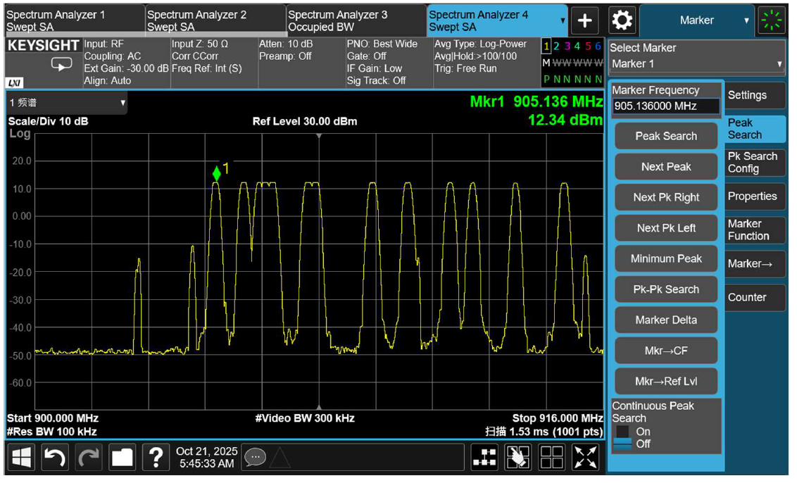 Figure 1: Hopping Waveform
Stop RF
To stop RF transmission, send the following command:
AT+TOFF
RX Test
Prepare two devices: one configured as TX and the other as RX. During testing, an interferer signal is injected to jam the receiver. The RX device should remain in its normal receiving state.
Device Command Setup
| Function | RX Device | TX Device |
|---|---|---|
| 1. Set identical operating mode | AT+NWM=0 | AT+NWM=0 |
| 2. Set identical LoRa parameters | AT+P2P=902300000:7:125:0:8:22 | AT+P2P=902300000:7:125:0:8:22 |
| 3. Continuous RX mode | AT+PRECV=65534 | |
| 4. TX packet send | AT+PSEND=11223344 |
On the TX side, enable Timed Send and set the interval to 2000 ms.
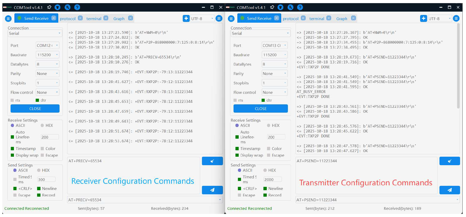 Figure 1: RX Test Commands