Gateway Management
In this section, you can manage all gateways within your organization, view their information and health status, configure WAN/LAN interfaces, manage system settings, monitor LoRaWAN communication metrics, and utilize diagnostic tools for troubleshooting.
Fleet-Level Gateway Management
This page offers a consolidated list of all gateways within the organization. You can manage them in bulk or take action on individual gateways, including direct access to their details.
To access the management console, click Gateways in the left navigation menu. You can use the search bar to find specific gateways or filter the list by Status, Location, and Columns for easier navigation.
 Figure 1: Gateways
- Current firmware: The version currently running on the gateway.
- Sent firmware: The target version sent by WisDM during an upgrade, indicating the version pending installation.
Status Indicators
| Icon | Description |
|---|---|
 | Online - The gateway is connected to the Internet and accessible through WisDM. It supports real-time operations, monitoring, and instant configuration or firmware updates. |
 | Offline - The gateway is not connected to the Internet and temporarily unavailable. Pending configurations and updates will be applied automatically once it reconnects. |
 | Provisioning - The gateway enters the provisioning status when it has an internet connection issue and cannot connect to WisDM properly. To resolve this, check and restore the internet connection. |
 | Pre-Provisioning - The gateway was added to the WisDM organization in the factory through pre-provisioning offering by RAK. |
 | Central gateway under a Location when the network server mode is set to Built-In network server. |
 | Warning indicator - Hover over the icon to view detailed warning information. |
 | Power disconnected - The gateway has lost power. Check the power supply. |
 | Update available - A newer firmware version is available for this gateway. |
 | Upgrading - A firmware upgrade is currently in progress. |
 | Firmware upgrade pending - The gateway did not upgrade successfully. |
 | Configuration mismatch - The configuration stored in WisDM (LoRaWAN settings, system settings, or network interface settings) does not match what is currently running on the gateway. |
Single Gateway Management
Operations available for an individual gateway include renaming, viewing details, assigning and unassigning, checking logs, running diagnostics, and deletion.
Rename the Gateway
You can rename a single gateway by clicking the edit icon  next to the gateway name in the Name column.
For detailed rules and requirements, see Rename Gateway.
next to the gateway name in the Name column.
For detailed rules and requirements, see Rename Gateway.
Assign a Gateway
You can assign an unassigned gateway to a target Location. Supported states for assignment:
- Online
- Offline
- Pre-provisioning
- In the actions menu, click Assign to Location.
- Select the desired Location and click Use selected location.
 Figure 1: Select a location
When selecting a Location, ensure the gateway's frequency settings match the target Location's region configuration.
- The system performs a pre-validation process (verifying frequency compatibility, identifier validity, and assignment status):
- If the gateway configuration is compatible with the target Location, it is listed under Available.
- If the configuration does not match, it is listed under Unavailable. Refer to the Status column for the specific validation result.
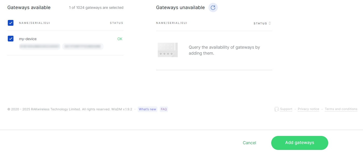 Figure 1: Adding Gateway
If the selected Location operates in Basics™ Station mode and Use individual client keys is enabled, the system displays the authentication status for the gateway. You must upload, retrieve, or skip the required credentials before proceeding.
- Click Add gateways. The gateway will then appear in the Location’s Gateways list.
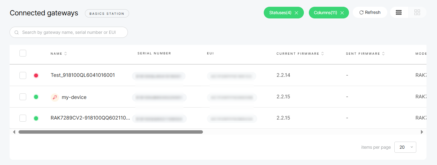 Figure 1: Gateway list
Unassign a Gateway
To remove a gateway from a location.
When unassigning a gateway:
- The gateway’s LoRaWAN configuration is reset to default values.
- Online gateways are reset immediately and remain online after the reset.
- Offline gateways are reset automatically. Once they reconnect, their status changes to Provisioning after being unassigned.
- If a gateway is in Pre-Provisioning status, the reset command is not sent.
- Keys, certificates, and tokens on the gateway are preserved for future use.
- For Built-in Network Server Locations:
- A Central Gateway cannot be unassigned while extenders are still present in the location.
- Extenders must be detached from the Central Gateway before finalizing unassignment.
- In the actions' menu, click Unassign Gateway.
- Confirm your choice in the dialog by clicking Unassign gateway.
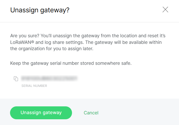 Figure 1: Confirm unassign gateway
Delete a Gateway
You can delete a gateway from the actions menu in the Gateway List. For complete rules and behavior, see Delete Gateway.
Multiple Gateway Management
Select multiple gateways from the list to apply actions in bulk. This feature is useful for large-scale operations and saves time when managing fleets.
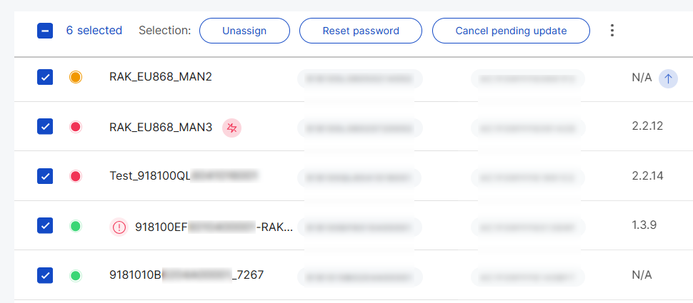 Figure 1: Manage Multiple Gateways
Unassign Gateways
For removing the gateways in bulk, follow these steps:
When unassigning a gateway:
- The gateway’s LoRaWAN configuration is reset to default values.
- Online gateways are reset immediately and remain online after the reset.
- Offline gateways are reset automatically. Once they reconnect, their status switches to Provisioning after being unassigned.
- If a gateway is in Pre-Provisioning status, the reset command is not sent.
- Keys, certificates, and tokens on the gateway are preserved for future use.
- For Built-in Network Server Locations:
- A Central Gateway cannot be unassigned while extenders are still present in the Location.
- Extenders must be detached from the Central Gateway before finalizing unassignment.
- Select multiple target gateways from the list.
- Click Unassign.
- In the confirmation dialog, confirm your selection by clicking Unassign gateways.
 Figure 1: Confirm unassign gateways
Reset Password
You can select multiple gateways in the Gateway List and reset their passwords in bulk. For rules and requirements, see Reset Gateway Password.
Synchronize System Settings
System settings are configured for each gateway. To expedite up configuration, you can synchronize system settings from a sample gateway to other selected gateways.
You can choose which settings to apply:
- Enable FOTA settings
- Time zone
- Log settings
- NTP server settings
- Select multiple target gateways from the list.
- In the actions' menu, click Synchronize system settings.
- Select the specific system settings to sync.
- Choose the sample gateway whose settings you want to copy.
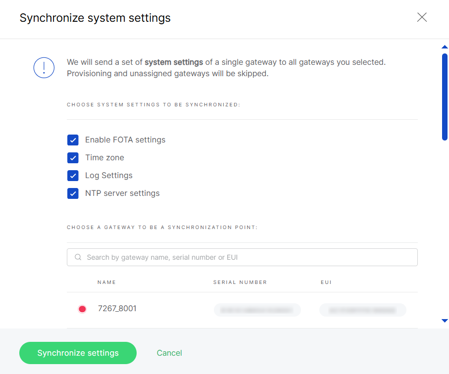 Figure 1: Synchronize system settings
- Click Synchronize settings to apply.
- Gateways in Provisioning or Unassigned states are skipped.
- Offline assigned gateways will receive the new settings the next time they come online.
Rename Gateways
You can select multiple gateways for bulk renaming. Apply a common name prefix, and WisDM will automatically append sequential numbers (e.g., MyGateway_1, MyGateway_2).
For detailed rules and requirements, see Rename Gateway.
Export Gateway Configuration Data (CSV)
Export information for the selected assigned gateways (including general info, system settings, and network interfaces) to a .csv file.
- Select multiple target gateways in the list.
- In the actions' menu, click Export CSV.
- Choose the data to include.
 Figure 1: Export CSV
- Click Export. The system will generate the file and send it to your email.
Delete Gateways
You can delete selected unassigned gateways in bulk. For complete rules and behavior, see Delete Gateway
Gateway Health & Statistics
This section presents key health indicators and performance statistics for the gateway, enabling visibility into system status and network activity.
All health indicators and statistical data in this section are synchronized from the gateway at approximately 10-minute intervals.
Gateway Overview
This section provides essential details about a single gateway, including its identity, activity, deployment, and health indicators.
Gateway Information
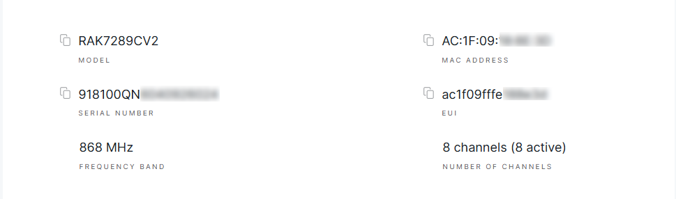 Figure 1: Device Details
- Model: The specific hardware model of the gateway (e.g., RAK7289CV2).
- EUI (Extended Unique Identifier): A globally unique identifier for the gateway, used for registration and device identification.
- MAC Address: The gateway’s network interface hardware address used for Ethernet or Wi-Fi connectivity.
- Serial Number (SN): A unique identifier assigned by the manufacturer, printed on the physical device.
- Frequency Band: The operating frequency of the gateway, inherited from the assigned LoRa Network Configuration under the gateway’s location.
- Number of LoRa Channels: The count of supported LoRa channels count (typically 8 or 16, depending on the model). The channel count determines how many simultaneous LoRaWAN connections the gateway can manage, and is a key factor in assessing its network capacity.
Traffic Statistics
This section offers a brief overview of gateway activity, highlighting the number of received packets, transmitted packets, and connected end devices. It enables you to quickly assess network load and device connectivity.
 Figure 1: Traffic Statistics
Deployment Location
WisDM allows you to visualize the physical placement of gateways on a map. The way location data is displayed depends on the status of each gateway:
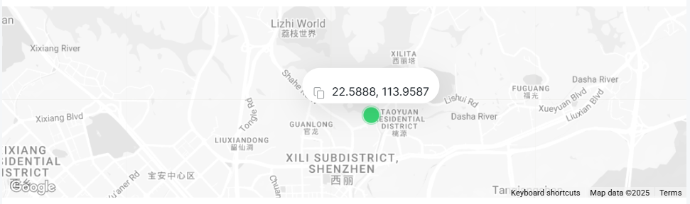 Figure 1: Gateway Deployment Location
Assigned and Online
- With GPS module: Real-time GPS coordinates are displayed on the map, refreshed approximately every 10 minutes.
- Without GPS module but with manually configured static coordinates in the gateway UI: The configured static coordinates are displayed.
- Without GPS data or manual coordinates: The system defaults to the Location Address defined in WisDM as the deployment coordinates.
Unassigned or Offline
- Offline: The map shows the last known GPS coordinates, which will not update until the gateway comes back online.
- Unassigned: Even if the gateway is online, WisDM retains and displays only the last known GPS coordinates. No further updates are collected once the gateway is removed from its Location.
SD Card Status
WisDM allows you to monitor the presence and condition of the SD card installed in the gateway.
 - SD card detected and functioning properly.
 - No SD card detected in the slot. This typically indicates that no card is inserted or that the card is loose.
 - SD card detected, but it is not functioning properly due to read/write errors.
System Performance
WisDM provides visibility into key system performance metrics for your gateway. In the Performance section, click View details to access additional information.
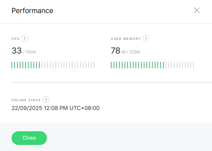 Figure 1: System Performance
-
CPU: Displays the current processing load of the gateway's CPU.
This information helps you assess the device's workload and identify potential bottlenecks. Refer to the Gateway Configuration Notifications guide for instructions on configuring alerts when usage reaches critical levels.
- Normal load: 0%-65%
- Medium load: 65%-80%
- High load: 80%-90%
- Critical load: 90%-100%
-
Used Memory: Shows how much system memory (RAM) is currently being used.
Useful for monitoring performance and detecting potential issues caused by memory saturation saturation, such as high traffic or logging. Refer to the Gateway Configuration Notifications guide for instructions on configuring alerts when usage reaches critical levels.
- Normal load: 0%-65%
- Medium load: 65%-75%
- High load: 75%-85%
- Critical load: 85%-100%
-
Online Since- Indicates the duration the gateway has been running since its last reboot.
This metrics helps monitor device stability and detect unexpected restarts.
Performance Statistics
The Performance Statistics section offers historical metrics and visual analytics of your gateway’s operation. It assists in monitoring trends, diagnosing issues, and evaluating overall performance.
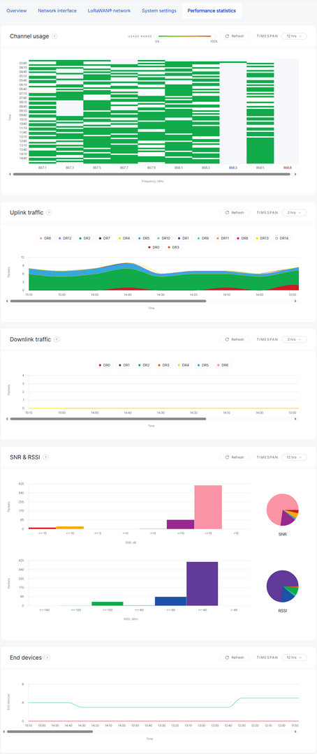 Figure 1: Performance Statistics Dashboard
- Channel Usage
Displays the frequency of each LoRa channel's occupancy within the selected time span, helping to identify congestion or uneven distribution across channels. - Uplink Traffic
Shows the volume of uplink packets over time, categorized by data rate (DR). This is useful for analyzing end-device transmission patterns. - Downlink Traffic
Tracks the number of downlink packets sent to devices, also categorized by data rate. - SNR & RSSI
Visualizes the quality and strength of received packets:- SNR (dB): Measures signal clarity.
- RSSI (dBm): Indicates signal strength.
- End Devices
Displays the number of active devices communicating with the gateway during the selected time period.
- You can adjust the time span (e.g., 2 hours, 12 hours) and refresh the charts as needed to view updated statistics as needed.
- Performance statistics are available only for online gateways and are based on historical data collected during the selected timeframe.
Solar Battery Monitoring
If your gateway supports a solar battery and is connected to it, you can monitor its status by navigating to Gateways > Select your gateway > Overview > Solar battery. The Solar battery details section will only be available only after monitoring is enabled.
Solar Battery Monitoring Setup
- In the Solar battery section, click Enable monitoring.
 Figure 1: Solar battery
- Confirm and click Enable monitoring again to activate it.
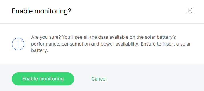 Figure 1: Confirm info
- In Solar battery details, click Refresh or Resend to apply the updates to the gateway.
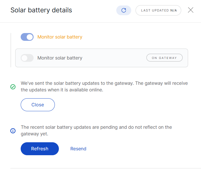 Figure 1: Apply the updates
Performance Dashboard
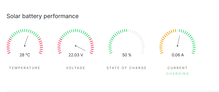 Figure 1: Solar Battery Performance
This dashboard displays live parameters of the solar battery:
- Temperature: Current operating temperature of the battery.
- Voltage: Present voltage reading of the battery.
- State of Charge (SoC): Percentage of remaining battery capacity.
- Current: Charging or discharging current.
Battery operating modes:
- Charging: The battery is currently charging.
- Fully Charged: The battery is fully charged.
- Discharging: The battery is supplying power to the gateway.
Active Events
The solar battery generates events whenever its state changes. Active events indicate ongoing issues and are categorized to assess their impact on performance:
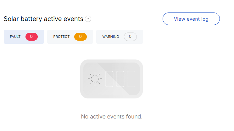 Figure 1: Active event overview
- Protect: The system detects a critical condition that could cause damage and temporarily shuts off battery power. Normal operation resumes automatically once conditions stabilize.
- Fault: The system detects potential permanent damage to the battery and recommends immediate replacement.
- Warning: The system identifies an abnormal condition that may escalate, but the gateway continues to run on battery power.
You can click View event log to access the event history. The log allows you to filter records by event type (Protect, Fault, Warning), date, and status (Unread, Read, or All).
 Figure 1: View event log
 : Click to mark the event as Read.
 : Click to mark the event as Unread.
![]() : Hover to view additional details about the event history.
: Hover to view additional details about the event history.
Battery Health
This section provides additional health and lifecycle information:
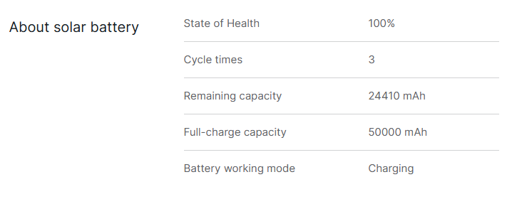 Figure 1: Battery Health
- State of Health (SoH): The overall condition of the battery compared to its original capacity.
- Cycle times: The number of full charge-discharge cycles completed.
- Remaining capacity: The current available charge in mAh.
- Full-charge capacity: The maximum charge the battery can hold when fully charged.
- Battery working mode: The current operational mode (Charging, Fully Charged, Discharging).
Network Interface Management
To ensure a stable and continuous Internet connection, WisDM gateways support multiple network interfaces through a feature called Multi-WAN. This feature allows the gateway to maintain an online presence automatically switching between available connections based on defined priorities.
Each WisDM-compatible gateway can support up to three types of Internet connections, which can be configured simultaneously:
- Ethernet: A connection provided via an Ethernet cable (default port type: WAN).
- Wi-Fi: A connection established through a wireless Wi-Fi network.
- Cellular: A connection provided via a SIM card using the cellular network (available on models equipped with a cellular module).
How Multi-WAN Works
- Automatic failover: Multi-WAN monitors all enabled interfaces and switches to the next available one if the primary connection becomes unavailable.
- Priority-based switching: The order of interfaces is user-defined, allowing control over which connection is preferred.
- High availability: The gateway remains online as long as at least one interface is active. It only goes offline when all enabled interfaces lose connectivity.
- Network interfaces are configured per gateway. However, to streamline the process and apply settings in bulk, you can use the Synchronize Network Interface Settings feature.
- Network interface status information is synchronized from the gateway at approximately 10-minute intervals.
Interface Priority
You can establish the priority order of network interfaces.
- Navigate to Gateways > Select a gateway > Network interface > WAN, then click Edit.
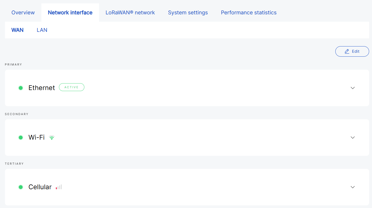 Figure 1: Network interfaces
- Use the arrows (

 ) to adjust priority.
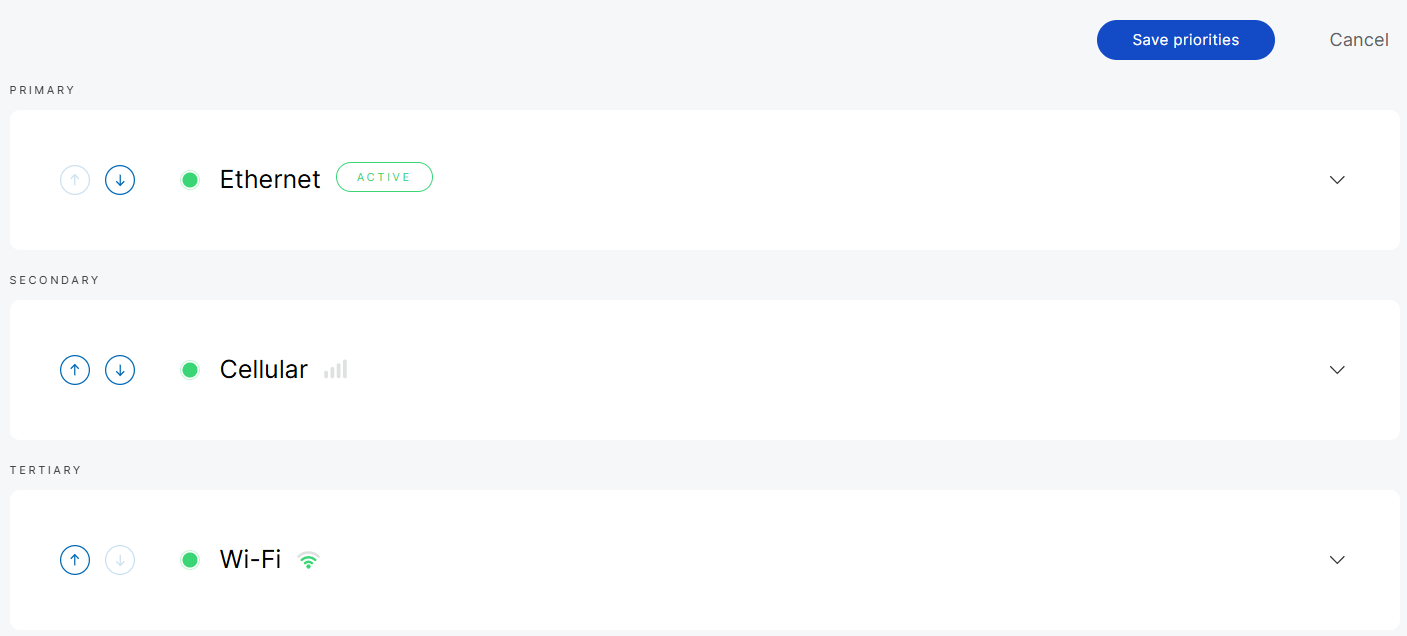 Figure 1: Configure network priorities
-
Up arrow: Increases priority.
-
Down arrow: Decreases priority.
- Click Save priorities to apply the changes. The new configuration will be sent to the gateway.
 Figure 1: Apply updates
If priority updates are not applied within 3 minutes, you can either Delete pending changes (which will keep the gateway's existing configuration) or Resend them.
WAN Interfaces�
Ethernet
- View interface details by clicking on the interface name or the arrow next to it.
 Figure 1: Ethernet details
- Protocol type: The current protocol used.
- IP Address: The IP address assigned to the gateway.
- Netmask: The network mask of the gateway.
- Connection time: The duration for which the gateway has been connected to the interface.
- Click Settings to configure the Ethernet interface.
General
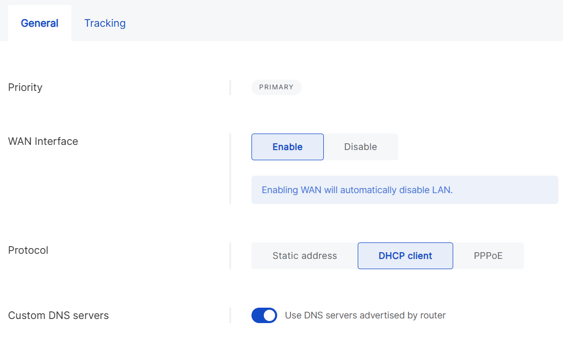 Figure 1: Ethernet general settings
- WAN Interface: Enable or disable WAN. Enabling WAN will automatically disable LAN.
- Protocol
- Static address: Manually configure the IP address, netmask, router, and DNS servers.
- DHCP client: Automatically obtain IP configuration from the router’s DHCP server.
- PPPoE: Configure Point-to-Point Protocol over Ethernet with the username and password provided by your ISP.
- Use DNS servers advertised by router: Enable this to use DNS from the router. If you want to use a custom DNS server, you need to disable this option.
- DNS Server: Add custom DNS servers.
Tracking
Tracking monitors connectivity through periodic tests. If an interface becomes unstable, the gateway fails over to another connection and will switch back once stability is restored, provided that connection has higher a priority.
- Type
- ICMP: Uses ping requests to verify reachability (e.g., 8.8.8.8).
- HTTP: Uses HTTP requests to check if a target website is reachable.
- Target address: IP address for the ICMP tracking method or domain name/URL for HTTP.
- Reliability: Minimum number of addresses that must respond to confirm a successful ping.
- Ping count: Number of ping packets sent per test.
- Ping timeout (seconds): Maximum time to wait for a ping response.
- Ping interval: Time interval between each health check cycle.
- Down: Number of consecutive failed attempts required to mark the interface as Down.
- Up: Number of consecutive successful attempts required to mark the interface as Up again.
Wi-Fi
- View interface details by clicking on the interface name or the arrow next to it.
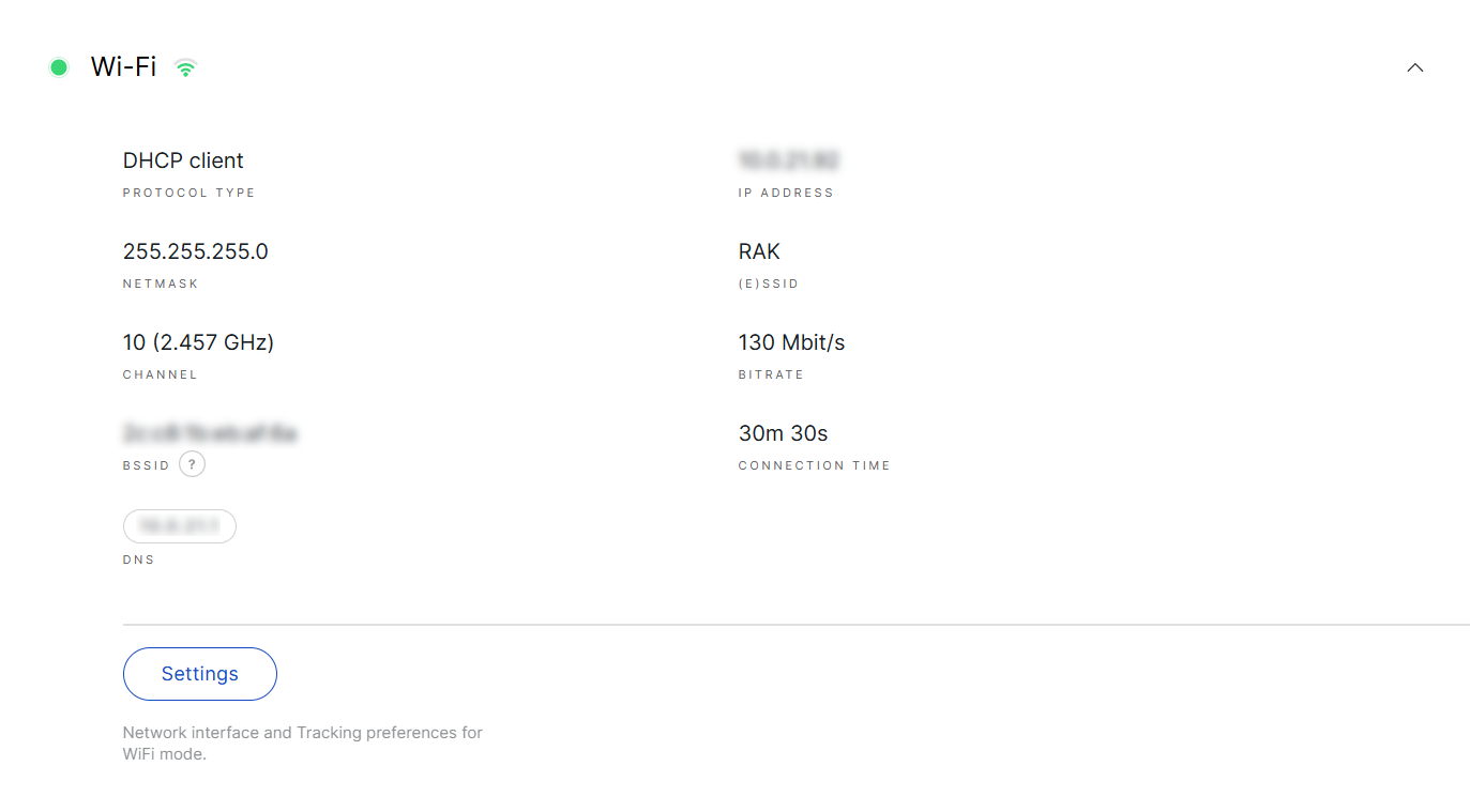 Figure 1: WiFi details
- Protocol Type: The current protocol used.
- IP Address: The IP address assigned to the gateway.
- Netmask: The netmask assigned to the gateway.
- (E)SSID: The SSID of the Wi-Fi network.
- Channel: The operating frequency of the Wi-Fi network.
- Bitrate: The bitrate of the Wi-Fi network.
- BSSID: The MAC address of the Wi-Fi access point or router.
- Connection time: The duration the gateway has been connected to the Wi-Fi interface.
- DNS: DNS server address.
- Click Settings to configure the Wi-Fi interface.
General
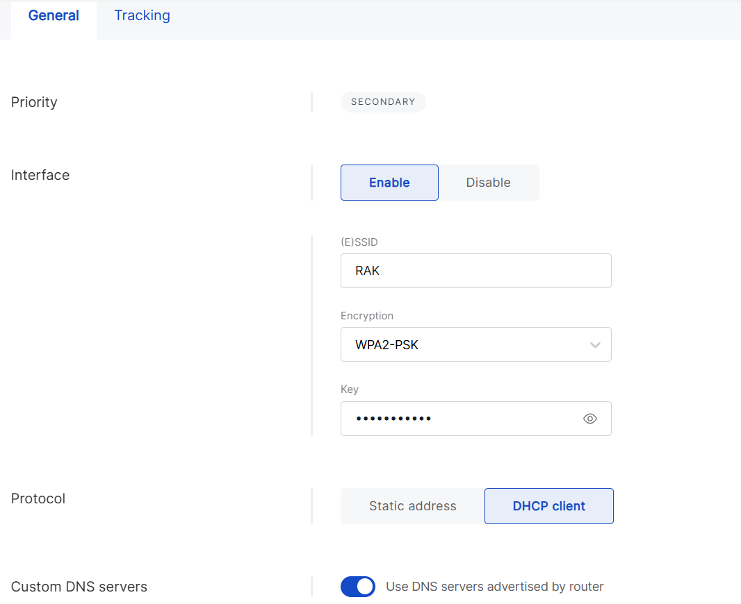 Figure 1: Wi-Fi general settings
- Enabled/Disabled: Enable or disable the Wi-Fi interface.
- Available (E)SSID networks: Scan for available Wi-Fi networks, select one, or manually enter the details.
- (E)SSID: Extended Service Set Identifier.
- Encryption: Select the type of encryption used by the network and enter the password. Options include No Encryption, WPA-PSK, WPA2-PSK, and WPA-PSK/WPA2-PSK Mixed Mode (recommended).
- Protocol
- Static address: Manually configure the IP address, netmask, router, and DNS servers.
- DHCP client: Automatically obtain IP configuration from the router's DHCP server.
- Use DNS servers advertised by router: Enable this option to use the DNS servers provided by the router. If you prefer to use a custom DNS server, you must disable this option.
- DNS Server: Add custom DNS servers.
Tracking
Tracking monitors connectivity trough periodic tests. If an interface becomes unstable, the gateway fails over to another connection and switches back once stability is restored, as long as the original connection has a higher priority.
- Type
- ICMP: Uses ping requests to verify reachability (e.g., 8.8.8.8).
- HTTP: Uses HTTP requests to check if a target website is reachable.
- Target address: IP address for the ICMP tracking method or domain name/URL for HTTP.
- Reliability: Defines the minimum number of responses needed to confirm a successful ping.
- Ping count: Number of ping packets sent per test.
- Ping timeout (seconds): Maximum time to wait for a ping response.
- Ping interval: Time interval between each health check cycle.
- Down: Number of consecutive failed attempts required to mark the interface as Down.
- Up: Number of consecutive successful attempts required to mark the interface as Up again.
Cellular
- View interface details by clicking on the interface name or the arrow next to it.
 Figure 1: Cellular details
- IP Address: The IP assigned to the gateway.
- Netmask: The netmask assigned to the gateway.
- IMSI: International Mobile Subscriber Identity.
- ICCID: Integrated Circuit Card Identifier.
- Connection time: The duration for which the gateway has been connected to the interface.
- IMEI: International Mobile Equipment Identity.
- Network: The cellular network standard.
- DNS: DNS server address.
- RSRP: Reference Signal Received Power, indicating the strength of the received LTE reference signal.
- RSSI: Received Signal Strength Indicator, representing the total received signal power, including interference and noise.
- RSRQ: Reference Signal Received Quality, reflecting signal quality by considering both interference and signal strength.
- SINR: Signal-to-Interference-and-Noise Ratio, measuring signal quality relative to background noise.
- RAT: Radio Access Technology, indicating the wireless technology in use.
- SIM Card Status: The status of the SIM card.
- Click Settings to configure the cellular interface.
General
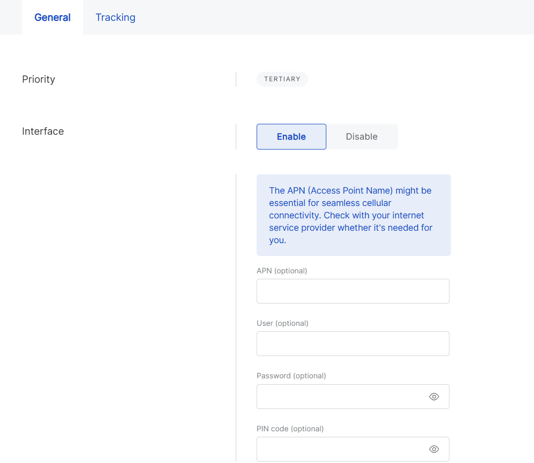 Figure 1: Cellular general settings
- Enabled/Disabled: Toggle the cellular interface on or off.
- APN (optional): Enter the Access Point Name for the connection.
- User (optional): Specify the username for authentication (leave blank if not required).
- Password (optional): Enter the password for authentication (leave blank if not required).
- PIN code (optional): Enter the SIM card's PIN code (leave blank if not required).
Tracking
Tracking monitors connectivity through periodic tests. If an interface becomes unstable, the gateway will switch to another connection and revert to the original once stability is restored, provided it has a higher priority.
- Type
- ICMP: Uses ping requests to verify reachability (e.g., 8.8.8.8).
- HTTP: Uses HTTP requests to check if a target website is reachable.
- Target address: IP for the ICMP tracking method or domain name/URL for HTTP.
- Reliability: Defines the minimum number of addresses that must respond to confirm a successful ping.
- Ping count: Number of ping packets sent per test.
- Ping timeout (seconds): Maximum time to wait for a ping response.
- Ping interval: Time interval between each health check cycle.
- Down: Number of consecutive failed attempts required to mark the interface as Down.
- Up: Number of consecutive successful attempts required to mark the interface as Up again.
LAN Interfaces
In addition to its connection to the internet (WAN group of settings), the gateway can share a connection with nearby devices.
Ethernet
The same Ethernet port can be configured for either WAN or LAN. In WAN mode, the gateway acts as a client to connect to the internet. In LAN mode, it acts as a server, providing network access to connected devices. The port cannot function as both simultaneously.
- View interface details by clicking on the interface name or the arrow next to it.
 Figure 1: Ethernet
- Click Settings to configure the LAN ethernet interface.
 Figure 1: Ethernet settings
-
Enabled/Disabled: Enable or disable the LAN Ethernet interface.
NOTEEnabling Ethernet LAN may result in the loss of the gateway's internet connection, which could trigger a rollback operation if no other interfaces are functioning.
Wi-Fi
Wi-Fi is another interface for providing local area network access. When LAN Wi-Fi is activated, the gateway functions as an access point, allowing nearby devices to connect.
- View interface details by clicking on the interface name or the arrow next to it.
 Figure 1: Wi-Fi
- Click Settings to configure the LAN Wi-Fi interface.
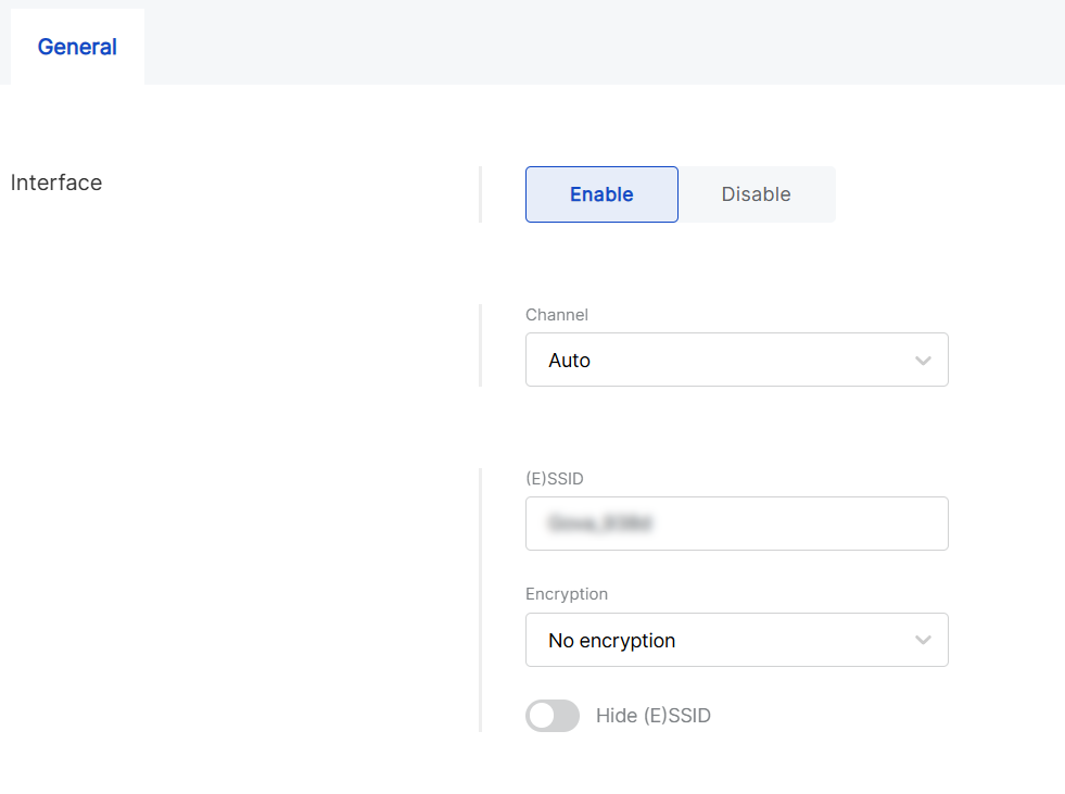 Figure 1: Wi-Fi settings
- Enabled/Disabled: Toggle the Wi-Fi LAN interface on or off.
- Channel: Configure the Wi-Fi channel. The default setting is Auto, which allows the gateway to select the optimal channel automatically.
- (E)SSID: Specify the SSID for the wireless access point (AP).
- Encryption: Choose the encryption type for the Wi-Fi AP. Options include No Encryption, WPA-PSK, WPA2-PSK, and WPA-PSK/WPA2-PSK Mixed Mode
- Hidden: Enable this option to conceal the SSID, making the AP invisible to devices searching for networks.
DHCP Server
For LAN interfaces, you can configure the DHCP server settings. By default, the gateway runs a built-in DHCP server that assigns IP addresses to connected devices, but you can adjust these settings as needed.
- To view the DHCP server details, click on the interface name or the arrow next to it.
 Figure 1: DHCP Server
- Click Settings to modify the configuration.
 Figure 1: DHCP Server settings
LoRaWAN Network
In WisDM, each gateway inherits its LoRaWAN configuration from the location it is assigned to. This means you cannot configure LoRaWAN parameters directly on an individual gateway.
However, the application of these settings unique to each gateway, which may result in differing configuration states. In the LoRaWAN Network of a gateway, you can view both the values inherited from the Location and their current status, whether they have already been applied or are still pending.
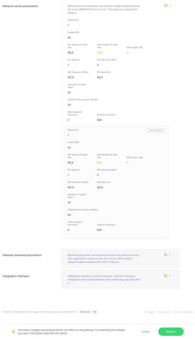 Figure 1: Updates pending
As illustrated in the example:
- The Location configuration specifies
Max allowed TX data rate = DR_5andADR margin = 5. - The Gateway configuration (current state on the device) still shows
Max allowed TX data rate = DR_7andADR margin = 9.
This indicates that the gateway has not yet applied the latest Location settings, resulting in a pending state.
WisDM highlights such mismatches with a warning icon . When a mismatch occurs, you can:
- View configuration differences: Examine which parameters differ between the Location settings and the gateway’s current values.
- Decide whether to apply the Location configuration (click Resend) or keep the gateway’s current configuration (click Delete pending changes).
When a gateway operates in Basics™ Station mode with Use individual client keys enabled, the certificate, client key, and token fields become configurable. This enables per-gateway authentication even within the same Location.
System Settings
This section describes how to configure general settings for an individual gateway.
Rename Gateway
Gateways can be renamed in WisDM for easier identification. WisDM supports both single gateway rename and bulk rename.
- Single gateway rename: This option is available from System Settings or the Gateway List.
- Bulk rename: This option is available only from the Gateway List.
- A new name is displayed immediately in WisDM, but the actual update remains pending until the gateway comes online.
- Renaming is not supported for gateways in Provisioning status.
- For bulk renaming, you can assign a common prefix and WisDM will automatically append sequential numbers (e.g.,
MyGateway_1,MyGateway_2, …).
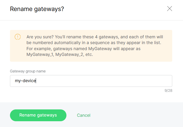 Figure 1: Rename Gateway Example
Timezone Settings
The gateway timezone determines the timestamps for events generated by the gateway. You can update the timezone at any time in System Settings. Changes remain pending until the gateway is online.
- For accurate timekeeping, you can configure NTP servers for automatic synchronization.
- To adjust the timezone for all gateways in bulk, see Synchronize system settings.
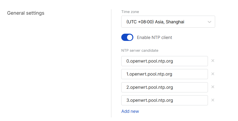 Figure 1: Timezone settings
Reset Gateway Password
Gateways allow for the remote resetting of their local password (WisGateOS root password) through WisDM. This operation is security-sensitive and requires proper authentication.
WisDM offers two options for password reset: single gateway password reset and bulk password reset.
- Single gateway reset: This option is available from System Settings.
- Bulk password reset: This option is available from the Gateway List.
-
Two-factor authentication (2FA) must be enabled in your RAK ID security settings.
-
Password resets are only available for online gateways.
-
During a bulk reset, if the selection includes both online and offline gateways, WisDM will reset the password only for the online gateways, while the offline ones will be skipped.
-
New passwords are never stored in WisDM, they are delivered securely to the gateways.
- Click Reset password.
 Figure 1: Reset Password
- Enter a new password that meets the following requirements:
- At least 12 characters
- At least one special character
- At least one number
- At least one Latin letter
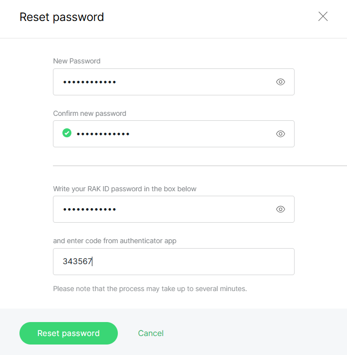 Figure 1: Configure password
- Click Reset password to apply the change.
Log Settings
The Log Settings section defines how gateway logs are stored locally and whether they are shared externally.
 Figure 1: Log settings
- File rotation cycle: Defines the duration for which log files are stored locally on the gateway before being overwritten.
- Share logs
- None: Logs remain solely on the gateway.
- External server: Logs are sent to an external server, requiring configuration of the server's IP address and port.
- WisDM: Logs are uploaded to the WisDM cloud platform.
- WisDM log retrieval cycle: Specifies how frequently the gateway uploads logs to WisDM, synchronized with the gateway.
- WisDM log rotation cycle: Indicates how long WisDM retains logs before deletion them (applies only on the WisDM side).
- Both external server and WisDM: Logs are shared with both an external server and WisDM.
- Once log sharing to WisDM is enabled, you can view uploaded files in History log.
- Uploading logs, particularly over cellular connections, may increase data usage.
Delete Gateway
You can permanently remove a gateway from WisDM. WisDM supports both single gateway deletion and bulk deletion.
- Deleting a gateway will reset it to factory defaults.
- All related data will be permanently erased from the organization.
- This action cannot be undone; the gateway must be re-added and reconfigured if needed again.
Single gateway deletion: Available from System Settings or the Gateway List. Bulk deletion: Available only from the Gateway List. Gateway Deletion Reference
- WisDM only deletes unassigned gateways.
- Single gateway deletion
- If the selected gateway is assigned, WisDM automatically unassigns it before deleting it.
- Bulk deletion
- Only gateways that are already unassigned will be deleted.
- If the selection includes assigned gateways, they are skipped automatically.
- In all cases, deletion resets the gateway to factory defaults and permanently removes all related data from WisDM.
Single Gateway Firmware Update
Firmware is the internal software that controls the operation of the gateway. To ensure stability and security, it is strongly recommended to keep all gateways updated with the latest version available for their model.
Each gateway’s firmware can be updated individually from its System Settings page. This method is ideal for updating a single device, testing a specific version, or troubleshooting before deploying a bulk upgrade at the location level.
Check Current Firmware
You can check your gateway’s current firmware version on either the Gateway Overview page or in System Settings.
- Gateway Overview Page
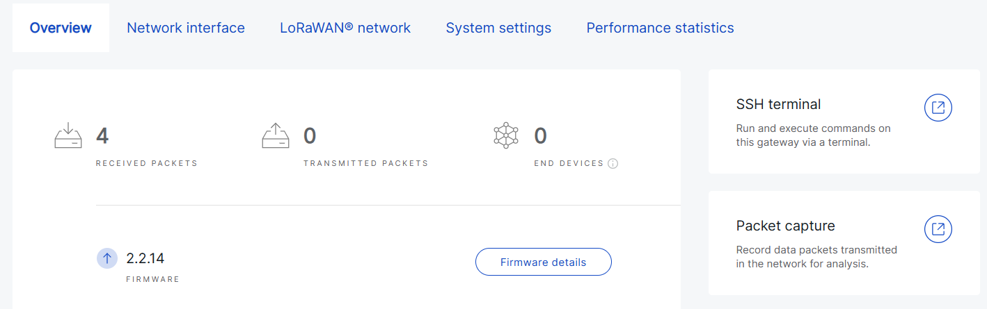 Figure 1: Firmware information from Gateway Overview
- System Settings
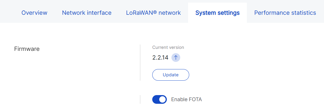 Figure 1: Firmware information from System Settings
If a newer firmware version is available, WisDM automatically displays an update prompt with the icon.
Upgrade Steps
- Before performing the upgrade, ensure that FOTA is enabled for the gateway.
- Verify that the gateway is powered by a stable power supply.
- The gateway will reboot during the update, which may cause brief service interruptions.
- Go to Gateways > Select a gateway > System Settings.
Figure 1: Gateway firmware- Click Update.
- Choose the desired firmware version and click Send updates.
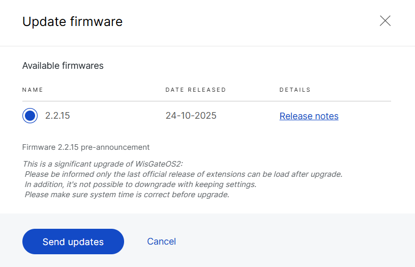 Figure 1: Choose firmware version for the gateway
The following types of firmware may be available:
- Official releases - Stable production versions.
- Critical updates - These contain security patches or essential fixes. When auto-updates are enabled at the location level, they are applied automatically across all gateways. Otherwise, they will be listed here for manual upgrade.
- Beta versions - Offered for testing or early access and marked with a special icon. Install only under the guidance of the RAK Support Team. They are not recommended for production use unless explicitly directed.
- After initiating the update, WisDM displays the current upgrade status for the gateway:
- In progress - The update is currently being applied.
 Figure 1: In progress
-
Pending - The gateway is currently offline. The update is queued and will start automatically once the gateway reconnects to WisDM.
You can cancel the pending update before it begins by clicking Cancel pending update in the Firmware section.
 Figure 1: Pending
In addition to upgrading a single gateway, WisDM also supports bulk firmware upgrades for all gateways within a location, as well as automatic critical updates.
For details, see Location Management > Bulk Firmware Updates.
Diagnostic & Debug
View Real-Time Log
You can view real-time logs for both assigned and unassigned gateways, which is useful for monitoring system processes and diagnosing immediate issues. This feature is available only when the gateway is online.
You can open the log viewer from:
- Gateway Overview page
 Figure 1: Access Real-Time Logs from Gateway Overview
- Gateway List
 Figure 1: Access Real-Time Logs from Gateway List
- Click View log.
- In the pop-up window, enter the gateway access password and click Sign in.
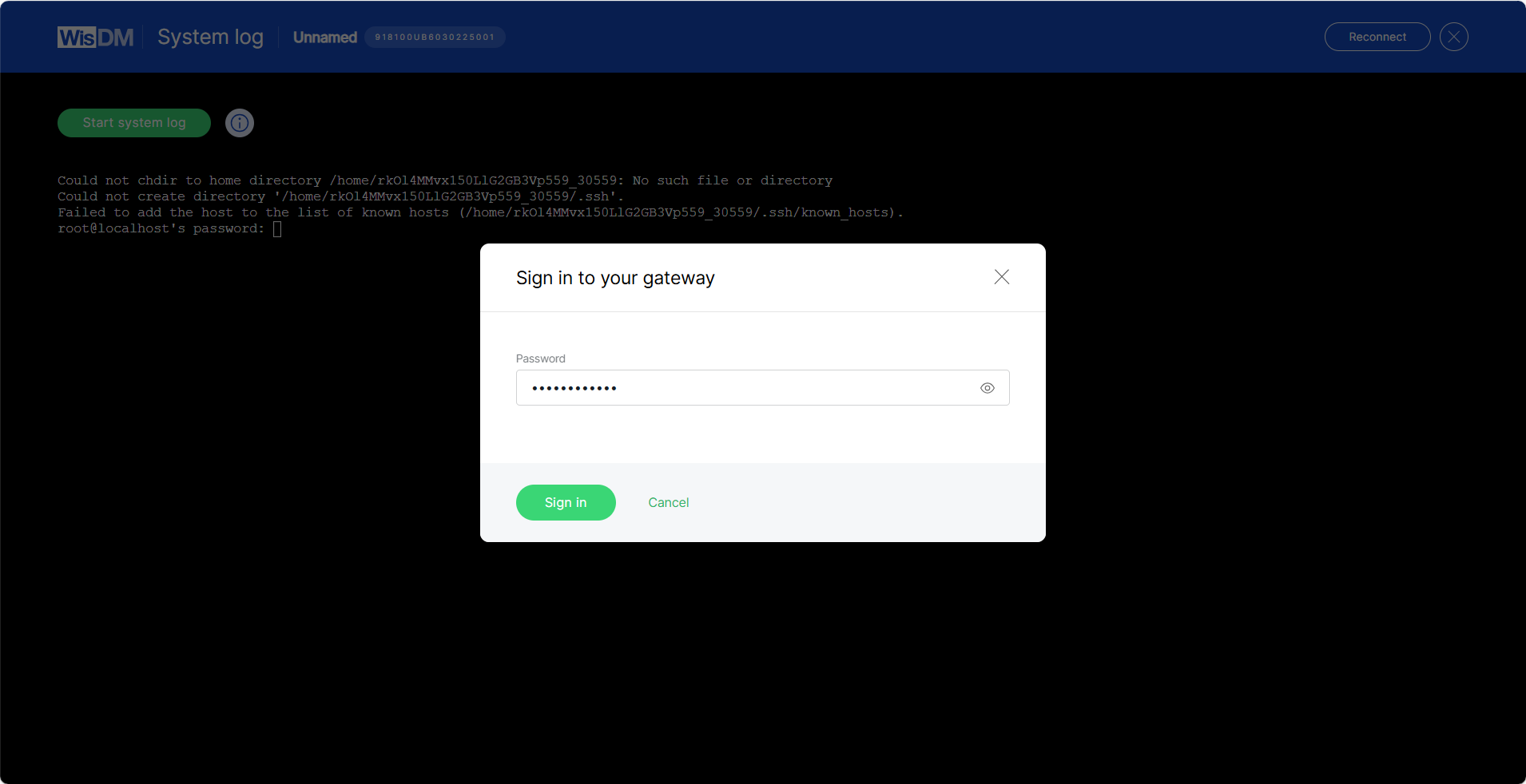 Figure 1: Sign in to Your Gateway
- Click Start system log. WisDM will automatically send the command
logread -fto the gateway, and log entries will begin updating in real time.
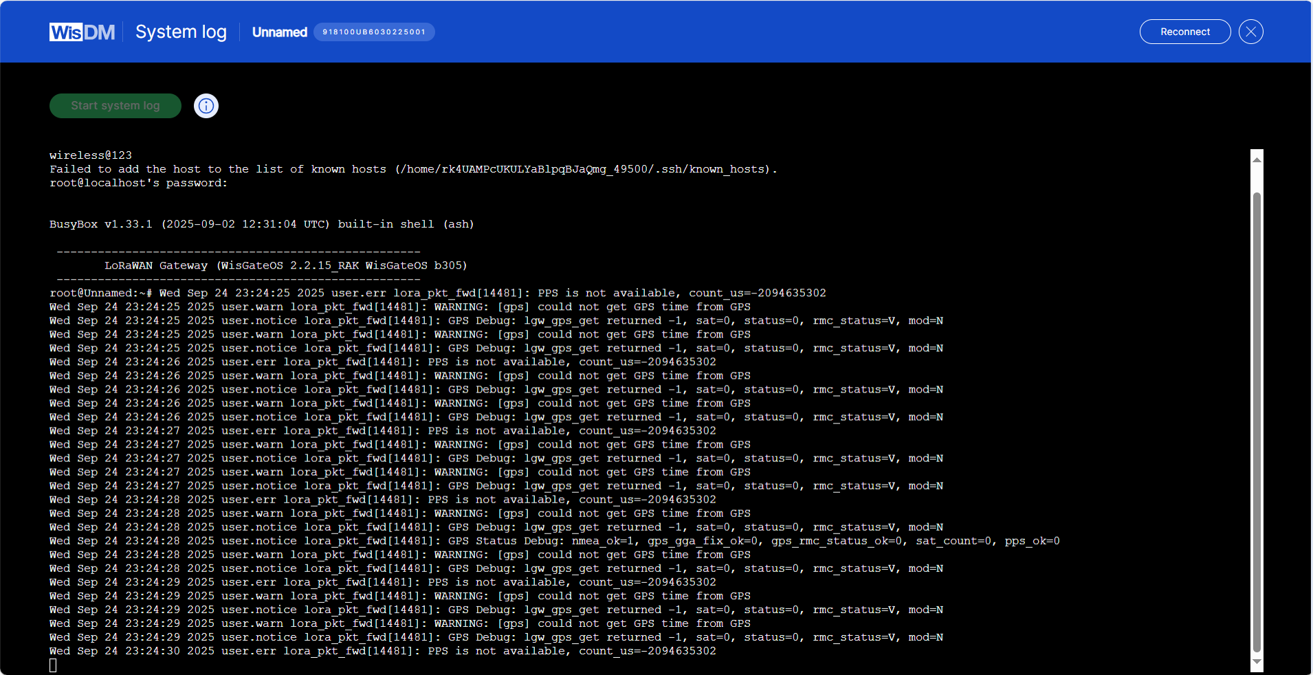 Figure 1: View Real-Time Log
- (Optional) To pause log updates, press Ctrl+C.
History Log
If you have enabled log sharing with WisDM in the gateway's System Settings > Log Settings, WisDM allows you to view the gateway’s historical system logs for the period specified in your configuration.
- Navigate to Gateways > Select a gateway > Overview.
Figure 1: Access History Logs from Gateway Overview- Click History log. Use the Filters panel to select a specific time period and view the logs for that range.
 Figure 1: Filter and Review History Logs
You can review all logs available within the WisDM log rotation cycle.
SSH
Administrators can use SSH to perform advanced tasks such as maintenance, diagnostics, running custom scripts, installing firmware components, and other operations.
Access is granted through a secure Linux SSH tunnel to a specific gateway, provided that the gateway is online.
Only one SSH session can run on a gateway at a time. If a new session is requested while another is active, the existing session will be terminated and replaced with the new one.
Access SSH
You can access the SSH terminal from either of these entry points:
- Gateway Overview page
Figure 1: SSH Access from Gateway Overview- Gateway List
Figure 1: SSH Access from Gateway ListStart an SSH Session
- Click SSH terminal.
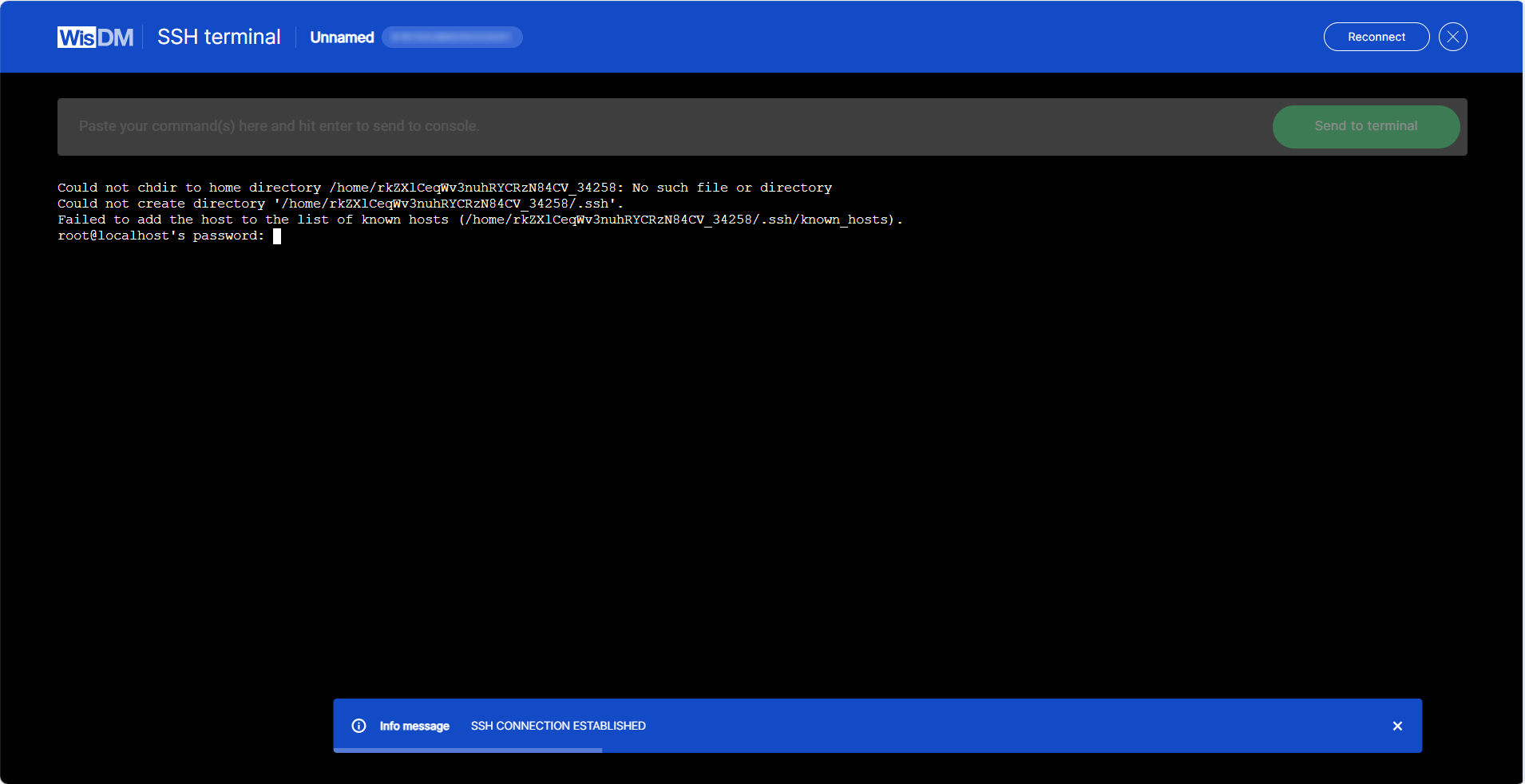 Figure 1: Open SSH Terminal
- Enter the gateway password to authenticate.
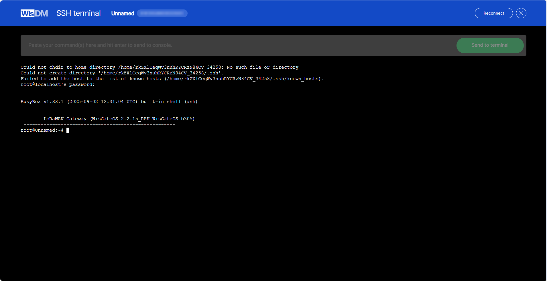 Figure 1: Log in to SSH Terminal
- After logging in, you can execute diagnostic commands, perform maintenance tasks, or run other supported Linux shell commands directly on the gateway.
If you cannot establish an SSH connection, check your firewall settings. By default, WisDM opens SSH sessions using EU IP addresses. If these IPs are not whitelisted in your firewall, the SSH session may fail.
Packet capture
Gateway packet capture is a collection of packet entries reported by the gateway, detailing the packets it receives and transmits. This feature aids in researching and troubleshooting potential data exchange or connectivity issues in IoT networks centered around the gateway.
This feature is available only when the gateway is online.
Access Packet Capture
You can access the Packet Capture feature from two entry points:
- Gateway Overview page
Figure 1: Access from Gateway Overview- Gateway List
Figure 1: Access from Gateway ListStart a Session
-
Click Packet capture or Open packet capture.
-
Select the session duration and click Start new session.
 Figure 1: Set Session Duration
- The interface displays the list of packets transmitted and received by the gateway in real time.
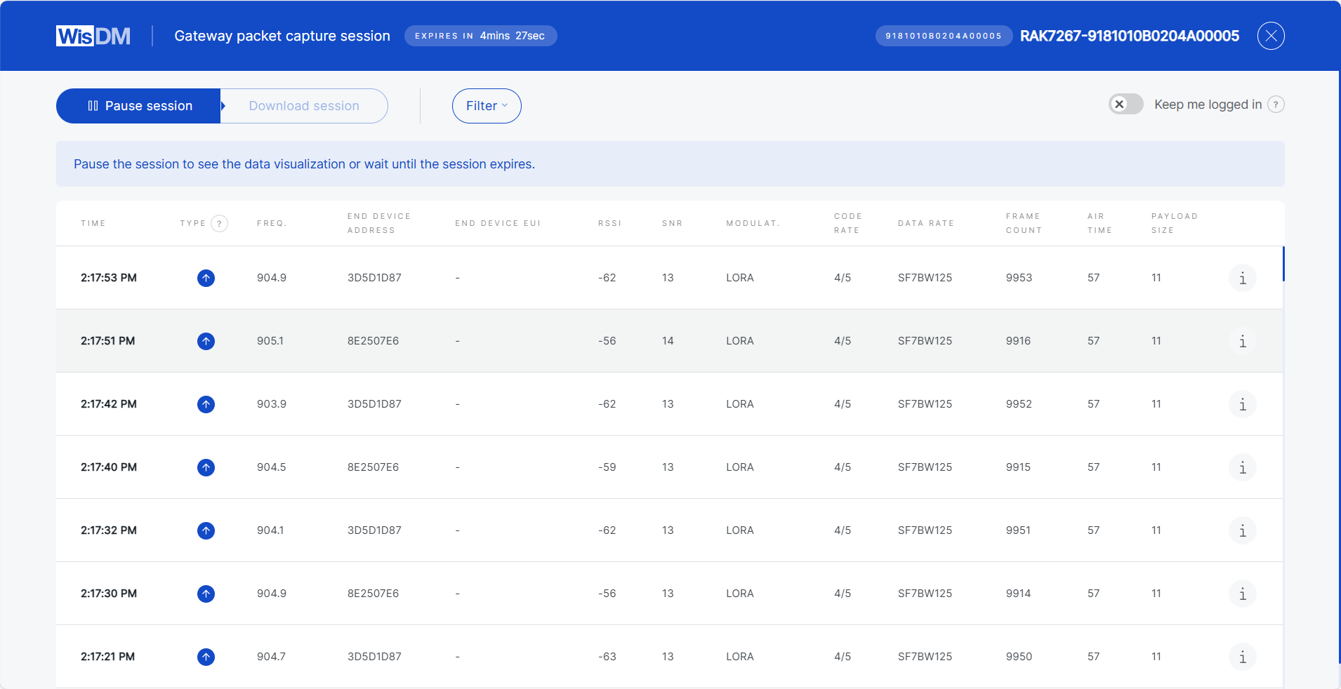 Figure 1: Packets Overview
- When the session ends, you can either start a new session with a different duration or download the captured data for further analysis.
Packet Details
When you click a packet entry in the Packet Capture session, WisDM displays detailed information about the packet. This information helps you analyze connectivity quality, packet integrity, and device activity.
 Figure 1: Packet Details
| Field | Description |
|---|---|
| Time | Timestamp of when the gateway received the packet. |
| Type | Packet type, such as Confirmed Data Up, Join Request, Join Accept. |
| Frequency | Radio frequency used for transmitting the packet. |
| End Device Address (DevAddr) | 32-bit short address of the device within the LoRaWAN network. |
| End Device EUI (DevEUI) | A globally unique 64-bit identifier assigned to the end device by the manufacturer. |
| Application EUI (AppEUI / JoinEUI) | A globally unique identifier of the application. Used in the join procedure to associate the device with an application server. |
| RSSI | Received Signal Strength Indicator at the gateway (in dBm). Higher (closer to 0) indicate stronger signals. |
| SNR | Signal-to-Noise Ratio (in dB). Higher values indicate better signal quality. |
| Modulation | Transmission modulation type. |
| Code Rate | Forward error correction scheme applied to the transmission. |
| Data Rate | Spreading factor and bandwidth utilized in the transmission. |
| Frame Count (FCnt) | Incremental counter provided by the device, useful for detecting lost or duplicate frames. |
| Air Time | Time taken for the packet to be transmitted over the air. |
| Payload Size | Size of the packet payload in bytes. |
| CRC Status | Result of the CRC integrity check. CRC_OK indicates that the packet passed validation. |
| MAC Command | If present, shows any MAC command carried within the frame. |
| Tx Power | Transmission power level used by the end device (in dBm), if available. |
| Original Log Object | Gateway log entry formatted in JSON. |
| LoRaMAC Data Frame | Parsed LoRaWAN MAC frame. |
Additional Operations
Join Session
If the selected gateway already has an active session, you can join it for the specified duration. When joining, you may also request to load all previously captured packets from the beginning of that session.
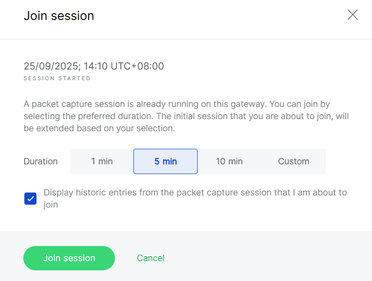 Figure 1: Join Existing Session
Pause and Resume
You can pause/resume updates at any time. While paused, you can review older packets or apply filters by packet parameters.
 Figure 1: Pause and Resume
Packet Capture Statistics
When a packet capture session is paused or finished, WisDM generates statistics to summarize gateway and end-device activity.
 Figure 1: Packet Capture Statistics
Keep Me Logged In
For security reasons, WisDM automatically logs you out after 15 minutes of inactivity.
If your packet capture session lasts longer than 15 minutes, ensure that you enable the Keep me logged in toggle during the session to avoid interruption.