WisDM Quick Start Guide
This guide helps you complete the basic setup required to bring your first gateway online in WisDM.
By the end of this guide, you will be able to:
- Sign in to WisDM with a RAK ID.
- Create an Organization.
- Create a Location.
- Select a LoRaWAN® network mode.
- Add a gateway to the Location.
- Confirm that the gateway is online.
Before You Start
Before you start, make sure you have:
- A RAK ID account. If you do not have one, click RAK ID Portal to create a new account.
- The gateway Serial Number and Gateway EUI.
- A RAK gateway running WisGateOS 1.2.2 or later. The latest firmware version is recommended.
- WisDM integration is enabled on the gateway.
- Internet access for the gateway.
Sign in to WisDM
To use WisDM, you must sign in with a RAK ID account.
-
Go to the WisDM platform.
-
Click Sign in with RAK ID.
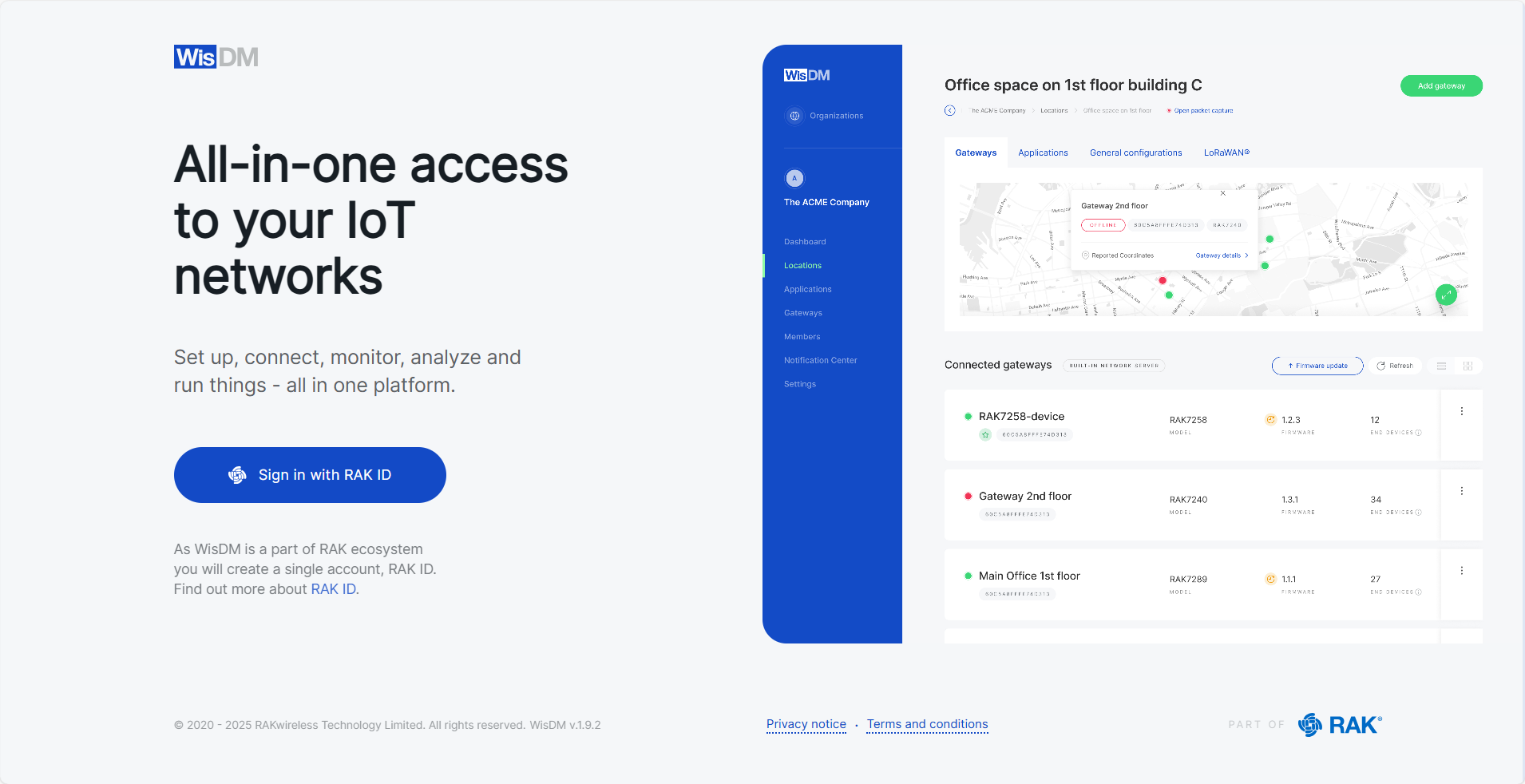 Figure 1: Accessing WisDM
- If you already have a RAK ID, see Sign in with an Existing RAK ID.
- If you do not have a RAK ID, see Create a New RAK ID.
Sign in with an Existing RAK ID
- Enter your RAK ID credentials.
- Click Sign in.
 Figure 1: Login to WisDM
After successful sign-in, you will be directed to the Organizations page.
Create a New RAK ID
If you do not have a RAK ID, you can create one during the WisDM sign-in process.
-
Click Create new.
-
Enter your registration details.
 Figure 1: Create RAK ID
 -
Check your email inbox for the verification code, then enter it.
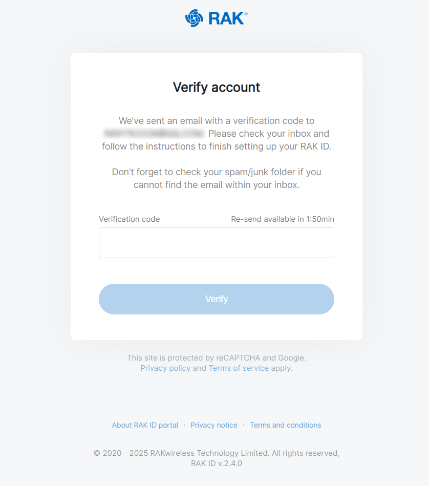 Figure 1: Verify Account
 -
Read and accept the Terms and Conditions.
-
After completing registration, click New Organization, and you will be redirected to the Organizations page.
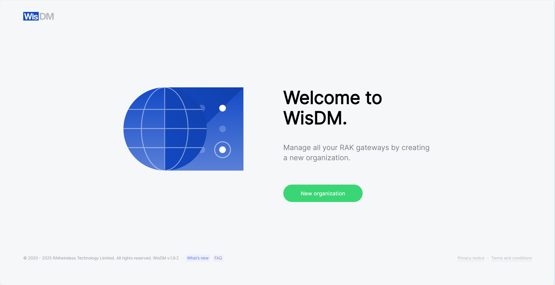 Figure 1: Organizations
Create an Organization
An Organization is the top-level workspace in WisDM. It groups your Locations, gateways, users, subscriptions, and organization-level settings.
- On the Organizations page, click New organization.
- Enter your organization's registration details and click Next.
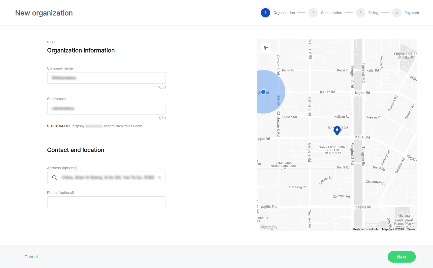 Figure 1: Create an organization
-
Company name: Enter a name, up to 50 characters.
-
Subdomain: Automatically generated based on the company name and can be customized.
-
Address (optional): Add an address by typing in the search box or selecting a location on the map.
-
Phone (optional): Optionally, provide a contact phone number.
- Select a subscription plan. For this quick start, select Community (Free) as an example. The Community plan is suitable for small deployments, proof of concept, and testing, and allows you to quickly create an Organization and start adding gateways.
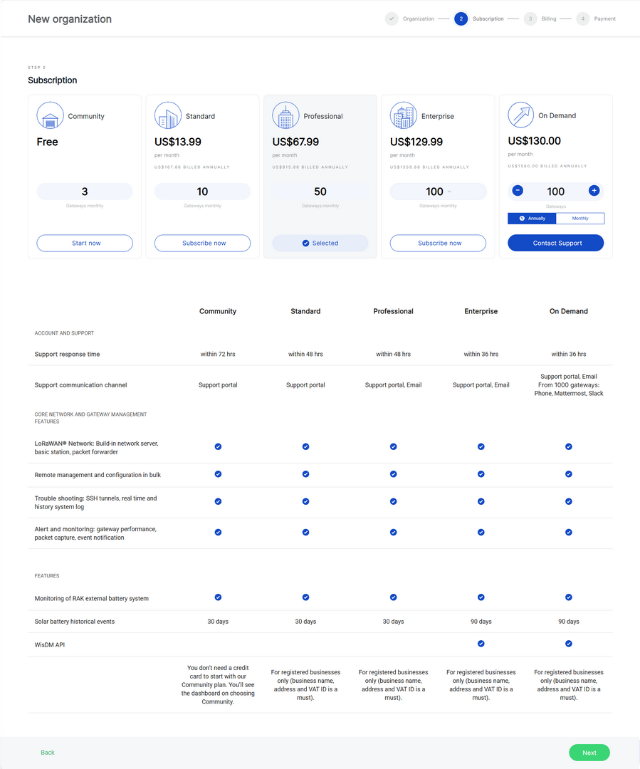 Figure 1: Subscription Plan
- Community (Free): This subscription is free and allows for up to 3 gateways. It is designed for small deployments, DIY projects, proof of concept (POC), and testing purposes.
- Standard: The Standard subscription supports flexible gateway tiers, allowing you to scale from 4 up to 40 gateways, making it suitable for small to medium-sized deployments.
- Professional: The Professional subscription supports multiple gateway tiers, typically ranging from 41 to 90 gateways, making it suitable for medium-sized deployments, system integrators, and solution providers.
- Enterprise: The Enterprise subscription supports large-scale deployments with flexible gateway tiers ranging from 91 up to 1000 gateways. This plan is designed for extensive deployments and enables centralized remote management of many gateways.
- On Demand: A flexible subscription for custom deployments, supporting more than 100 gateways. Users can choose between monthly or annual billing. For setup, please contact support.
Other subscription plans are available for larger deployments or custom requirements. For more information about subscription plans, billing, invoices, and plan changes, see Create an Organization.
- Click Start now, and then click Next to continue.
Create a Location
A Location is a logical or physical deployment area where gateways are grouped and managed together. Gateways assigned to the same Location inherit Location-level LoRaWAN network settings.
To create a Location:
-
Go to Locations.
-
Click New location.
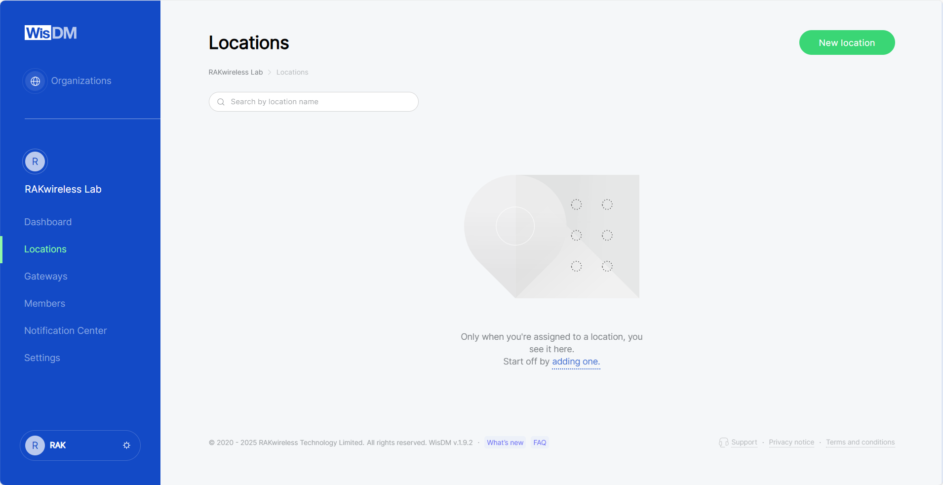 Figure 1: Locations tab
 -
Enter the location details and click Save location.
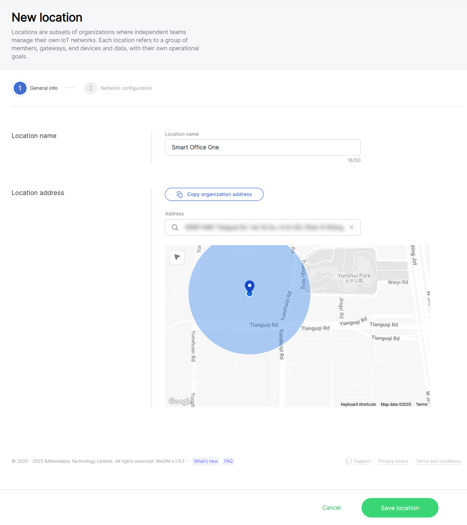 Figure 1: General information
- Location name: Choose a name of your choice, up to 50 characters.
- Location address: Either use the organization's address or provide a new one using the search bar or map.
-
Continue to the LoRaWAN network configuration.
Choose a LoRaWAN Network Mode
WisDM supports different LoRaWAN network modes. Choose the mode based on how your gateways connect to the LoRaWAN Network Server.
| Mode | Use This Mode When | Typical Use Case |
|---|---|---|
| Packet Forwarder | You already have an external LoRaWAN Network Server that supports UDP Packet Forwarder or MQTT Bridge. | ChirpStack or other external LNS deployments. |
| Basics™ Station | You want a more secure connection to an external LNS using CUPS/LNS and certificates or tokens. | Secure production deployments with external LNS. |
| Built-in Network Server | You want the gateway to run the LoRaWAN Network Server locally without relying on an external LNS. | Quick pilots, local deployments, or edge networks. |
This quick start uses Built-in Network Server only as an example setup path to demonstrate the basic gateway onboarding flow.
If your deployment already uses an external LoRaWAN Network Server, choose Packet Forwarder or Basics™ Station based on your server requirements. For detailed configuration parameters, see LoRaWAN Network Configuration.
To configure the Location with Built-in Network Server:
-
In the Work mode section, select Built-in Network Server.
 Figure 1: Built-in Network Server Work mode
 -
Configure the Frequency Plan.
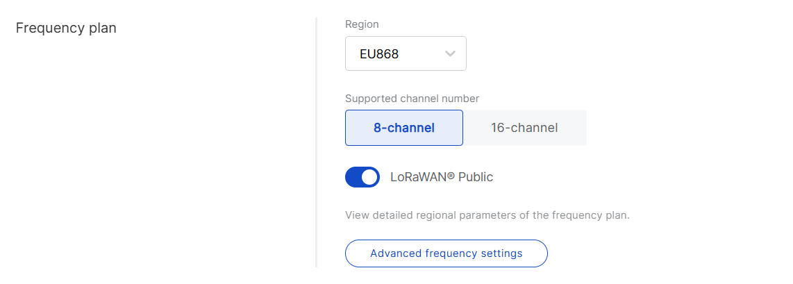 Figure 1: Frequency Plan
-
Region: Select the frequency band that matches your country or region.
-
Supported channel number: Select the channel number supported by your gateway, such as 8-channel or 16-channel.
NOTEThe 16-channel gateways can be added to any location, while 8-channel gateways can only be added to 8-channel locations.
-
LoRaWAN Public: Keep this option enabled for standard LoRaWAN deployments. Disable it only when you need to build a private LoRaWAN network.
-
-
Review the Network Server parameters. For a quick start, you can keep the default values unless your deployment has specific LoRaWAN requirements.
-
Click Save location to complete the Location setup.
After selecting a mode, configure only the required basic parameters to complete the LoRaWAN Network setup. For detailed parameter descriptions, see LoRaWAN Network Configuration.
Add a Gateway to the Location
After the Location is created, add a gateway to it. WisDM supports two methods for adding a new gateway to a Location:
| Method | Description |
|---|---|
| Add a gateway manually | Add one new gateway to WisDM. This method is suitable for first-time setup, testing, or small deployments. |
| Upload gateways via CSV | Add multiple new gateways to WisDM at once. This method is suitable for batch onboarding. |
This section demonstrates the basic process of adding a new gateway and confirming that it appears in the Location. The example below uses a Location configured with Built-in Network Server.
In Built-in Network Server mode, the first gateway added to the Location becomes the Central Gateway. Because each Built-in Network Server Location can have only one Central Gateway, the first gateway must be added manually.
The first gateway must be online before it can be added successfully as the Central Gateway.
If your Location uses Packet Forwarder or Basics™ Station mode, you can add the first new gateway manually or upload gateways via CSV. For detailed onboarding options, see Location Gateway Management.
For this quick start, add a new gateway manually.
-
Go to Locations.
-
Select the Location you created.
-
Open the Gateways tab.
-
Click Add Gateway.
-
In the Add a gateway section, enter the gateway information.
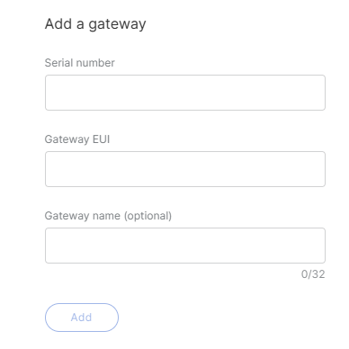 Figure 1: Add a Gateway Manually
- Serial Number: Enter the serial number printed on the gateway label or shown in the gateway Web UI.
- Gateway EUI: Enter the Gateway EUI printed on the gateway label or shown in the gateway Web UI.
- Gateway Name: Optional. Enter a name to identify the gateway in WisDM.
-
Click Add.
-
After the gateway is submitted, the system validates the gateway information to make sure it is compatible with the selected Location.
- Available – The gateway passed validation and can be added to the Location.
- Unavailable – The gateway failed one or more validation checks and cannot be added. Refer to the Status column for the specific reason. For detailed explanations, see Common Status/Errors.
NOTEYou can remove a gateway from the current verification list at any time by clicking the delete icon next to the gateway entry. This action is available in both the Available and Unavailable lists.
-
If the gateway is listed under Available, select it and click Add gateways.
After the gateway is added successfully, it becomes the Central Gateway of this Location.
For other gateway onboarding scenarios, such as adding multiple gateways, assigning existing unassigned gateways, adding extender gateways, or replacing the Central Gateway, see Location Gateway Management.
Confirm the Gateway Is Online
After the gateway is added to the Location, check whether it is online.
To confirm gateway status:
- Go to Locations.
- Select the target Location.
- Open the Gateways tab.
- Check the gateway status.
A successfully connected gateway should appear as Online.
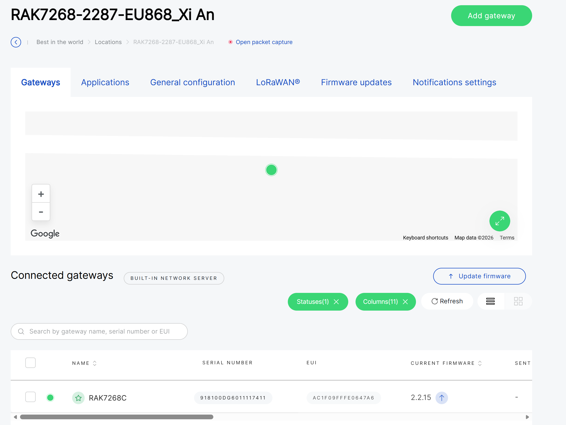 Figure 1: Central gateway
You can also open the gateway details page to view more information, such as firmware version, network status, traffic statistics, and system performance.
For more information, see Gateway Management.
Next Steps
After your first gateway is online, you can continue with the following topics:
| Topic | What You Can Do | Guide |
|---|---|---|
| Gateway Management | View gateway details, monitor status, configure settings, update firmware, and use diagnostics. | Gateway Management |
| Applications and End Devices | Create Applications and register end devices when using Built-in Network Server mode. | Applications |
| Location Gateway Management | Add more gateways, reassign gateways, and manage gateways within a Location. | Location Gateway Management |
| LoRaWAN Network Configuration | Configure work modes, frequency plans, and advanced LoRaWAN parameters. | LoRaWAN Network Configuration |