Quick Start Guide
This section guides you through the steps to bring your first gateway online in WisDM.
Sign in to WisDM
To use WisDM, you must sign in with a RAK ID account.
- Go to the WisDM platform and click Sign in with RAK ID.
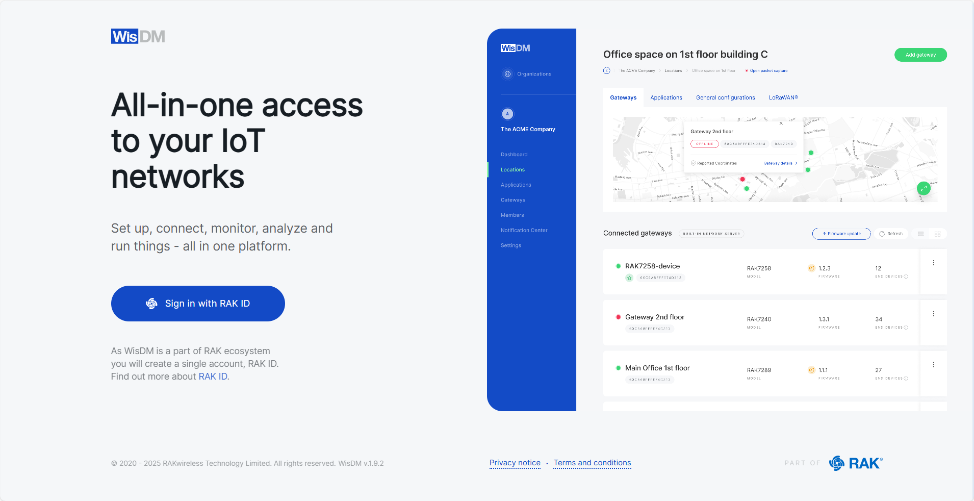 Figure 1: Accessing WisDM
- Choose one of the following options:
-
If you don’t have a RAK ID
- Click Create new and enter your registration details.
 Figure 1: Create RAK ID
- Check your email inbox for the verification code, then enter it.
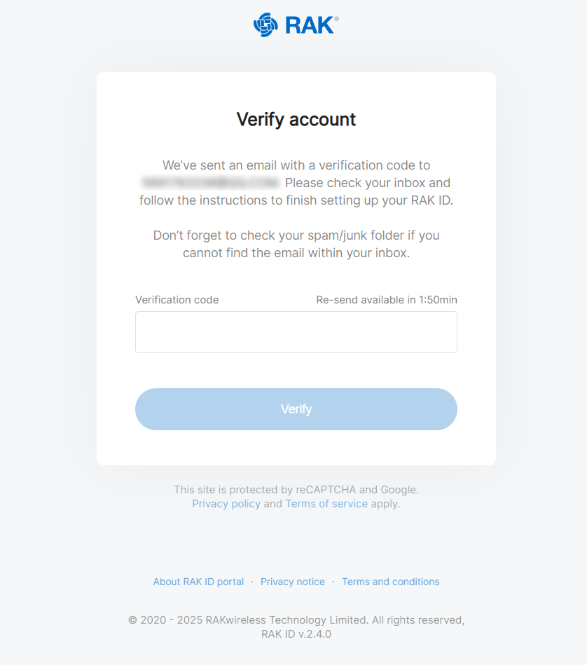 Figure 1: Verify Account
- Read and accept the Terms and Conditions.
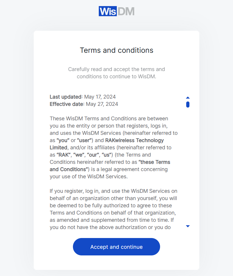 Figure 1: Terms and Conditions
- After completing registration, click New Organization, and you will be redirected to the Organizations page.
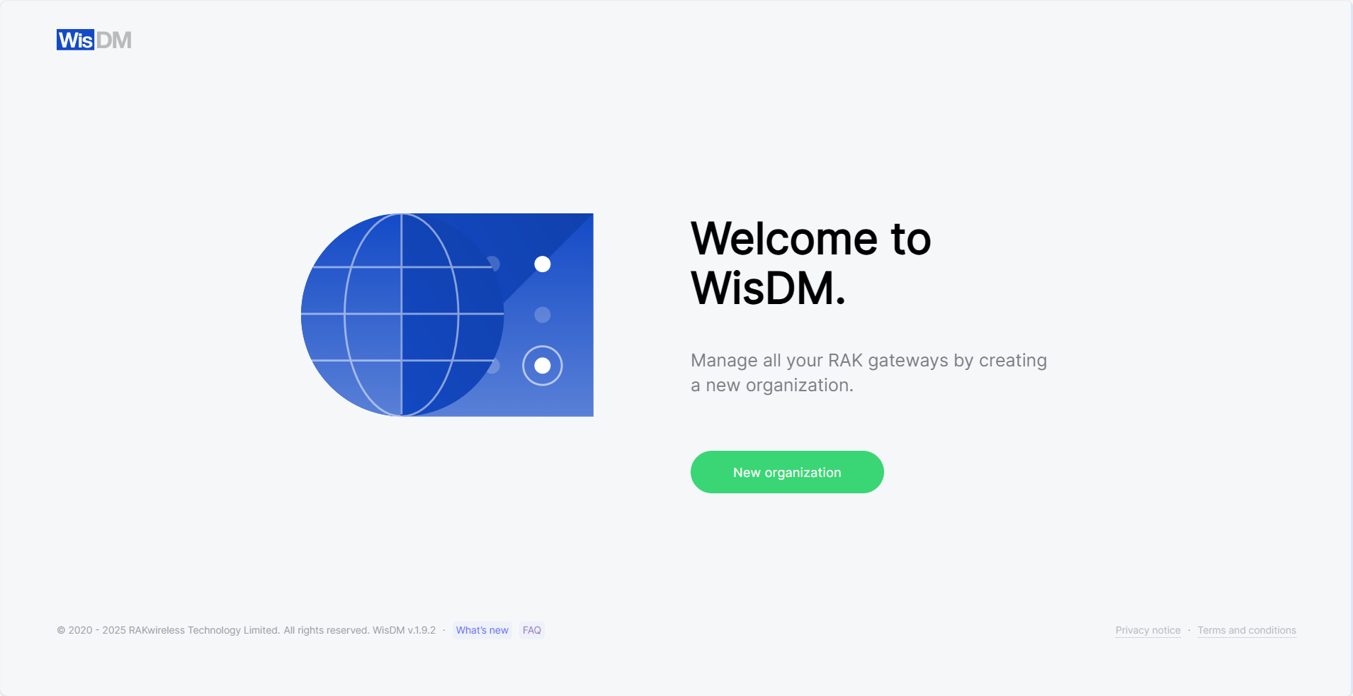 Figure 1: Organizations
 -
If you already have a RAK ID
- Enter your credentials and sign in.
 Figure 1: Login to WisDM
- After successful sign-in, you will be directed to the Organizations page.
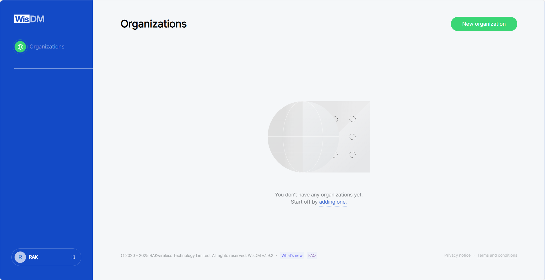 Figure 1: Organizations
Create an Organization
An Organization represents your account in WisDM and serves as the top-level structure that groups all gateways, users, and activities.
- On the Organizations page, click New organization.
- Enter your organization's registration details and click Next.
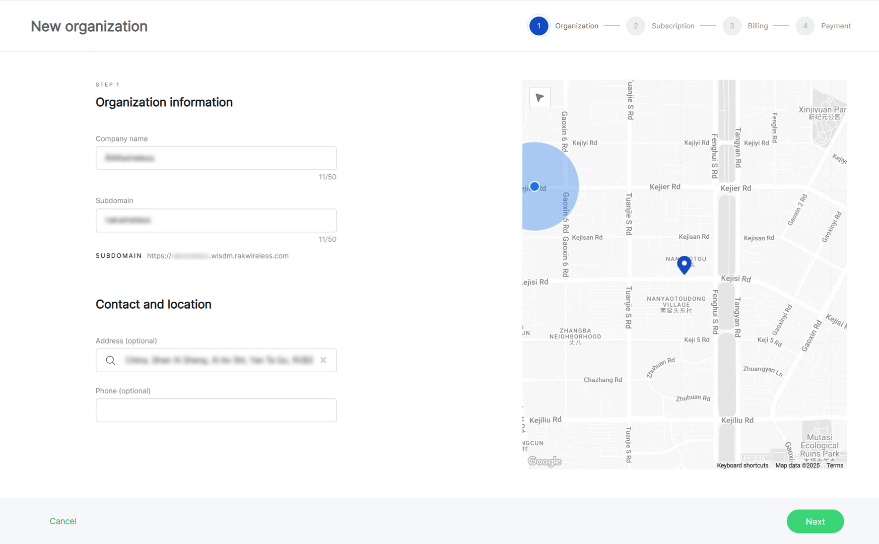 Figure 1: Create an organization
- Company name: Choose a name of your choice, up to 50 characters.
- Subdomain: Automatically generated based on the company name, but customized.
- Address (optional): Add an address by typing in the search box or selecting a location on the map.
- Phone (optional): Optionally, provide a contact phone number.
- Choose a subscription plan.
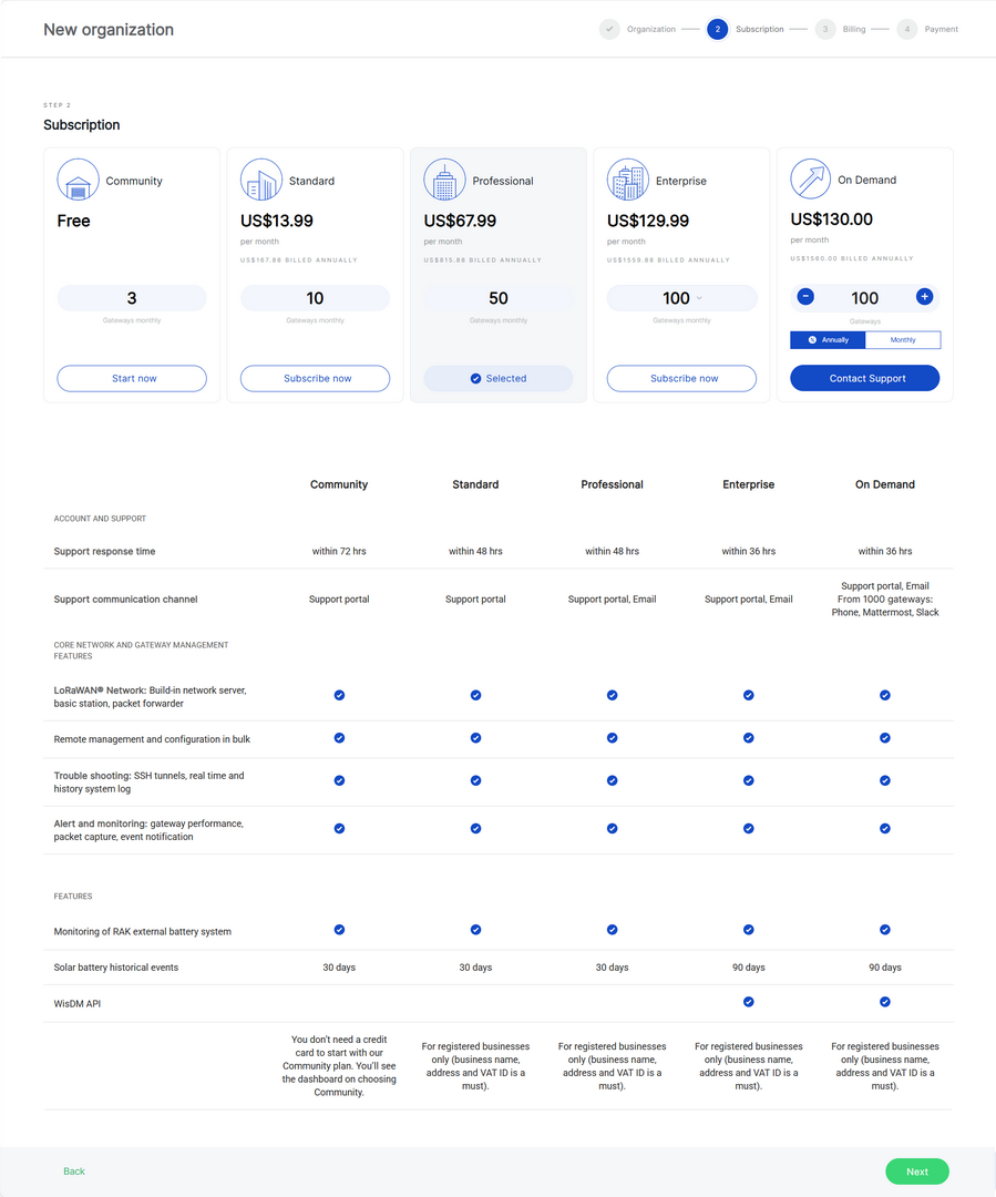 Figure 1: Subscription Plan
- Community (Free): This subscription is free and allows for up to 3 gateways. It is designed for small deployments, DIY projects, proof of concept (POC), and testing purposes.
- Standard: The Standard subscription supports flexible gateway tiers, allowing you to scale from 4 up to 40 gateways, making it suitable for small to medium-sized deployments.
- Professional: The Professional subscription supports multiple gateway tiers, typically ranging from 41 to 90 gateways, making it suitable for medium-sized deployments, system integrators, and solution providers.
- Enterprise: The Enterprise subscription supports large-scale deployments with flexible gateway tiers ranging from 91 up to 1000 gateways. This plan is designed for extensive deployments and enables centralized remote management of many gateways.
- On Demand: A flexible subscription for custom deployments, supporting more than 100 gateways. Users can choose between monthly or annual billing. For setup, please contact support.
If you select Community (Free): Click Start now and then Next. Your organization will be created instantly.
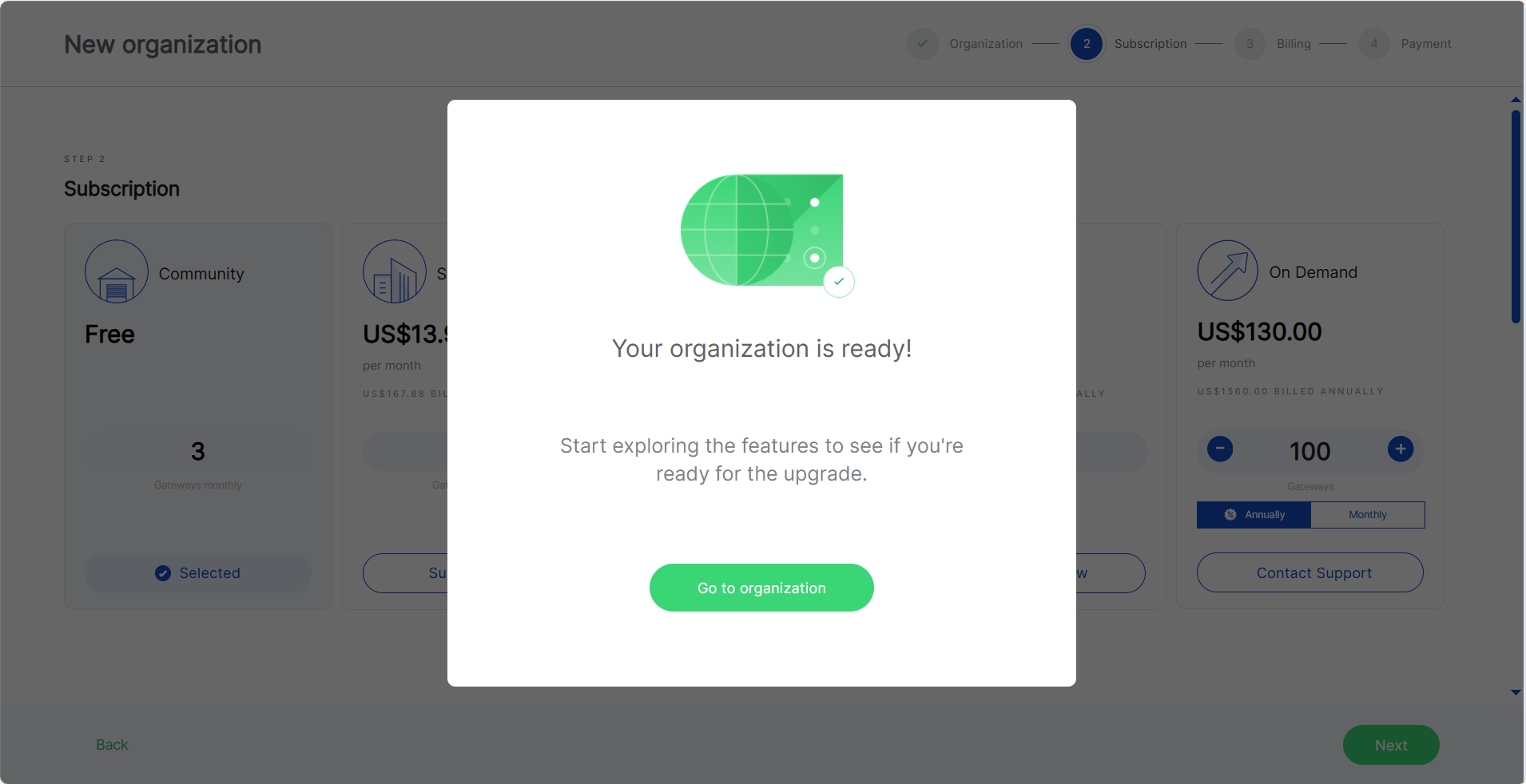 Figure 1: Organization is ready
If you select Standard, Professional, or Enterprise: You will be redirected to the Company Data and Billing Information page. Fill in all required fields, as this information will be used for both the payment process and invoicing. Learn more about WisDM payment security.
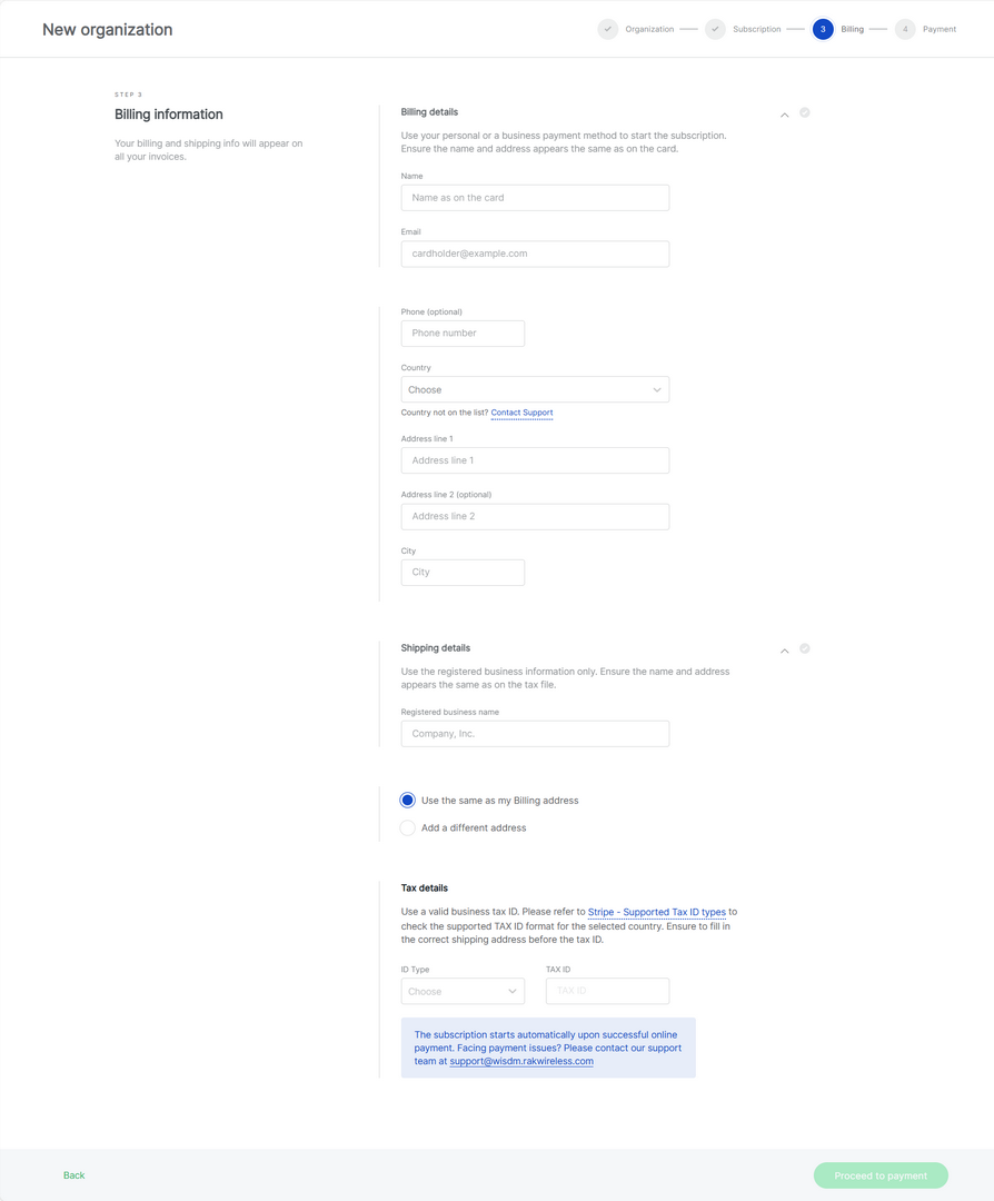 Figure 1: Company data and billing information
If you select On Demand: Choose the number of gateways and billing cycle (monthly or annually). Then click Contact Support for further assistance.
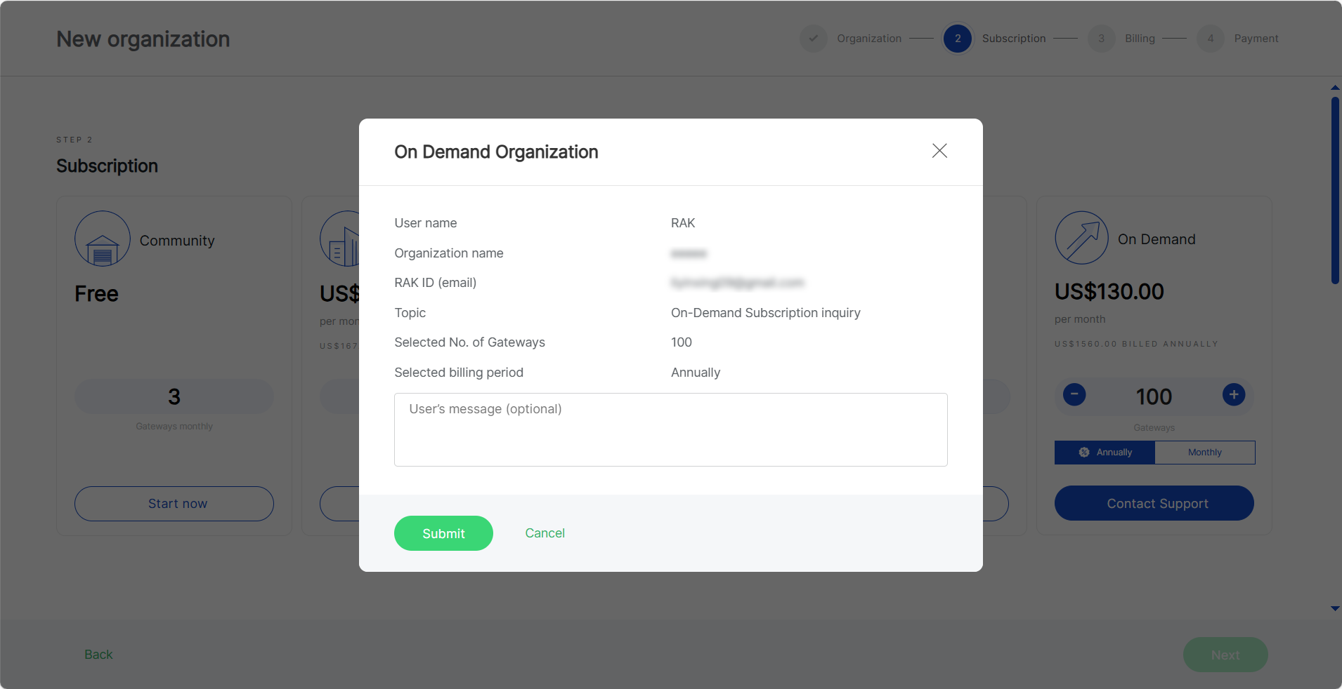 Figure 1: On-Demand Subscription
 More information about the subscription plans and their benefits can be found on the FAQs page.
Add a Location
In WisDM, a Location is a logical entity that defines the connectivity of gateways to the LoRaWAN Network Server (LNS). It organizes the gateways based on their connectivity mode and deployment requirements.
General Information
- On the Locations page, click New location.
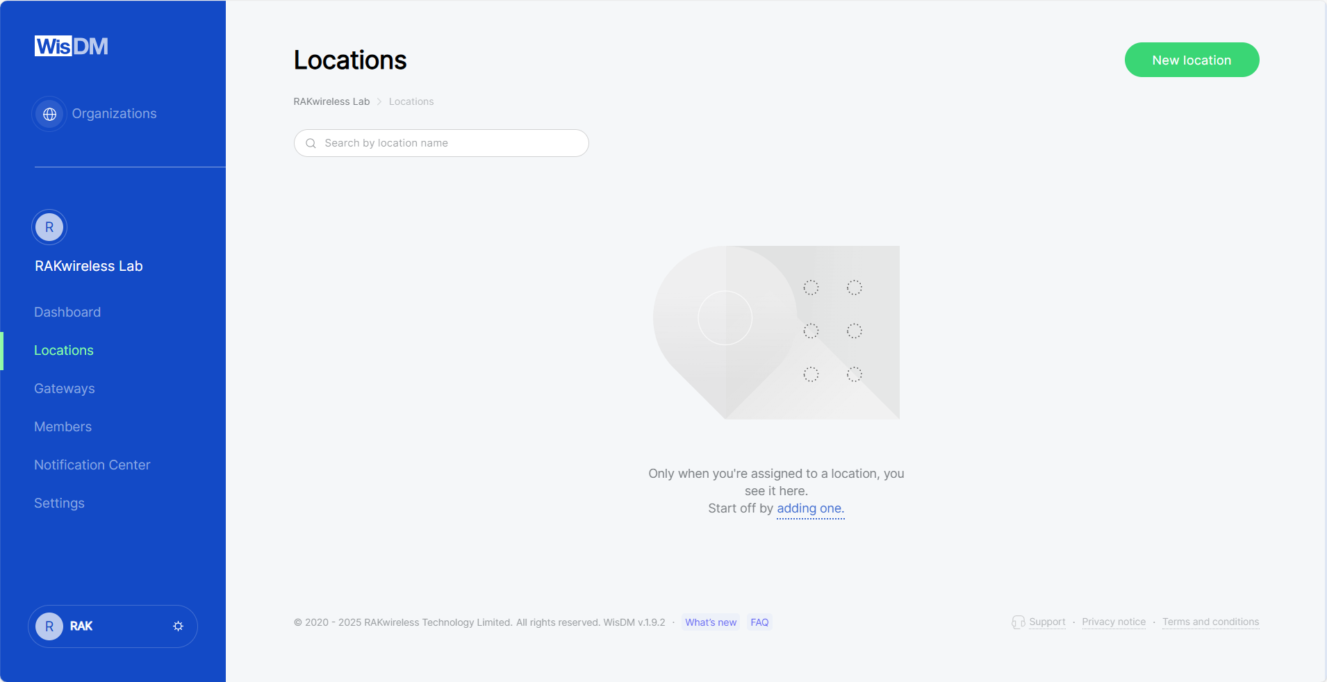 Figure 1: Locations tab
- Enter the location details and click Save location.
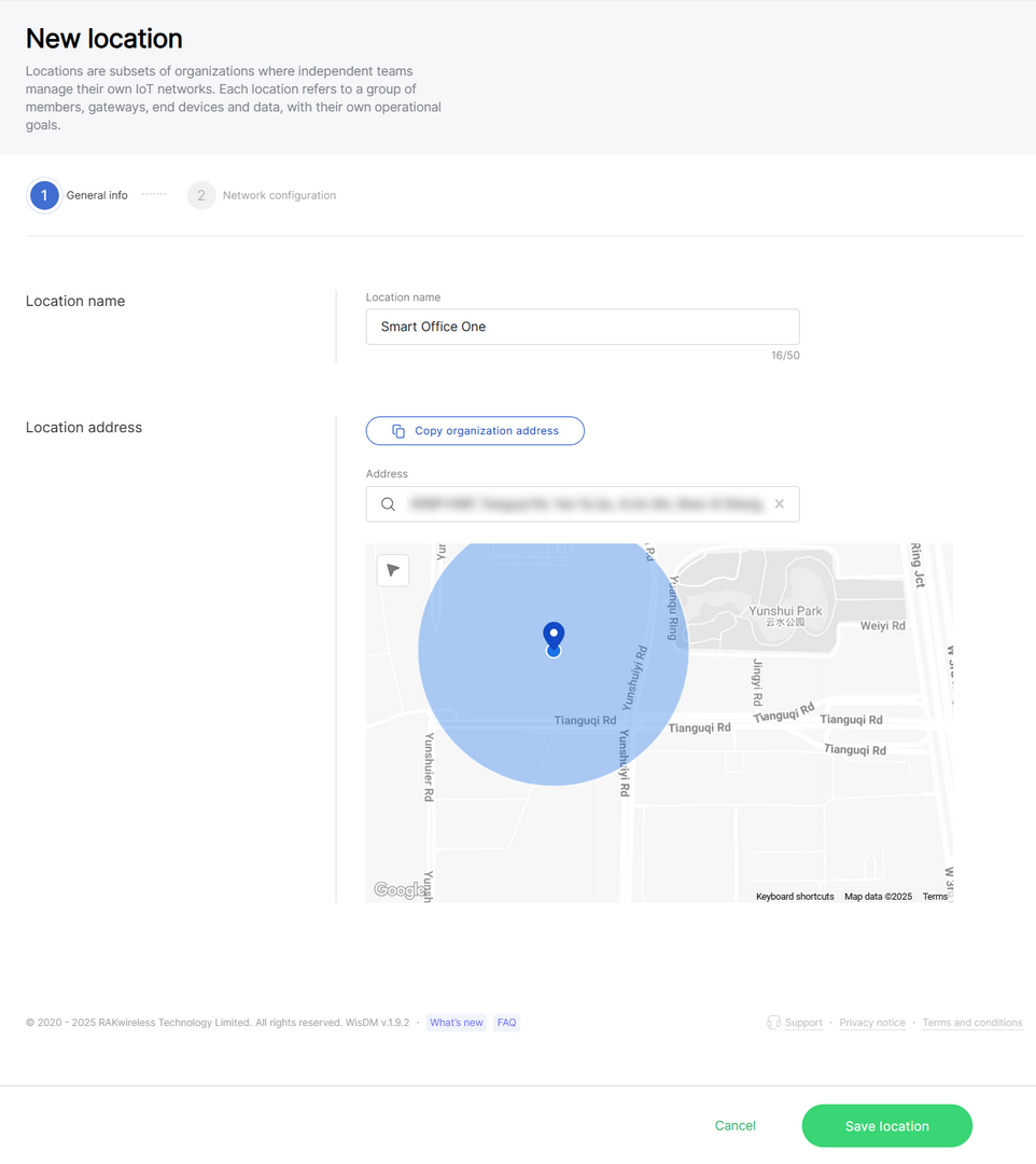 Figure 1: General information
- Location name: Choose a name of your choice, up to 50 characters.
- Location address: Either use the organization's address or provide a new one using the search bar or map.
Network Configuration
WisDM supports building locations with three work modes:
-
Packet Forwarder
A Location set to Packet Forwarder lets gateways forward LoRa traffic to an external LNS using the Semtech UDP Packet Forwarder (GWMP) or the LoRa Gateway MQTT Bridge. The Location defines and pushes shared network settings, such as the frequency plan, to all gateways, ensuring consistency across the fleet.
Gateways operate independently, relaying packets without coordination. This mode is typically used with multiple gateways to cover larger geographical areas or manage high device density. -
Basics Station
A Location set to Basics Station securely connects gateways to an external LNS using the LoRa Basics™ Station protocol (CUPS/LNS). In this mode, the external LNS manages the frequency plan and traffic rules, while WisDM provides centralized configuration of server endpoints and authentication. This simplifies certificate handling and ensures that all gateways in the location adhere to the same connectivity and security standards. -
Built-in Network Server
A Location set to Built-in Network Server designates one gateway as the central server running an embedded LoRaWAN Network Server, while other gateways function as extenders forwarding packets via MQTT. The Location distributes role-specific configurations, synchronizes all gateways, and enables local packet filtering and preprocessing. This creates a self-contained IoT network, ideal for edge deployments or quick pilots that do not rely on an external LNS.
When creating or editing a Location, you can either configure parameters manually or apply an existing template. For details on how to apply or save templates, see Templates.
Packet Forwarder
When the Packet Forwarder mode is selected, gateways under this location will forward data to an external LNS.
 Figure 1: Packet Forwarder work mode
Frequency Plan
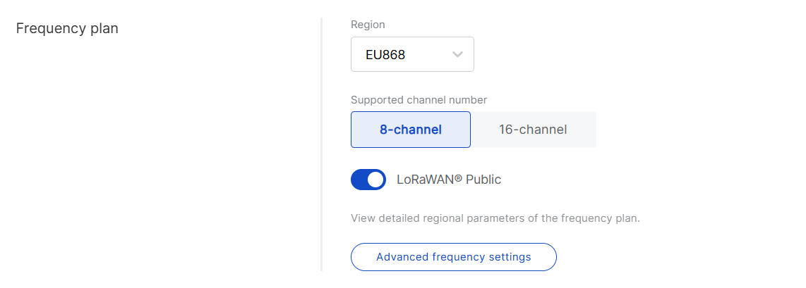 Figure 1: Frequency Plan
- Region: Select the frequency band that corresponds to your country/region. Each region applies LoRaWAN standard limitations and default values for frequencies and channels.
- Supported channel number: Choose between 8-channel or 16-channel based on gateway capability.
NOTE
The 16-channel gateways can be added to any location, while 8-channel gateways can only be added to 8-channel locations.
- LoRaWAN Public: When enabled (by default), the gateway processes data from all end devices operating on the same frequency band. To create a private network, you can disable this option. The gateway will then only process data from end devices with a modified sync word set to private.
- Advanced frequency settings: Fine-tune LoRa sub-bands, Standard LoRa, and FSK channels. Default settings are based on the selected region and supported channel number, as recommended by the LoRaWAN Alliance.
NOTE
- Some regions (e.g., CN470, US915, AU915) use sub-band numbers instead of explicit frequency values, in accordance with local standards.
- Not all frequencies can be changed or removed; mandatory defaults are enforced by the LoRaWAN specification.
- If you provide custom frequencies, WisDM validates them against the gateway hardware to ensure compatibility.
UDP Protocol Parameters
The Semtech UDP Packet Forwarder (GWMP) enables the gateway to communicate with a LNS (LoRa Network Server) using the UDP packet forwarder. Follow these steps to set it up:
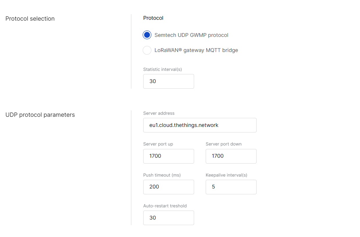 Figure 1: UDP Protocol Parameters
- Protocol: Select Semtech UDP GWMP protocol.
- Statistic interval (s): Specifies the interval (in seconds) at which the gateway sends status reports containing operational and packet processing statistics.
- Server address: Enter the IP address or domain name of your LNS.
- Server port up/down: Input the ports for uplink and downlink communication.
- Push timeout (ms): Set the maximum wait time for an LNS response after sending uplink data.
- Keepalive interval (s): Determine how frequently the gateway sends keepalive messages to verify connectivity.
- Auto-restart threshold: Defines the number of missed keepalive intervals before restarting the Packet Forwarder.
LoRaWAN Gateway MQTT Bridge Parameters
The LoRa gateway MQTT bridge allows the gateway to communicate with an LNS (LoRa Network Server) using the MQTT protocol. Follow these steps to set it up:
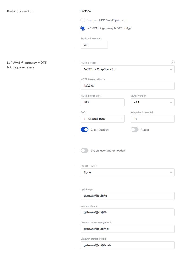 Figure 1: LoRa gateway MQTT bridge parameters
- Protocol: Choose LoRa gateway MQTT bridge.
- Statistic interval (s): Defines the interval (in seconds) at which the gateway sends status reports containing operational and packet processing statistics.
- MQTT protocol:
- MQTT for ChirpStack 2.x
- MQTT for ChirpStack 3.x (JSON)
- MQTT for ChirpStack 3.x (Protobuf)
- MQTT for ChirpStack 4.x (Protobuf)
- MQTT broker address: IP address of the MQTT broker.
- MQTT broker port: Default 1883.
- MQTT version: 3.1 or 3.1.1. See the MQTT GitHub Wiki for details.
- QoS (Quality of Service):
- 0 - At Most Once
- 1 - At Least Once
- 2 - Exactly Once
- Keepalive interval (s): Interval in seconds to keep the connection alive (default:
10). - Clean session: When enabled, the broker does not store session data.
- Retain: If enabled, the last published message is retained.
- Enable user authentication: If enabled, enter Username and Password.
- SSL/TLS mode: Configure secure connection.
- None
- CA signed server certification
- Self-signed server certification
- Self-signed server & client certification
- TLS version: Choose between TLS v1.1 and TLS v1.2.
- Key pass phrase (optional): A password used to unlock an encrypted client private key file.
- Uplink topic/Downlink topic/Downlink acknowledge topic/Gateway statistic topic: Topics are predefined by the selected LNS profile and typically do not require changes.
Packet Filter
Set up a packet filter to optimize bandwidth by forwarding packets only from selected devices (disabled by default).
 Figure 1: Packet Filter
- White List Mode: Disabled by default. Enable it to filter devices based on OUI and Network ID.
- OUI: Filters devices using the first 3 bytes (6 hexadecimal characters) of the DevEUI, which typically identifies the device manufacturer.
- Network ID: A number between 0 and 127 (decimal), derived from the first 7 most significant bits (MSB) of a device’s DevAddr. For example, a DevAddr starting with 0x26 (00100110 in binary) has the first 7 bits as 0010011, which equals decimal 19.
- Auto Filter: Automatically adds trusted devices to the whitelist based on Join request behavior, eliminating the need for manual configuration.
- Join Period (s): Sets the time (in seconds) after which end devices can send join requests again.
- Join Interval (s): Defines the time limit (in seconds) between two consecutive join requests from the same end device.
- Join Count 1: Maximum number of join requests allowed within the join interval.
- Join Count 2: Maximum number of join requests allowed within the join period.
- Discard Period (s): Specifies the duration (in seconds) for which end devices will remain discarded.
After completing the configuration, you can save it as a reusable template for future Locations. See Templates for details.
Basics Station
When the Basics Station mode is selected, gateways in this location use the LoRa Basics™ Station protocol to connect to an external LoRaWAN Network Server (LNS). This mode offers enhanced security and flexibility compared to the legacy packet forwarder.
 Figure 1: Basics Station work mode
Frequency Plan
 Figure 1: Frequency Plan
- Region: Select the frequency band that matches your country/region.
Frequency plan details are typically managed by the network server to which the Basics Station connects. WisDM retains Region/Channel capabilities solely for compatibility checks. It does not push frequency plans to gateways in Basics Station mode.
Basics Station Server Setup
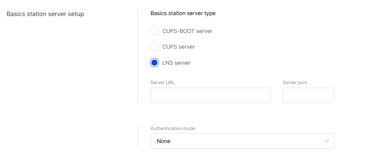 Figure 1: Basics station server setup
- Basics station server type: When configuring Basics Station mode, you can select from the following server types.
- CUPS-BOOT Server: Connects to CUPS only at first boot to request configuration and certificates.
- CUPS Server: Periodically connects to CUPS for configuration updates and firmware upgrade information.
- LNS Server: Forwards LoRaWAN traffic to the Network Server.
- Server URL: Enter the URL of the server that the gateway will connect to.
- Server port: Enter the server's port number.
- Authentication mode: Choose the appropriate authentication mode based on your server's requirements.
- No authentication: The server does not require authentication.
- TLS server authentication: The server requires a trust file for authentication.
- TLS server and client authentication: The server requires a trust file, certificate, and key files for authentication.
- TLS server authentication and client token: The server requires a trust file and a client token.
- Trust (CA Certificate): A file that contains the root certificate authority (CA) used to verify the server's identity.
- Use individual client keys:
- Enabled - Each gateway added to this location can use its own certificate/key/token. An individual certificate/key/token will be added when a gateway is added to the location.
- Disabled - All gateways under this location share the same certificate/key/token information. Provide the certificate/key/token here.
- Client certificate: A digital certificate used to identify the client (gateway) to the server.
- Client key: A private key used in combination with the certificate for mutual TLS authentication. If the client key is pre-installed at the factory, you do not need to upload it manually; WisDM retrieves it automatically when the gateway first comes online.
- Client token: A unique identifier used to authenticate the client without using certificates. If the token is pre-installed on the gateway, WisDM retrieves it automatically the first time the gateway comes online.
Packet Filter
Set up a packet filter to optimize bandwidth by forwarding packets only from selected devices (disabled by default).
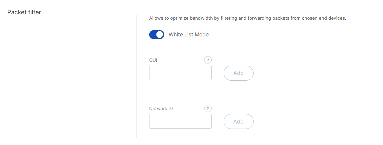 Figure 1: Packet Filter
- White List Mode: Disabled by default. When enabled, it filters devices based on their OUI and Network ID.
- OUI: Filters devices based on the first three bytes (six hexadecimal characters) of the DevEUI, which typically identify the device manufacturer.
- Network ID: A six-character hexadecimal value. Refer to the NetID and DevAddr Prefix Assignments table to determine the network.
After completing the configuration, you can save it as a reusable template for future locations. See Templates for details.
Built-in Network Server
When the Built-in Network Server mode is selected, one central gateway within the location operates as the LoRaWAN Network Server (LNS), while other gateways function as packet forwarders connected to it. This setup allows end devices to be managed directly from WisDM through the central gateway’s built-in LNS, without relying on an external network server.
 Figure 1: Built-in Network Server Work mode
Frequency Plan
Figure 1: Frequency Plan-
Region: Select the frequency band that corresponds to your country or region. Each region adheres to LoRaWAN standard limitations and default values for frequencies and channels.
-
Supported channel number: Choose between 8-channel or 16-channel based on gateway capability.
NOTEThe 16-channel gateways can be added to any location, while 8-channel gateways can only be added to 8-channel locations.
-
LoRaWAN Public: When enabled (by default), the gateway will process data from all end devices operating on the same frequency band. To create a private network, you can disable this option. The gateway will then only process data from end devices with a modified sync word set to private.
-
Advanced frequency settings: Fine-tune LoRa sub-bands, Standard LoRa, and FSK channels. Defaults are based on the selected region and supported channel number, as recommended by the LoRaWAN Alliance.
NOTE- Some regions (e.g., CN470, US915, AU915) use sub-band numbers instead of explicit frequency values, in accordance with local standards.
- Not all frequencies can be changed or removed; mandatory defaults are enforced by the LoRaWAN specification.
- If you provide custom frequencies, WisDM validates them against the gateway hardware to ensure compatibility.
Network Server
Configure general settings for the built-in LoRaWAN Network Server. Default values are pre-filled.
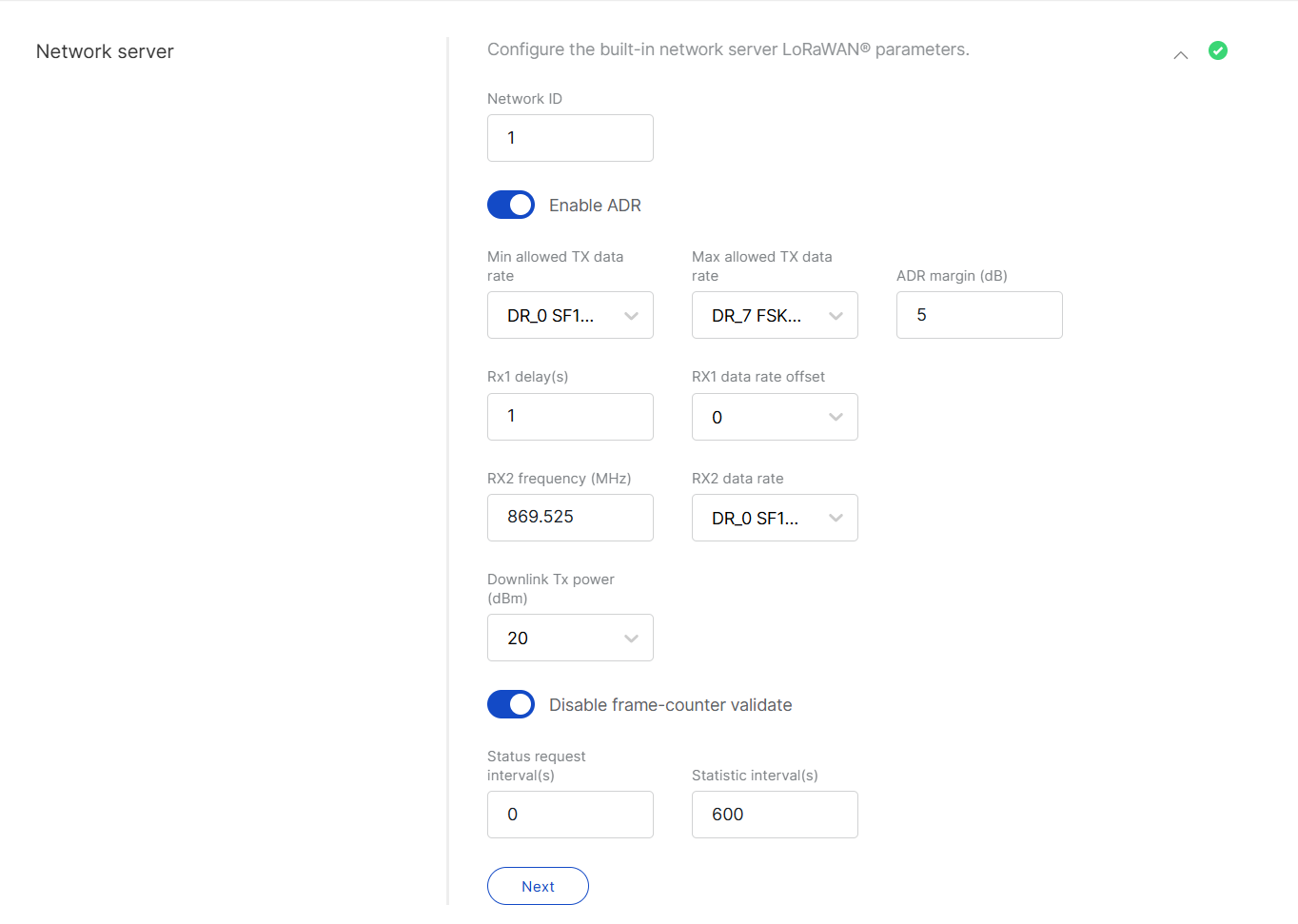 Figure 1: Network Server Parameters
- Network ID: A decimal number used to distinguish between multiple networks when deploying them.
- Enable ADR: Enables or disables Adaptive Data Rate (ADR). When enabled, the server will automatically adjust data rates, airtime, and energy consumption based on current network conditions.
- Min allowed TX data rate: Sets the minimum transmission data rate, which depends on the Region.
- Max allowed TX data rate: Sets the maximum transmission data rate, which depends on the Region.
- ADR margin (dB): Only visible when ADR is enabled. This sets the margin value in dB to prevent overestimating the data rate, which could lead to performance issues such as increased error rates and reduced range.
- Rx1 delay (s): The delay of the first receive window (RX1) in seconds.
- RX1 data rate offset: Determines the data rate for downlink frames sent in the RX1 window. By default, this is set to 0, which is identical to the uplink.
- RX2 frequency (MHz): Sets the frequency of the second receive window (RX2).
- RX2 data rate: Sets the data rate for frames sent in the second receive window.
- Uplink / Downlink dwell time limit: Valid in specific regions only.
- Downlink Tx power (dBm): Useful if you want to use a larger antenna with more gain. Permissible values range from -6 to 20.
- Disable frame-counter validate: This function toggles the frame counter validation on or off.
- Status request interval (s): This indicates how often end devices should be polled for their status log level.
- Statistic interval (s): This shows how often the statistics will be gathered.
Gateway Backend
The Gateway Backend outlines the communication method for gateways within a location using MQTT. When the location is configured in Built-in Network Server mode, one gateway is designated as the central gateway, while the others function as extenders, forwarding their traffic to the central gateway through this backend.
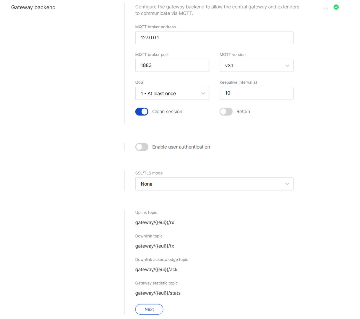 Figure 1: Gateway Backend
- MQTT broker address: Default is 127.0.0.1.
NOTE
- If only one gateway is used, keep the default MQTT broker address
127.0.0.1. - If extender gateways will be added, set the MQTT broker address to the central gateway’s real static IP (as configured in the Network/Internet settings). All extender gateways will use this IP to connect to the MQTT Broker and the running built-in Network Server.
- If only one gateway is used, keep the default MQTT broker address
- MQTT broker port: The port used by the broker (default:
1883). - MQTT version: 3.1 or 3.1.1. See the MQTT GitHub Wiki for details.
- QoS (Quality of Service):
- 0 - At Most Once
- 1 - At Least Once
- 2 - Exactly Once
- Keepalive interval (s): Interval in seconds to keep the connection alive (default:
10). - Clean session: When enabled, the broker does not store subscription or undelivered messages.
- Retain: When enabled, the last message will be retained.
- Enable user authentication: If enabled, enter Username and Password.
- SSL/TLS Mode: Configure secure connection
- None
- CA signed server certification
- Self-signed server certification
- Self-signed server and client certification
- TLS Version: Choose between TLS v1.1 and TLS v1.2.
- Key pass phrase (optional): A password used to unlock an encrypted client private key file.
- Uplink topic/Downlink topic/Downlink acknowledge topic/Gateway statistic topic: Predefined MQTT topics for uplink, downlink, and status updates.
Integrate with External Platforms
The Integration Interface forwards uplink data received by the built-in network server to external MQTT-compatible platforms or cloud services (e.g., AWS IoT Core) for visualization, processing, and integration.
 Figure 1: Integration Interface Parameters
- Enable integration interface: Enables the integration interface.
- Generic MQTT: In this configuration, the location functions as an MQTT client that publishes messages to an external MQTT broker.
- MQTT broker address: The IP address of the MQTT broker.
- MQTT broker port: The port used by the broker.
- MQTT version: 3.1 or 3.1.1. See the MQTT GitHub Wiki for details.
- QoS: Quality of Service level:
- 0 - At Most Once
- 1 - At Least Once
- 2 - Exactly Once
- Keepalive interval (s): The interval in seconds to keep the connection alive (default:
10). - Clean session: When enabled, the broker does not store session data.
- Retain: If enabled, the last published message is retained.
- Client ID: ID used to associate with the topic (auto-generated if left empty).
- Enable user authentication: If enabled, enter Username and Password.
- SSL/TLS mode: Configure secure connection
- None
- CA signed server certification
- Self-signed server certification
- Self-signed server and client certification
- TLS version: Choose between TLS v1.1 and TLS v1.2.
- Key pass phrase (optional): A password used to unlock an encrypted client private key file.
- Join topic / Uplink topic / Downlink topic / Downlink acknowledge topic / Status topic: Predefined MQTT topics used to publish messages.
- AWS IoT Core:
- AWS IoT Core endpoint URL: The AWS endpoint address.
- AWS IoT Core endpoint port: The port used by the AWS server.
- Root CA: CA certificate provided by AWS IoT Core.
- Certificate: Gateway certificate generated by AWS IoT Core.
- Key: Private key for the gateway, generated by AWS IoT Core.
After completing the configuration, you can save it as a reusable template for future Locations. See Templates for details.
Templates
WisDM allows you to save any Location configuration as a reusable template. Templates enable you to quickly apply the same LoRaWAN settings to new or existing Locations.
- Save as template: After configuring a Location, click Save as template to store the settings for reuse.
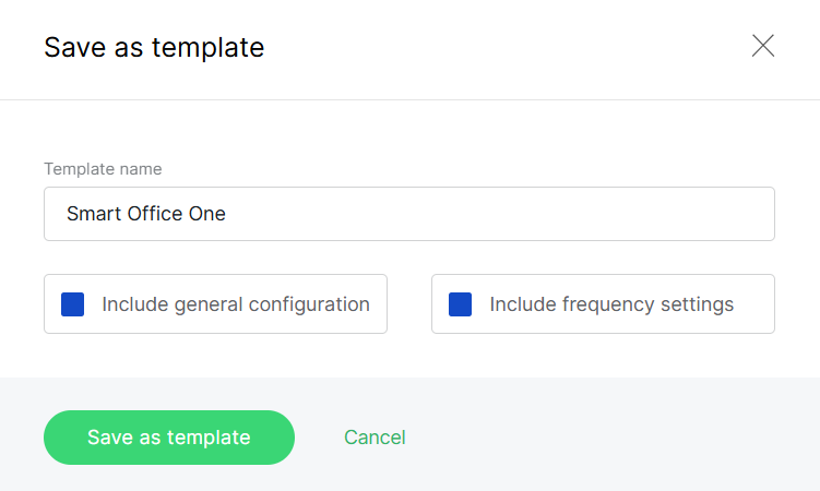 Figure 1: Save as template
- Apply an existing template: When creating or editing a Location, click Choose in the Existing template section and select a saved template.
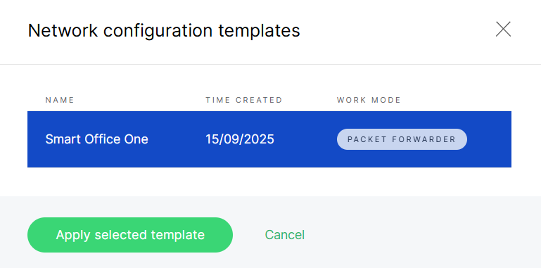 Figure 1: Select a template
Templates are available for all Location work modes (Packet Forwarder, Basics Station, and Built-in Network Server).
Add a Gateway to a Location
Based on your Location’s work mode, follow the corresponding guide to add a gateway and bring your first device online quickly.
Prerequisites
Before adding a gateway to a Location, ensure you have the following:
- Serial Number and Gateway EUI (found on the device sticker or in the Web UI > Dashboard > Overview).
- WisDM integration is enabled on the gateway.
- The gateway and the Location must have the same region configuration.
Add Gateways in Packet Forwarder Mode
This section guides you through onboarding gateways to a Location, either by assigning unassigned gateways, uploading them via CSV, or adding them manually.
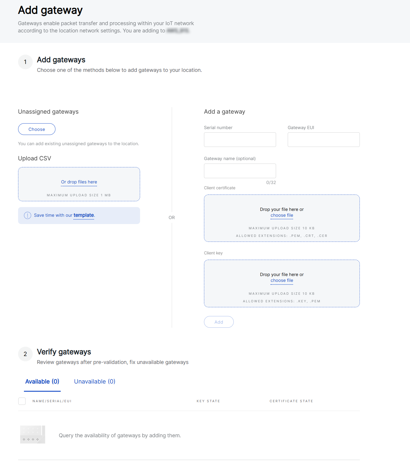 Figure 1: Adding a gateway in PF mode
Add from Unassigned Gateways
- Click Choose under Unassigned gateways to add a gateway that was previously removed from a Location.
- From the Unassigned gateways list, select the gateway and click Apply selected.
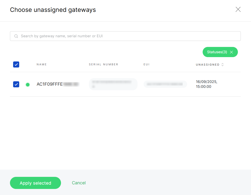 Figure 1: Select gatewaysNOTE
- Search bar: You can search unassigned gateways by entering their gateway name, serial number, or EUI in the search field. This helps quickly locate a specific gateway in large lists.
- Status filter: Click the Statuses button to filter gateways by their connection status:
- All - Displays all gateways.
- Online - Show only gateways that are currently connected.
- Offline - Display gateways that are disconnected.
- Pre-provisioning - Show gateways that are prepared for onboarding but not yet active.
- After the gateway is selected, the system performs a pre-validation process (verifying frequency compatibility, identifier validity, and assignment status). Gateway is categorized into:
- Available - Gateways that successfully pass all validation checks and meet the requirements of the selected Location.
- Unavailable - Gateways that fail one or more validation checks and cannot be added. Refer to the Status column for the specific reason.
- Select the gateway under Available, then click Add gateways.
Upload Multiple Gateways via CSV
- Click template to download the provided CSV template.
- Fill in the required gateway details in the CSV file:
- Serial Number
- Gateway EUI
- Gateway Name
NOTEMaximum upload size: 1 MB.
- Drag and drop the file into the upload area, or click Or drop files here to upload.
- After the CSV file is uploaded, the system performs a pre-validation process (verifying frequency compatibility, identifier validity, and assignment status). Gateways are categorized into:
- Available - Gateways that successfully pass all validation checks and meet the requirements of the selected Location.
- Unavailable - Gateways that fail one or more validation checks and cannot be added. Refer to the Status column for the specific reason.
- Select the gateways under Available, then click Add gateways.
Add a Gateway Manually
- Enter the Serial Number.
- Enter the Gateway EUI.
- Optionally, enter a Gateway Name (up to 32 characters).
- Click Add.
- After the gateway is added, the system performs a pre-validation process (verifying frequency compatibility, identifier validity, and assignment status). The gateway is categorized into:
- Available - Gateways that successfully pass all validation checks and meet the requirements of the selected Location.
- Unavailable - Gateways that fail one or more validation checks and cannot be added. Refer to the Status column for the specific reason.
- Select the gateway under Available, then click Add gateways.
Add Gateways in Basics Station Mode
This section guides you through onboarding gateways to a Location in Basics™ Station (BS) mode, either by assigning unassigned gateways, uploading them via CSV, or adding them manually.
Figure 1: Adding a gateway in BS modeAdd from Unassigned Gateways
-
Click Choose under Unassigned gateways to add a gateway that was previously removed from a Location.
-
From the Unassigned gateways list, select the gateway you want to add and click Apply selected.
Figure 1: Select gatewaysNOTE- Search bar: You can search unassigned gateways by entering their gateway name, serial number, or EUI in the search field. This helps quickly locate a specific gateway in large lists.
- Status filter: Click the Statuses button to filter gateways by their connection status:
- All - Displays all gateways.
- Online - Show only gateways that are currently connected.
- Offline - Display gateways that are disconnected.
- Pre-provisioning - Show gateways that are prepared for onboarding but not yet active.
-
After the gateway is selected, the system performs a pre-validation process (verifying frequency compatibility, identifier validity, and assignment status). Gateway is categorized into:
- Available - Gateways that successfully pass all validation checks and meet the requirements of the selected Location.
- Unavailable - Gateways that fail one or more validation checks and cannot be added. Refer to the Status column for the specific reason.
-
For gateways listed under Available, if authentication credentials are required, the system displays the Key State and Certificate State.
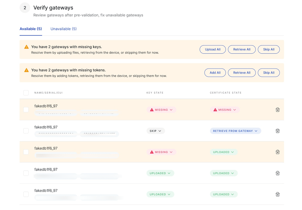 Figure 1: Gateway key and certificate status after CSV upload
If multiple gateways have missing credentials, you can manage them in bulk.
Alternatively, for individual gateways, click the dropdown under Key State or Certificate State and select:
- Upload file - Upload the required authentication file.
- Retrieve from gateway - Retrieve credentials from the gateway after assignment.
- Skip - Temporarily skip credential configuration.
-
Once all required credentials are configured, click Add gateways to complete the onboarding.
Upload Multiple Gateways via CSV
-
Click template to download the provided CSV template.
-
Fill in the required gateway details in the CSV file:
- Serial Number
- Gateway EUI
- Gateway Name
-
Drag and drop the file into the upload area, or click Or drop files here to upload.
-
After the CSV file is uploaded, the system performs a pre-validation process (verifying frequency compatibility, identifier validity, and assignment status). Gateways are categorized into:
- Available - Gateways that successfully pass all validation checks and meet the requirements of the selected Location.
- Unavailable - Gateways that fail one or more validation checks and cannot be added. Refer to the Status column for the specific reason.
-
For gateways listed under Available, if authentication credentials are required, the system displays the Key State and Certificate State.
Figure 1: Gateway key and certificate status after CSV uploadIf multiple gateways have missing credentials, you can manage them in bulk.
Alternatively, for individual gateways, click the dropdown under Key State or Certificate State and select:
- Upload file - Upload the required authentication file.
- Retrieve from gateway - Retrieve credentials from the gateway after assignment.
- Skip - Temporarily skip credential configuration.
-
Once all required credentials are configured, click Add gateways to complete the onboarding.
Add a Gateway Manually
- Enter the Serial Number.
- Enter the Gateway EUI.
- Optionally, enter a Gateway Name (up to 32 characters).
- Upload the required authentication files if Use individual client keys is enabled during Location creation.
- Click Add.
- After the gateway is added, the system performs a pre-validation process (verifying frequency compatibility, identifier validity, and assignment status). The gateway is categorized into:
- Available - Gateways that successfully pass all validation checks and meet the requirements of the selected Location.
- Unavailable - Gateways that fail one or more validation checks and cannot be added. Refer to the Status column for the specific reason.
- Select the gateway under Available, then click Add gateways.
Add Gateways in Built-in Network Server Mode
This section guides you through the process of onboarding gateways to a Location in Built-in Network Server. The workflow varies slightly depending on whether you are adding the first gateway or adding additional gateways, the workflow is slightly different.
Gateway Roles in Built-in Network Server
- Central Gateway
- The first gateway added to a Location.
- Each Location can only have one Central Gateway at any time.
- Extender Gateway
- Additional gateways that extend the coverage of the Central Gateway.
- Multiple Extenders gateways can be added under the same Location.
Add the First Gateway (Central)
When no gateway exists in the Location, the first gateway you add will always be the Central Gateway.
The Central Gateway must be online to be successfully added.
- Go to Locations and click Add gateway.
 Figure 1: Add the first gateway
- Choose from Unassigned gateways or enter the following manually:
- Gateway Serial Number
- Gateway EUI
- Gateway Name (optional, up to 32 characters)
- Click Add gateway to complete the process.
- The option Add as central is enabled by default and cannot be modified.
- When adding the first gateway, you can only add one gateway at a time.
Add Extender Gateways
Once a Central Gateway is established, all subsequently added gateways are treated as Extender Gateways by default. However, Extender Gateways can only be added when the Central Gateway is online, ensuring proper synchronization and network functionality.
- Go to Locations and click Add gateway.
Figure 1: Add Extender Gateways- You can add Extenders Gateways in the same way as in Packet Forwarder mode (choose from unassigned gateways, upload via CSV, or add manually). For detailed instructions, refer to the Add gateway - Packet Forwarder mode section.
If you need to replace the current Central Gateway, enable Add as central in the same form. This will reconfigure the Location automatically and unassign the previous Central. Since each Location can only have one Central, the interface will only show the manual add form in this case.
Next Step
Adding gateways completes the basic setup for Built-in Network Server mode. If you also need to manage Applications or End Devices, see Applications (Built-in Network Server).