WisBlock Agriculture Kit Quick Start Guide
Prerequisite
What Do You Need?
The WisBlock Agriculture Kit includes the RAK19007 and RAK19001 WisBlock Base boards, along with two RAK4631 WisBlock Core modules, and a set of sensor modules. Before proceeding with the steps for using the WisBlock Agriculture Kit, ensure you have the following items prepared:
- RAK4631 WisBlock Core
- RAK19007 WisBlock Base Board
- RAK19001 WisBlock Base Board
- RAK12019 UV Sensor
- RAK12010 Ambient Light Sensor
- RAK1906 Environment Sensor
- RAK12023 + RAK12035 Soil Moisture Sensor
- RAK12005 + RAK12030 Rain Sensor
- USB-C Cable
- RAK19005 Sensor Extension Cable (optional)
- RAK19008 IO Extension Cable (optional)
- Li-Ion/LiPo battery (optional)
- Solar charger (optional)
Software
Arduino
- Download and install ArduinoIDE.
- To add the RAKwireless Core boards on your Arduino Boards Manager, install the RAKwireless Arduino BSP.
Product Configuration��
Hardware Setup and Sample Applications
The WisBlock Agriculture Kit includes soil moisture, UV light, barometric pressure, ambient light, and environmental sensor modules. These sensors are compatible with both the RAK19007 and RAK19001 WisBlock Base boards, providing you with options to choose from.
Primarily, this kit will assist you in learning how to measure soil conditions and monitor the environment. You can select the appropriate device for your specific application.
- Soil Monitoring Device - RAK4631 + RAK12023/RAK12035 + RAK12005/RAK12030
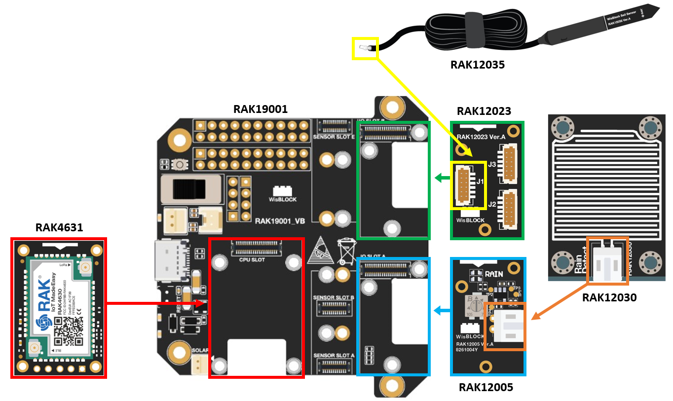 Figure 1: RAK4631 + RAK12023/RAK12035 + RAK12005/RAK12030
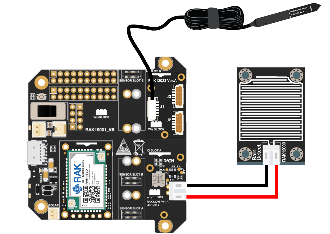 Figure 1: RAK4631 + RAK12023/RAK12035 + RAK12005/RAK12030
- Weather Monitoring Device - RAK4631 + RAK12019 + RAK12010 + RAK1906
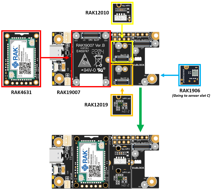 Figure 1: RAK4631 + RAK12019 + RAK12010 + RAK1906
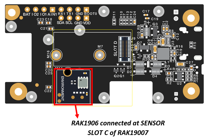 Figure 1: RAK1906 connected at Sensor Slot C of RAK19007
Assembly and Functionality Testing of WisBlock Agriculture Modules
This kit makes use of the different WisBlock Agriculture modules. Refer to the following list for more information on their assemblies and functionalities:
- RAK12019 UV Sensor
- RAK12010 Ambient Light Sensor
- RAK1906 Environment Sensor
- RAK12023 Soil Moisture Sensor Connector
- RAK12035 Soil Moisture Sensor
- RAK12005 Rain Sensor
Software Configuration and Examples
LoRaWAN Applications for WisBlock Agriculture Kit Using TTN and Akenza
Soil Condition Monitoring LoRaWAN Application
The Soil Condition Monitoring LoRaWAN Application is utilized for monitoring soil conditions using multiple sensor modules. It employs the RAK12023/RAK12035 combination for measuring soil conditions and the RAK12005/RAK12030 combination for rain detection and monitoring.
Figure 1: Soil Monitoring DeviceSoil Condition Monitoring - TTN and Device Registration Section
- If you already have an existing TTN account, you may proceed to the next steps. If you do not have an account yet, go to the The Things Network Configuration section and create one.
- Once you've created your TTN account, you can proceed with device registration. Go to the OTAA Device Registration section.
LoRaWAN Code for Soil Condition Monitoring
- If you already have the Arduino IDE installed on your laptop or PC and have added the RAK4631 board to it, you can proceed to the next step. If you haven't installed the Arduino IDE yet, go to the RAK4631 Installation section and follow the provided steps.
- After the installation, proceed to program the Soil Condition Monitoring device. Simply copy the Soil Condition Monitoring LoRaWAN Application code provided below and paste it into the Arduino IDE.
The example code uses SX126x-Arduino library which needs to be added to successfully compile the LoRaWAN code.
Click to view the example
#include <Arduino.h>
#include <LoRaWan-RAK4630.h>           // http://librarymanager/All#SX126x
#include <Wire.h>
#include "RAK12035_SoilMoisture.h"     // http://librarymanager/All#RAK12035_SoilMoisture
#define SENSOR_PIN  WB_IO6             // Attach Water sensor to Arduino Digital Pin WB_IO6

RAK12035 sensor;

/** Set these two values after the sensor calibration was done **/
uint16_t zero_val = 73;
uint16_t hundred_val = 250;

uint16_t capacitance = 0;
uint8_t moisture = 0;
uint16_t temperature = 0;
int rain_sensor;

#ifdef RAK4630
#define BOARD "RAK4631 "
#define RAK4631_BOARD true
#else
#define RAK4631_BOARD false
#endif

bool doOTAA = true;                                               // OTAA is used by default.
#define SCHED_MAX_EVENT_DATA_SIZE APP_TIMER_SCHED_EVENT_DATA_SIZE /**< Maximum size of scheduler events. */
#define SCHED_QUEUE_SIZE 60                                       /**< Maximum number of events in the scheduler queue. */
#define LORAWAN_DATERATE DR_0                                     /*LoRaMac datarates definition, from DR_0 to DR_5*/
#define LORAWAN_TX_POWER TX_POWER_5                               /*LoRaMac tx power definition, from TX_POWER_0 to TX_POWER_15*/
#define JOINREQ_NBTRIALS 3                                        /**< Number of trials for the join request. */
DeviceClass_t g_CurrentClass = CLASS_A;                           /* class definition*/
LoRaMacRegion_t g_CurrentRegion = LORAMAC_REGION_US915;           /* Region:EU868*/
lmh_confirm g_CurrentConfirm = LMH_CONFIRMED_MSG;                 /* confirm/unconfirm packet definition*/
uint8_t gAppPort = LORAWAN_APP_PORT;                              /* data port*/

/**@brief Structure containing LoRaWan parameters, needed for lmh_init()
*/
static lmh_param_t g_lora_param_init = { LORAWAN_ADR_ON, LORAWAN_DATERATE, LORAWAN_PUBLIC_NETWORK, JOINREQ_NBTRIALS, LORAWAN_TX_POWER, LORAWAN_DUTYCYCLE_OFF };

// Forward declaration
static void lorawan_has_joined_handler(void);
static void lorawan_join_failed_handler(void);
static void lorawan_rx_handler(lmh_app_data_t *app_data);
static void lorawan_confirm_class_handler(DeviceClass_t Class);
static void send_lora_frame(void);

/**@brief Structure containing LoRaWan callback functions, needed for lmh_init()
*/
static lmh_callback_t g_lora_callbacks = { BoardGetBatteryLevel, BoardGetUniqueId, BoardGetRandomSeed,
                                           lorawan_rx_handler, lorawan_has_joined_handler, lorawan_confirm_class_handler, lorawan_join_failed_handler };
//OTAA keys !!!! KEYS ARE MSB !!!!
uint8_t nodeDeviceEUI[8] = { 0xAC, 0x00, 0x00, 0x00, 0x00, 0x00, 0x00, 0x00 };
uint8_t nodeAppEUI[8] = { 0x00, 0x00, 0x00, 0x00, 0x00, 0x00, 0x00, 0x00 };
uint8_t nodeAppKey[16] = { 0x96, 0xBD, 0xC5, 0x98, 0x17, 0x69, 0x8D, 0xFA, 0x1F, 0x64, 0xFE, 0x1C, 0xF9, 0x26, 0x7F, 0x8D };

// ABP keys
uint32_t nodeDevAddr = 0x260116F8;
uint8_t nodeNwsKey[16] = { 0x7E, 0xAC, 0xE2, 0x55, 0xB8, 0xA5, 0xE2, 0x69, 0x91, 0x51, 0x96, 0x06, 0x47, 0x56, 0x9D, 0x23 };
uint8_t nodeAppsKey[16] = { 0xFB, 0xAC, 0xB6, 0x47, 0xF3, 0x58, 0x45, 0xC7, 0x50, 0x7D, 0xBF, 0x16, 0x8B, 0xA8, 0xC1, 0x7C };

// Private definition
#define LORAWAN_APP_DATA_BUFF_SIZE 64                                            /**< buffer size of the data to be transmitted. */
static uint8_t m_lora_app_data_buffer[LORAWAN_APP_DATA_BUFF_SIZE];               //< Lora user application data buffer.
static lmh_app_data_t m_lora_app_data = { m_lora_app_data_buffer, 0, 0, 0, 0 };  //< Lora user application data structure.

static uint32_t count = 0;
static uint32_t count_fail = 0;

void setup() {

  pinMode(SENSOR_PIN, INPUT);     // The Water Sensor is an Input
  pinMode(LED_GREEN, OUTPUT);     // The LED is an Output

  // Initialize Serial for debug output
	pinMode(LED_BLUE, OUTPUT);
	digitalWrite(LED_BLUE, HIGH);

  // Initialize LoRa chip.
  lora_rak4630_init();

  // Initialize Serial for debug output
  time_t timeout = millis();
  Serial.begin(115200);
  while (!Serial) {
    if ((millis() - timeout) < 5000) {
      delay(100);
    } else {
      break;
    }
  }

  Serial.println("=====================================");
  Serial.println("Welcome to RAK4630 LoRaWan!!!");
  if (doOTAA) {
    Serial.println("Type: OTAA");
  } else {
    Serial.println("Type: ABP");
  }

  switch (g_CurrentRegion) {
    case LORAMAC_REGION_AS923:
      Serial.println("Region: AS923");
      break;
    case LORAMAC_REGION_AU915:
      Serial.println("Region: AU915");
      break;
    case LORAMAC_REGION_CN470:
      Serial.println("Region: CN470");
      break;
    case LORAMAC_REGION_EU433:
      Serial.println("Region: EU433");
      break;
    case LORAMAC_REGION_IN865:
      Serial.println("Region: IN865");
      break;
    case LORAMAC_REGION_EU868:
      Serial.println("Region: EU868");
      break;
    case LORAMAC_REGION_KR920:
      Serial.println("Region: KR920");
      break;
    case LORAMAC_REGION_US915:
      Serial.println("Region: US915");
      break;
  }
  Serial.println("=====================================");

  // Setup the EUIs and Keys
  if (doOTAA) {
    lmh_setDevEui(nodeDeviceEUI);
    lmh_setAppEui(nodeAppEUI);
    lmh_setAppKey(nodeAppKey);
  } else {
    lmh_setNwkSKey(nodeNwsKey);
    lmh_setAppSKey(nodeAppsKey);
    lmh_setDevAddr(nodeDevAddr);
  }

  uint32_t err_code;
  // Initialize LoRaWan
  err_code = lmh_init(&g_lora_callbacks, g_lora_param_init, doOTAA, g_CurrentClass, g_CurrentRegion);
  if (err_code != 0) {
    Serial.printf("lmh_init failed - %d\n", err_code);
    return;
  }

  // Start Join procedure
  lmh_join();

  Serial.println("================================");
  Serial.println("RAK12035 + RAK12005 LoRaWAN Code");
  Serial.println("================================");

	Wire.begin();

  // Initialize sensor
	sensor.begin();

	// Get sensor firmware version
	uint8_t data = 0;
	sensor.get_sensor_version(&data);
	Serial.print("Sensor Firmware version: ");
	Serial.println(data, HEX);
	Serial.println();

	// Set the calibration values
	// Reading the saved calibration values from the sensor.
	sensor.get_dry_cal(&zero_val);
	sensor.get_wet_cal(&hundred_val);
	Serial.printf("Dry calibration value is %d\n", zero_val);
	Serial.printf("Wet calibration value is %d\n", hundred_val);
}

void loop() {
  // Put your application tasks here, like reading of sensors,
  // Controlling actuators and/or other functions.

	sensor.get_sensor_capacitance(&capacitance);   // Read capacitance
	sensor.get_sensor_moisture(&moisture);         // Read moisture in %
	sensor.get_sensor_temperature(&temperature);   // Read temperature

  /* The water sensor will switch HIGH when water is detected.
    when water is detected turn LED on, and switch off when no water is present */
   if( digitalRead(SENSOR_PIN) == HIGH)
   {
      digitalWrite(LED_GREEN,HIGH);   // Turn ON
      rain_sensor = 1;
   }

   else
   {
      digitalWrite(LED_GREEN,LOW);    // Turn OFF
      rain_sensor = 0;
   }

  Serial.println("Sending frame now...");
  send_lora_frame();

  Serial.print("Soil Moisture Capacitance: ");
	Serial.println(capacitance);

  Serial.print("Soil Moisture humidity(%): ");
	Serial.println(moisture);

  Serial.print("Soil Moisture Temperature: ");
	Serial.print(temperature / 10);
	Serial.println(" *C");

  Serial.print("Rain Presence: ");
	Serial.println(rain_sensor);

  delay(10000);
}

/**@brief LoRa function for handling HasJoined event.
 */
void lorawan_has_joined_handler(void) {
  Serial.println("OTAA Mode, Network Joined!");
}

/**@brief LoRa function for handling OTAA join failed
*/
static void lorawan_join_failed_handler(void) {
  Serial.println("OTAA join failed!");
  Serial.println("Check your EUI's and Keys's!");
  Serial.println("Check if a Gateway is in range!");
}
/**@brief Function for handling LoRaWan received data from Gateway
 *
 * @param[in] app_data  Pointer to rx data
 */
void lorawan_rx_handler(lmh_app_data_t *app_data) {
  Serial.printf("LoRa Packet received on port %d, size:%d, rssi:%d, snr:%d, data:%s\n",
                app_data->port, app_data->buffsize, app_data->rssi, app_data->snr, app_data->buffer);
}

void lorawan_confirm_class_handler(DeviceClass_t Class) {
  Serial.printf("switch to class %c done\n", "ABC"[Class]);
  // Informs the server that switch has occurred ASAP
  m_lora_app_data.buffsize = 0;
  m_lora_app_data.port = gAppPort;
  lmh_send(&m_lora_app_data, g_CurrentConfirm);
}

String data = "";

void send_lora_frame(void) {
  if (lmh_join_status_get() != LMH_SET) {
    //Not joined, try again later
    return;
  }

  Serial.print("result: ");
  uint32_t i = 0;
  memset(m_lora_app_data.buffer, 0, LORAWAN_APP_DATA_BUFF_SIZE);
  m_lora_app_data.port = gAppPort;

  data = " Soil Capacitance: " + String(capacitance) + " Soil Humidity: " + String(moisture) + " % " + " Soil Temperature: " + String((temperature / 10)) + " *C " + " Rain Presence: " + String(rain_sensor);
  Serial.println(data);

  uint16_t capacitance_data = capacitance;
  uint8_t moisture_data = moisture;
  uint16_t temperature_data = temperature / 10;
  uint8_t rain_sensor_data = rain_sensor;

  m_lora_app_data.buffer[i++] = 0x01;                                                 // byte[0]
  m_lora_app_data.buffer[i++] = (uint8_t)((capacitance_data & 0x0000FF00) >> 8);      // byte[1]
  m_lora_app_data.buffer[i++] = (uint8_t)(capacitance_data & 0x000000FF);             // byte[2]
  m_lora_app_data.buffer[i++] = (uint8_t)(moisture_data & 0x000000FF);                // byte[3]
  m_lora_app_data.buffer[i++] = (uint8_t)((temperature_data & 0x0000FF00) >> 8);      // byte[4]
  m_lora_app_data.buffer[i++] = (uint8_t)(temperature_data & 0x000000FF);             // byte[5]
  m_lora_app_data.buffer[i++] = (uint8_t)(rain_sensor_data & 0x000000FF);             // byte[6]
  m_lora_app_data.buffsize = i;

  lmh_error_status error = lmh_send(&m_lora_app_data, g_CurrentConfirm);
  if (error == LMH_SUCCESS) {
    count++;
    Serial.printf("lmh_send ok count %d\n", count);
  } else {
    count_fail++;
    Serial.printf("lmh_send fail count %d\n", count_fail);
  }
}
Before uploading the Arduino code, there are some additional configurations to set up.
- Specify the LoRaWAN region by defining the LORAMAC_REGION parameter. You can choose any region that is suitable for your application, such as
LORAMAC_REGION_US915,LORAMAC_REGION_AU915, etc.
The following table lists the LoRaWAN regions and the countries where they are used:
| LoRaWAN Region | Usage |
|---|---|
| LORAMAC_REGION_AS923-1 | Australia, Singapore, Solomon Islands, Sri-Lanka, Taiwan |
| LORAMAC_REGION_AS923-2 | Vietnam |
| LORAMAC_REGION_AS923-3 | Philippines, Albania, Algeria, Denmark, Greenland, Jordan |
| LORAMAC_REGION_AS923-4 | Israel |
| LORAMAC_REGION_AU915 | Australia, Anguilla, Argentina, and many parts of South America |
| LORAMAC_REGION_CN470 | China |
| LORAMAC_REGION_EU433 | EU, UK, Brazil, Costa Rica, Cuba, and many parts of Africa |
| LORAMAC_REGION_IN865 | India, Cook Islands, Egypt, Hong Kong, Jordan, New Zealand, Niger |
| LORAMAC_REGION_EU868 | EU, UK and many parts of Africa |
| LORAMAC_REGION_KR920 | Republic of Korea |
| LORAMAC_REGION_US915 | USA |
| LORAMAC_REGION_RU864 | Russia |
LoRaMacRegion_t g_CurrentRegion = LORAMAC_REGION_US915; /* Region:US915*/
- Set up the LoRaWAN activation method. In this case, we will be using the OTAA (Over-The-Air Activation) configuration, which is also the default configuration in the provided code.
bool doOTAA = true; // OTAA is used by default.
- Set up the message type if confirmed or not. Confirmed message is the default for this one. You can change to an unconfirmed message by changing the value to
LMH_UNCONFIRMED_MSG.
lmh_confirm g_CurrentConfirm = LMH_CONFIRMED_MSG; /* confirm/unconfirm packet definition*/
- Set the device to Class A.
DeviceClass_t g_CurrentClass = CLASS_A; /* class definition*/
- Setup the EUIs and KEY. The DeviceEUI, AppEUI and AppKey are the credentials of your device registered to TTN that will be used for the OTAA keys in the code. You need to replace the ones in the code with the credentials registered in TTN.
//OTAA keys !!!! KEYS ARE MSB !!!!
uint8_t nodeDeviceEUI[8] = { 0xAC, 0x00, 0x00, 0x00, 0x00, 0x00, 0x00, 0x00 };
uint8_t nodeAppEUI[8] = { 0x00, 0x00, 0x00, 0x00, 0x00, 0x00, 0x00, 0x00 };
uint8_t nodeAppKey[16] = { 0x96, 0xBD, 0xC5, 0x98, 0x17, 0x69, 0x8D, 0xFA, 0x1F, 0x64, 0xFE, 0x1C, 0xF9, 0x26, 0x7F, 0x8D };
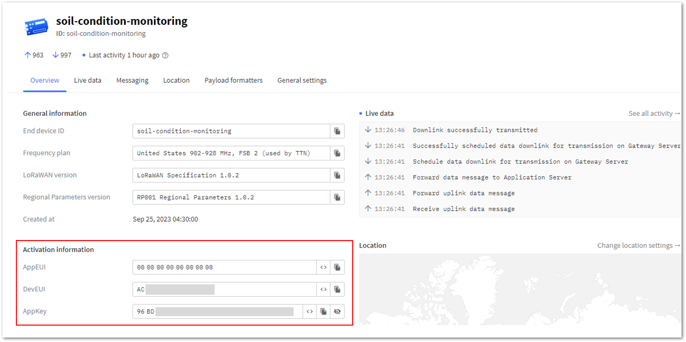 Figure 1: OTAA device successfully registered to TTN
- Once you're done with the code, proceed with uploading it to your device. Choose your RAK4631 board on your desktop or laptop. To do so, navigate to Tools > Board: XXXXX > RAKwireless nRF Boards, and select WisBlock RAK4631.
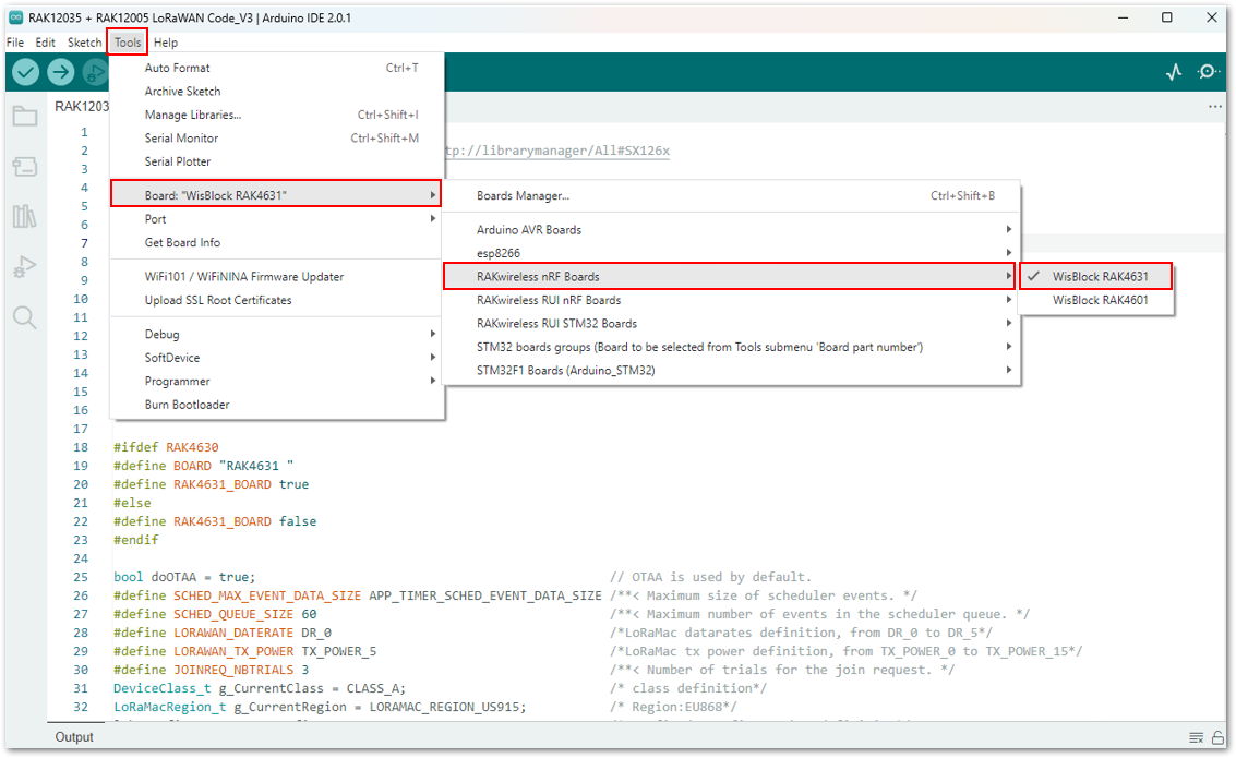 Figure 1: Selecting the RAK4631 board
- Go to Tools > Port and then select the specific port of your board.
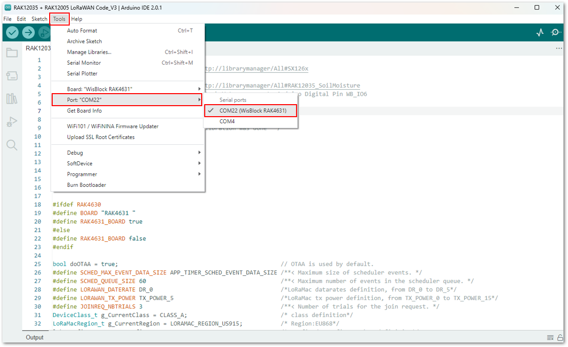 Figure 1: Selecting the port of RAK4631 board
- Upload the code by clicking the Upload button
 .
.
Once completed, the Device programmed notification will appear in the console at the bottom of the Arduino IDE.
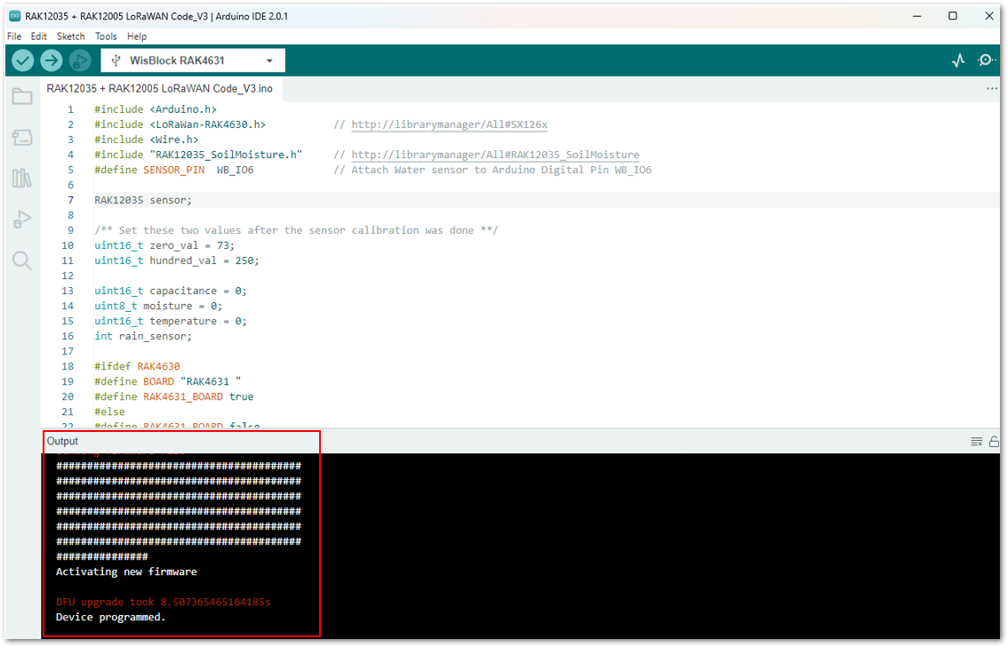 Figure 1: Arduino code is successfully uploaded into your RAK4631 board
Soil Condition Monitoring via TTN
- To monitor the data of your Soil Condition Monitoring device via TTN, go back to your TTN account where you created your application and registered your device.
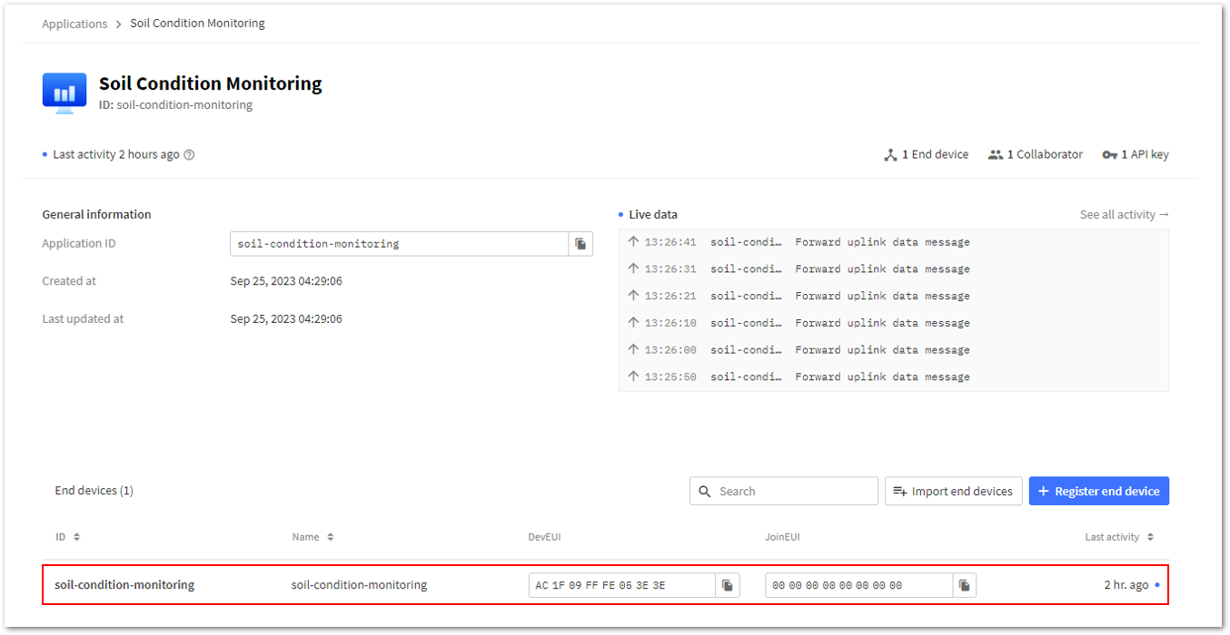 Figure 1: Your Soil Condition Monitoring device in TTN
- Then, go to Payload formatters. Under Formatter type, select Custom Javascript formatter.
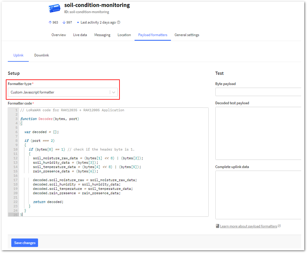 Figure 1: Payload Formatter
- Under the Formatter code field, replace the default code with the code given below. This decodes data transmitted from your device to TTN. Once done, simply click Save changes.
// LoRaWAN code for RAK12035 + RAK12005 Application

function Decoder(bytes, port)
{

  var decoded = {};

  if (port === 2)
  {
    if (bytes[0] == 1) // check if the header byte is 1.
    {
      soil_moisture_raw_data = (bytes[1] << 8) | (bytes[2]);
      soil_humidity_data = (bytes[3]);
      soil_temperature_data = (bytes[4] << 8) | (bytes[5]);
      rain_presence_data = (bytes[6]);

      decoded.soil_moisture_raw = soil_moisture_raw_data;
      decoded.soil_humidity = soil_humidity_data;
      decoded.soil_temperature = soil_temperature_data;
      decoded.rain_presence = rain_presence_data;

      return decoded;
    }
  }
}
- Go back to Live data of your device in TTN and compare it with the live data from the Serial Monitor of your device. You should now see identical results between them.
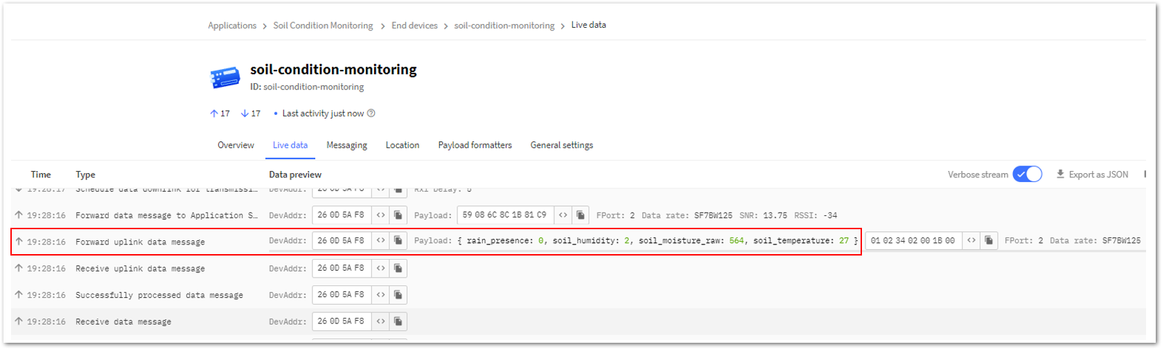 Figure 1: Live data from your device in TTN
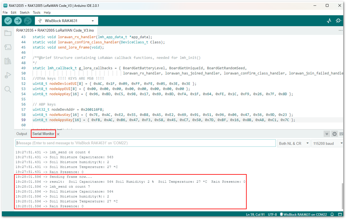 Figure 1: Live data from your device in its Serial Monitor
Soil Condition Monitoring via Akenza Platform
This section will guide you on how to integrate your application using Akenza. Here's the outline of the guide:
- Create an Account and Workplace
- Setup Connectivity Integration
- Add Device Connectors
- Create the Device Type
- Create a Dashboard
- Go to Akenza Portal and register to create your account.
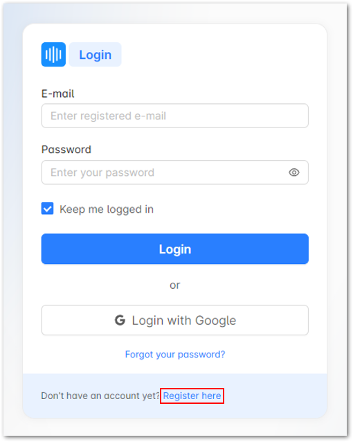 Figure 1: Creating Akenza Account
- After completing the account registration, log in to your Akenza Account. Configure your setup, and then select Create Workspace.
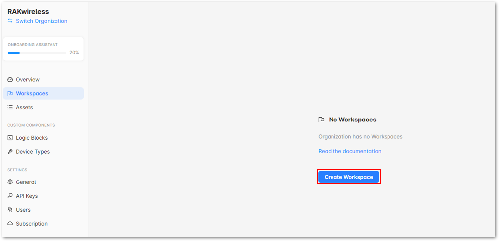 Figure 1: Create a Workspace
- On the pop-up window, provide details such as your workspace Name and its description. Then click Create Workspace.
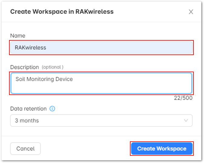 Figure 1: Create a Workspace
- You should be able to see a RAKwireless Workspace successfully created.
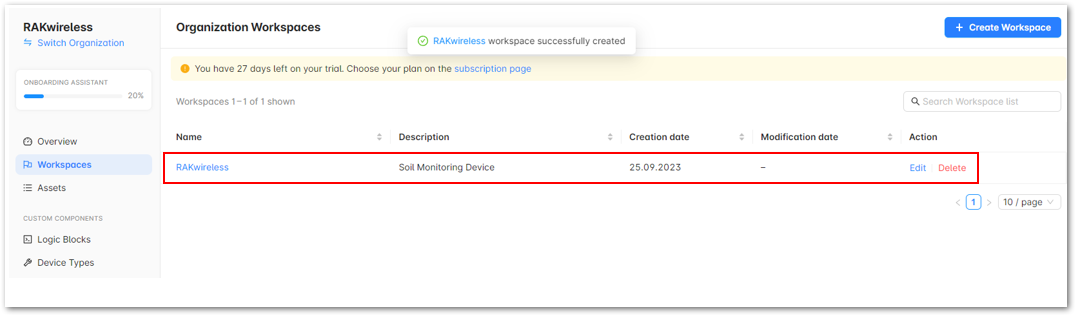 Figure 1: Workspace successfully created
After successfully creating the Workspace, connect your workspace to The Things Stack.
To do so, execute the following steps:
- On the left panel, navigate to Integrations, then click Create Integration button.
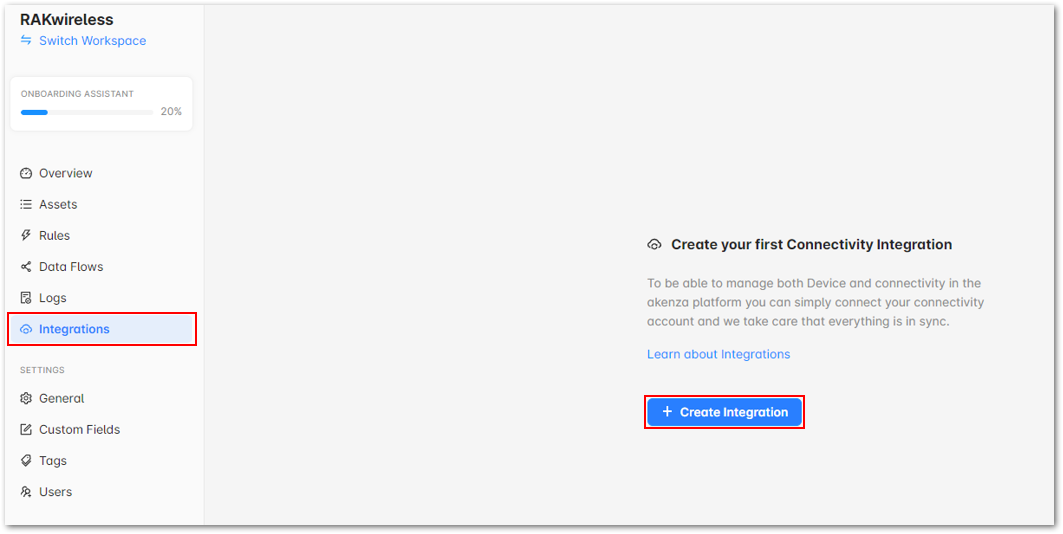 Figure 1: Create your first Connectivity Integration
- It will show the different Connectivity Integration setup. For this guide, choose The Things Stack.
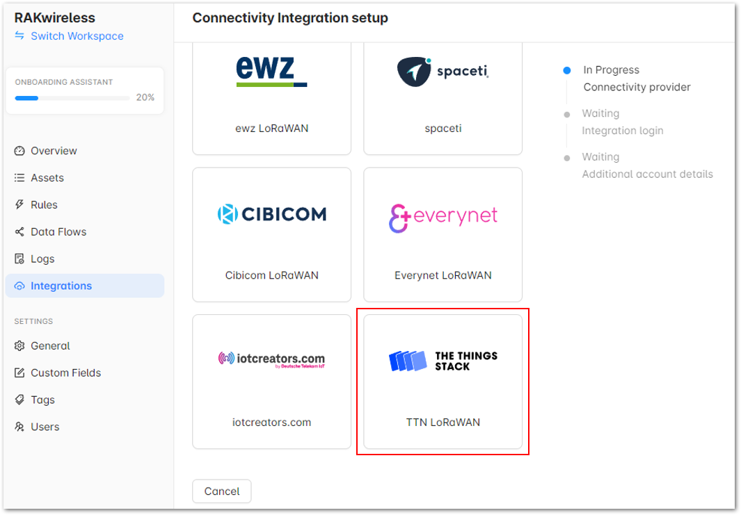 Figure 1: The Things Stack
- Setup your first Connectivity Integration by following the steps below:
- Under TTN LoRaWAN host in the Integration login section, choose the appropriate community to which you belong.
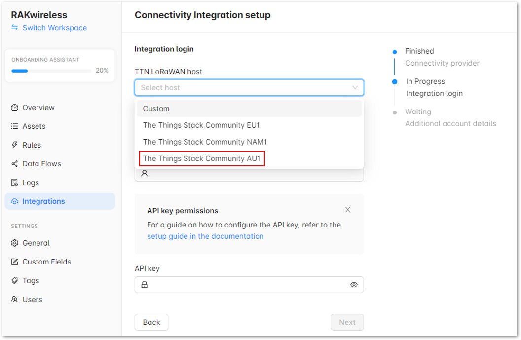 Figure 1: TTN LoRaWAN host
- In the Authentication field, select Application ID / API Key in the drop-down menu.
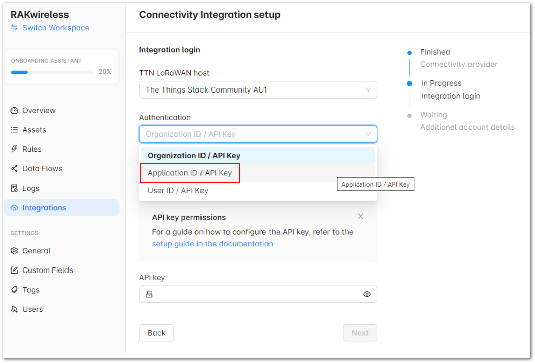 Figure 1: Authentication
- For the Application ID, copy the TTN Application ID and then paste it to your Akenza workspace.
a. Navigate to your TTN Applications, and select Soil Condition Monitoring
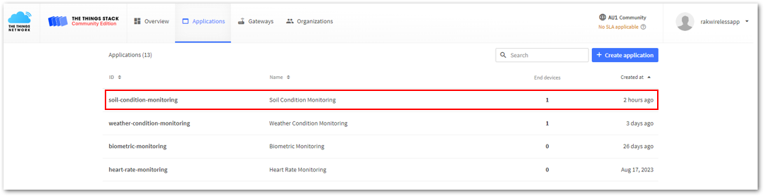 Figure 1: Applications in TTN
b. In the Overview page of your application, copy Application ID.
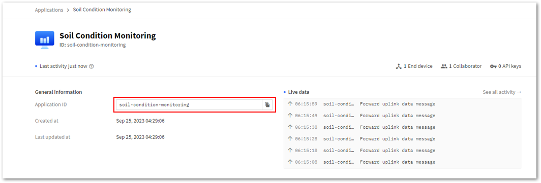 Figure 1: Copying the Application ID of your application in TTN
c. Paste the copied application ID into your Akenza workspace Application ID field.
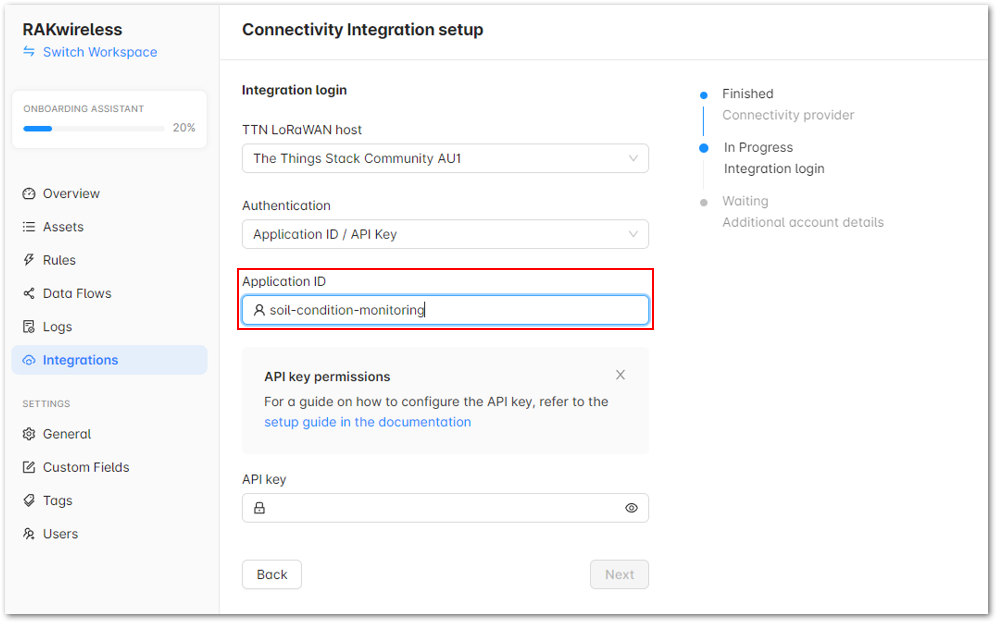 Figure 1: Pasting the Application ID in your Akenza workspace
- Finally, for the API keys, follow the steps below:
a. Go back to your TTN Applications, and select Soil Condition Monitoring. In the left panel, click API keys.
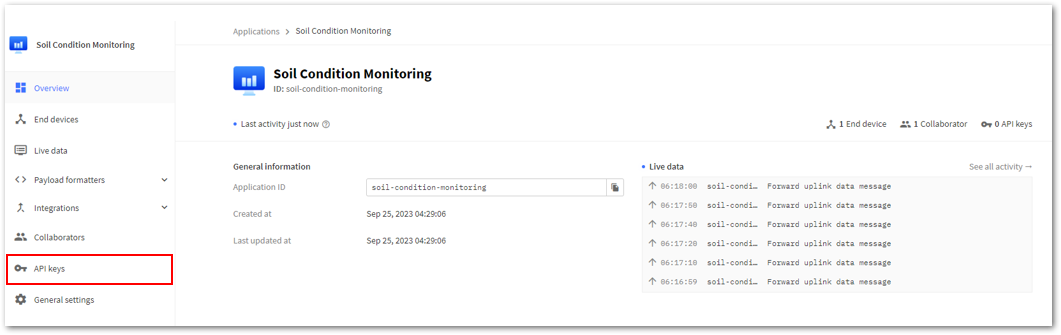 Figure 1: API keys
b. Click on the Add API key button.
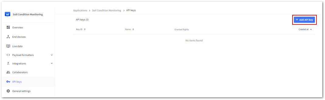 Figure 1: Add API key
c. Enter the Name and select the Rights, then click Create API key.
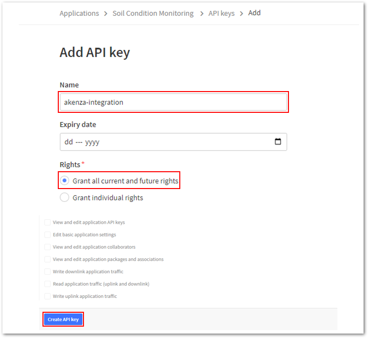 Figure 1: API key creation
d. Once done, copy the created API key and click I have copied the key.
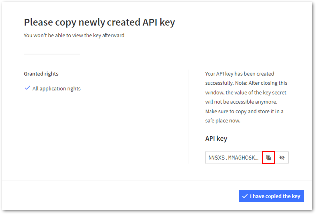 Figure 1: Created API key
e. Paste the API key from the TTN application to the API key field of your Akenza workspace. Then, click Next to proceed.
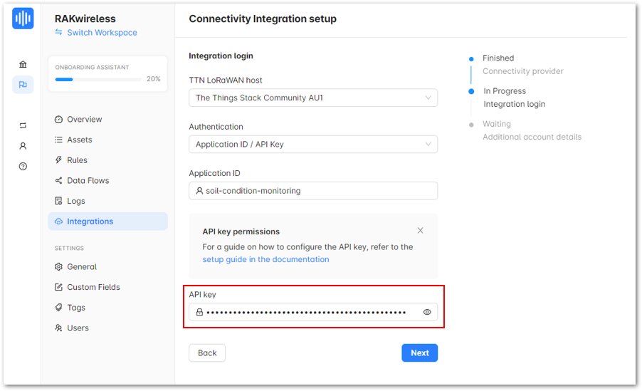 Figure 1: Akenza - API key
f. Under Additional account details, enter details in the Integration name field and then click Next.
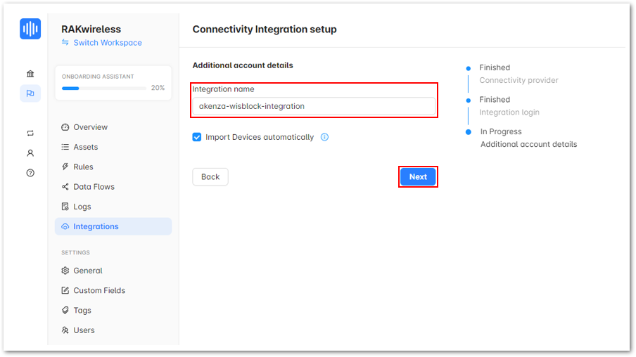 Figure 1: Integration name
g. Once done with the integration setup, click Done.
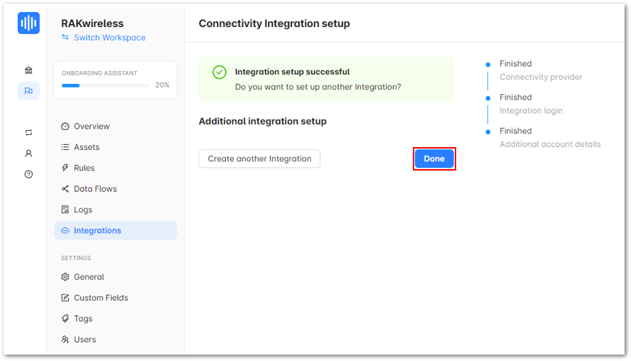 Figure 1: Successful Integration setup
h. After clicking Done your window should look like Figure 32.
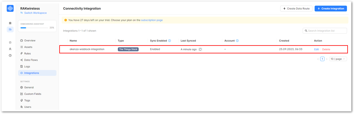 Figure 1: Successful Integration setup
i. Go back to your application in TTN and go to Integrations. You should see the created API key.
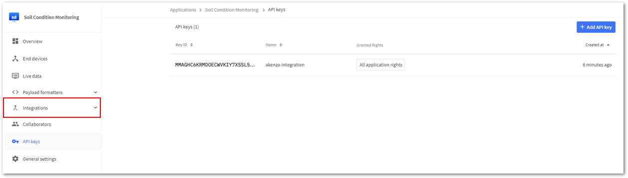 Figure 1: Integrations
j. After a successful Integration, expand the Integrations drop-down, and select Webhooks. You will notice that a webhook is already generated.
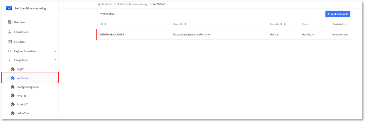 Figure 1: Webhooks
k. Go back to your Akenza workspace and click on Assets, then click on your device integrated with Akenza.
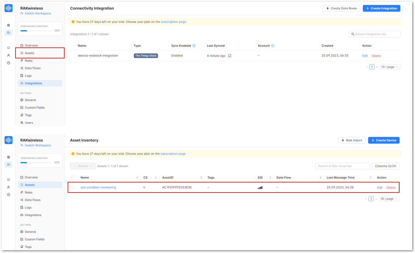 Figure 1: Your device integrated with Akenza
Device connectors define the protocol and authorization the device communicates with Akenza. Here are the steps on how to add Device connectors:
- Create a New Data Flow
- On the left panel, navigate to Data Flows, then click Create Data Flow button.
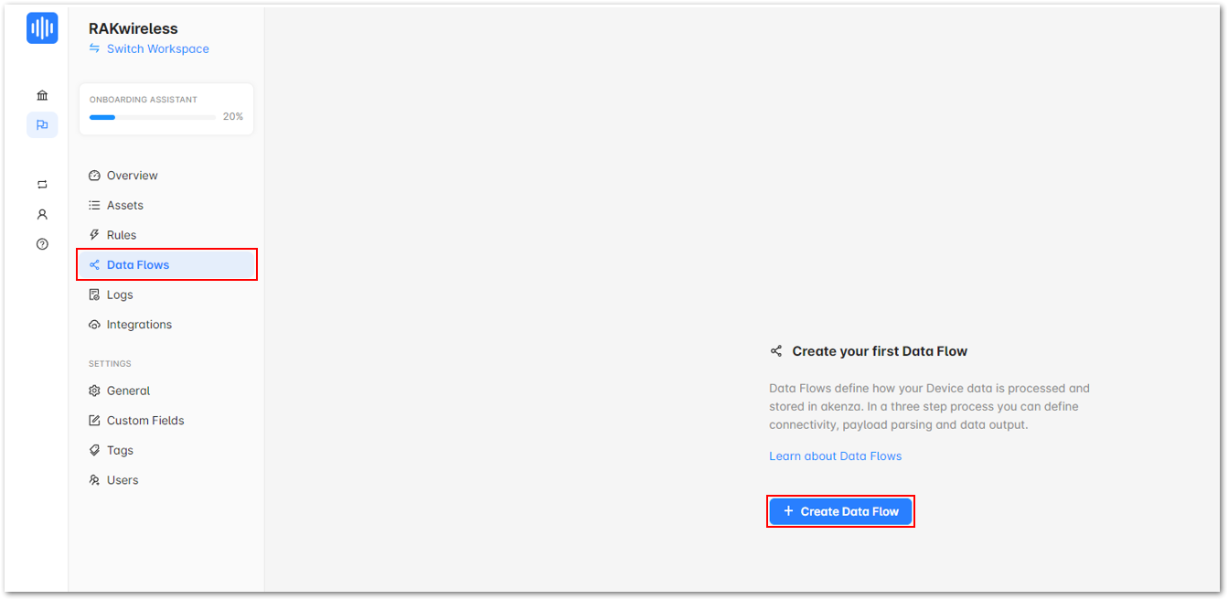 Figure 1: Create a Data Flow
- After that, click on Create new Data Flow.
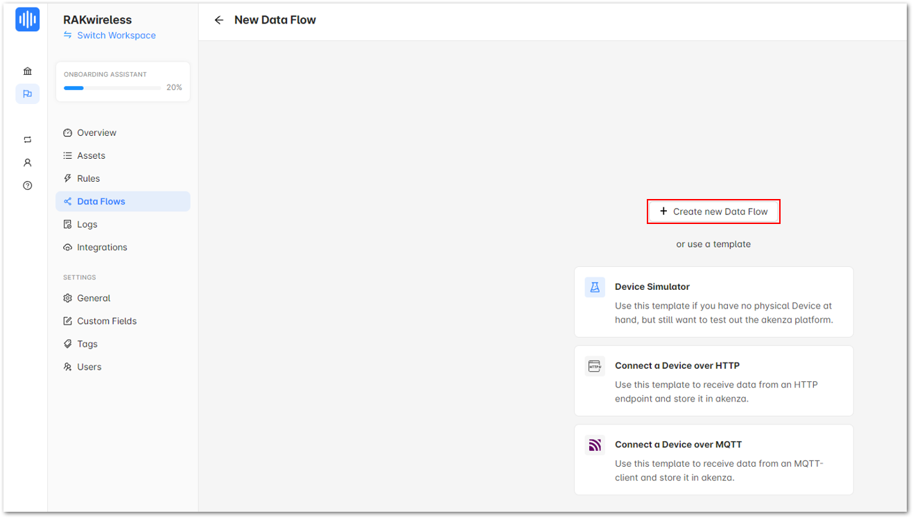 Figure 1: Create a new Data Flow
- Select and configure device connectivity.
- Click on Device Connector
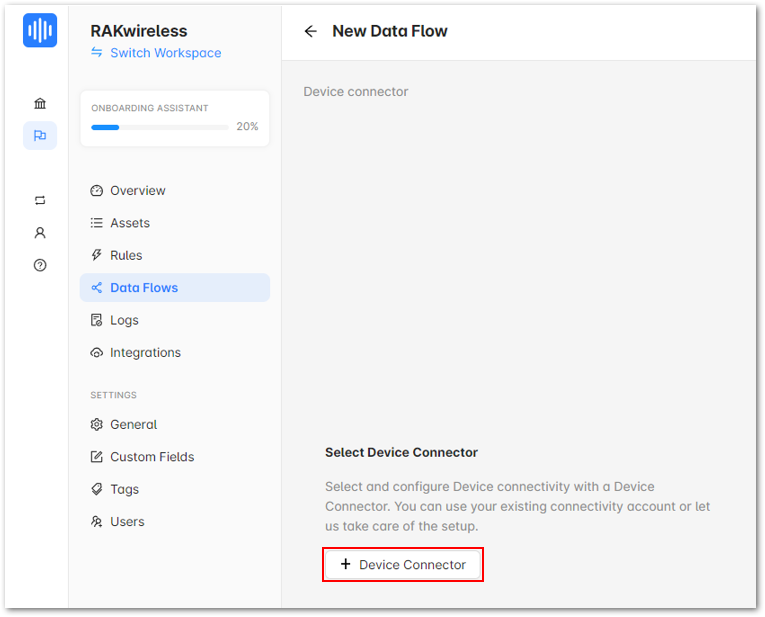 Figure 1: Device Connector
- It will show the various Device connectors. Choose LoRa for this guide.
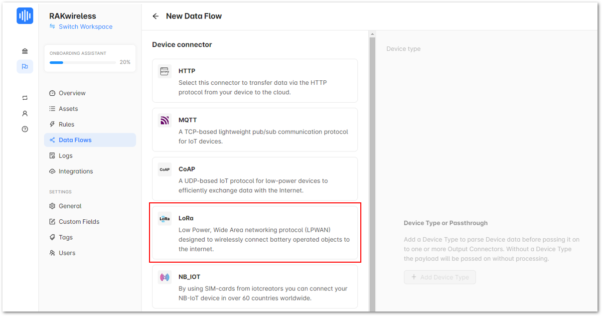 Figure 1: LoRa under Device connector
- After choosing LoRa, a list of LoRa Device connectors will appear. Choose The Things Stack.
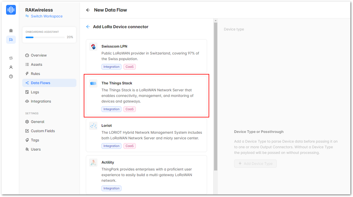 Figure 1: The Things Stack
- Then, click TTN Connector - akenza-wisblock-integration.
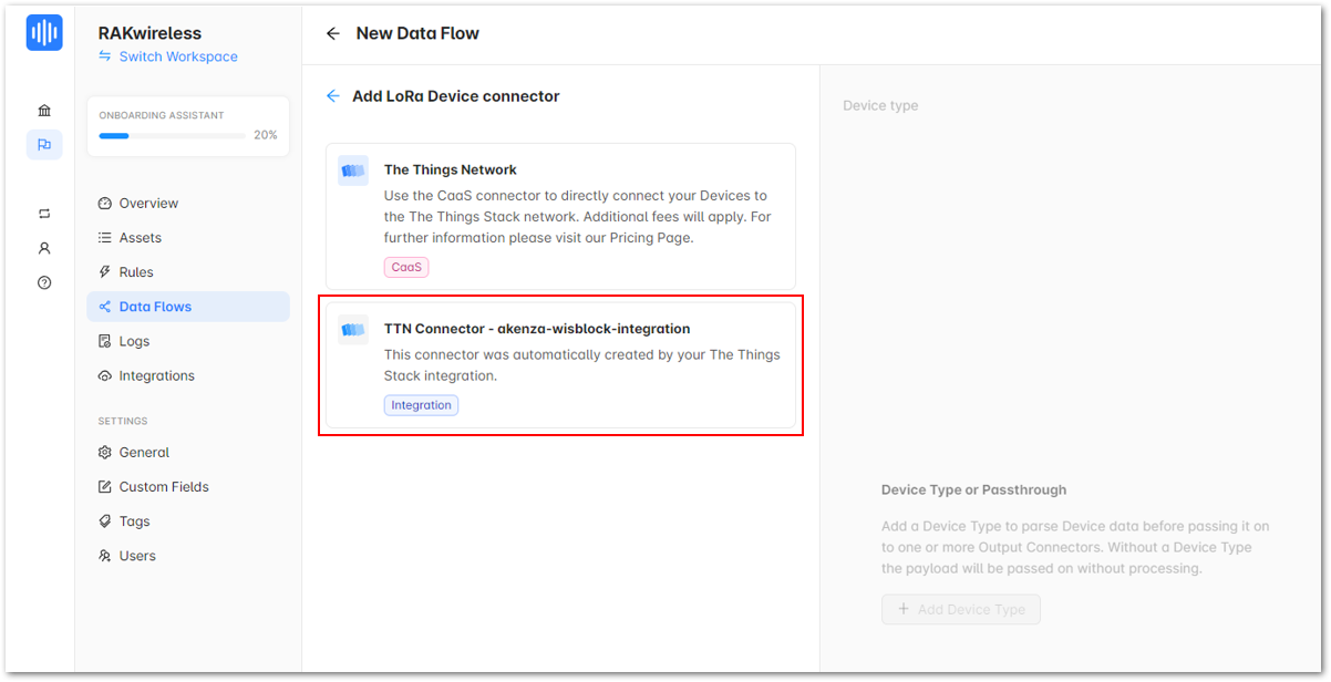 Figure 1: TTN Connector - akenza-wisblock-integration
- Configure the device data destinations.
- Click Add Output Connector.
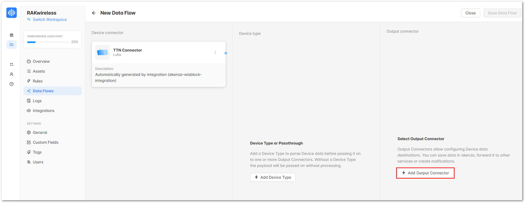 Figure 1: Add Output Connector
- Under Database, choose Akenza DB for this guide.
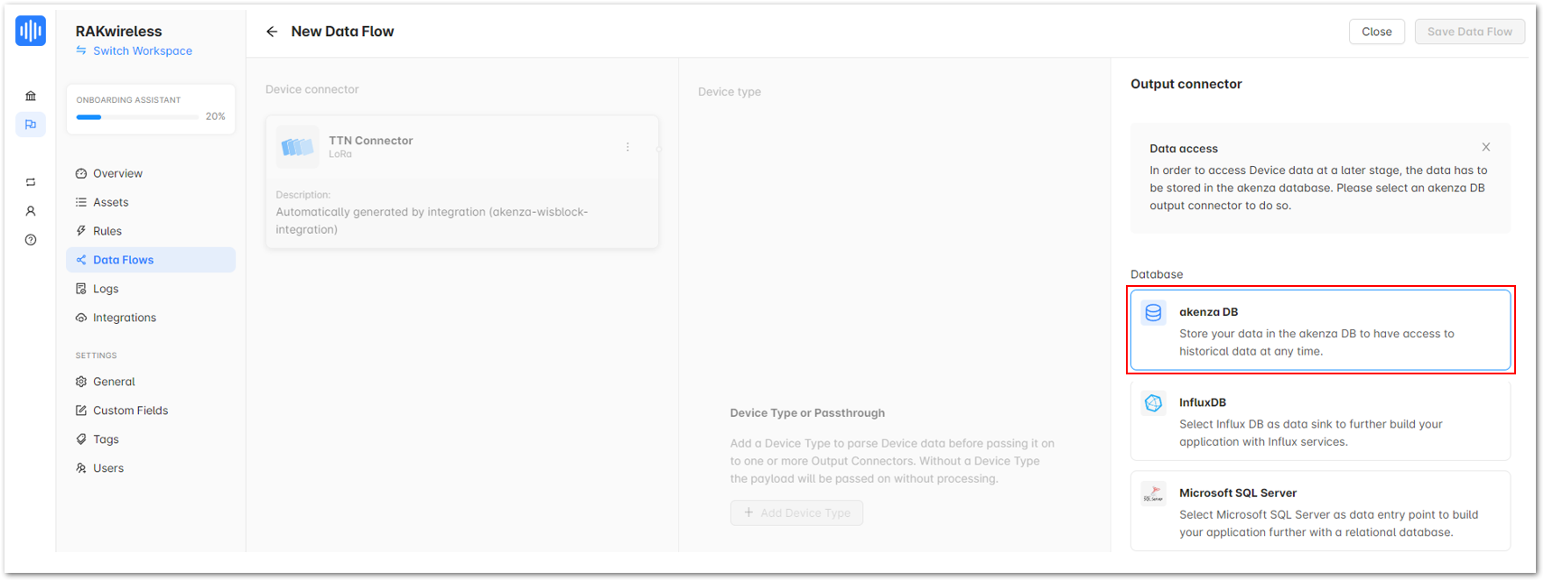 Figure 1: akenza DB
- Output connector is successfully added. Click Save Data Flow.
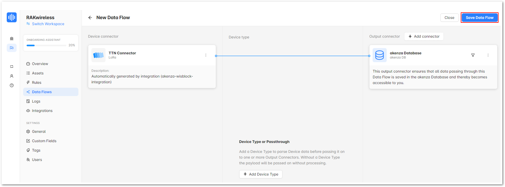 Figure 1: Save Data Flow
- Enter the Name on the popup window and click Save Data Flow.
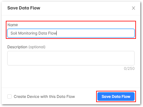 Figure 1: Save Data Flow
- Once you created the data flow, exit the window.
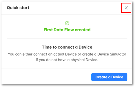 Figure 1: Quick start
- Set the Data Overview
- Go back to Assets.
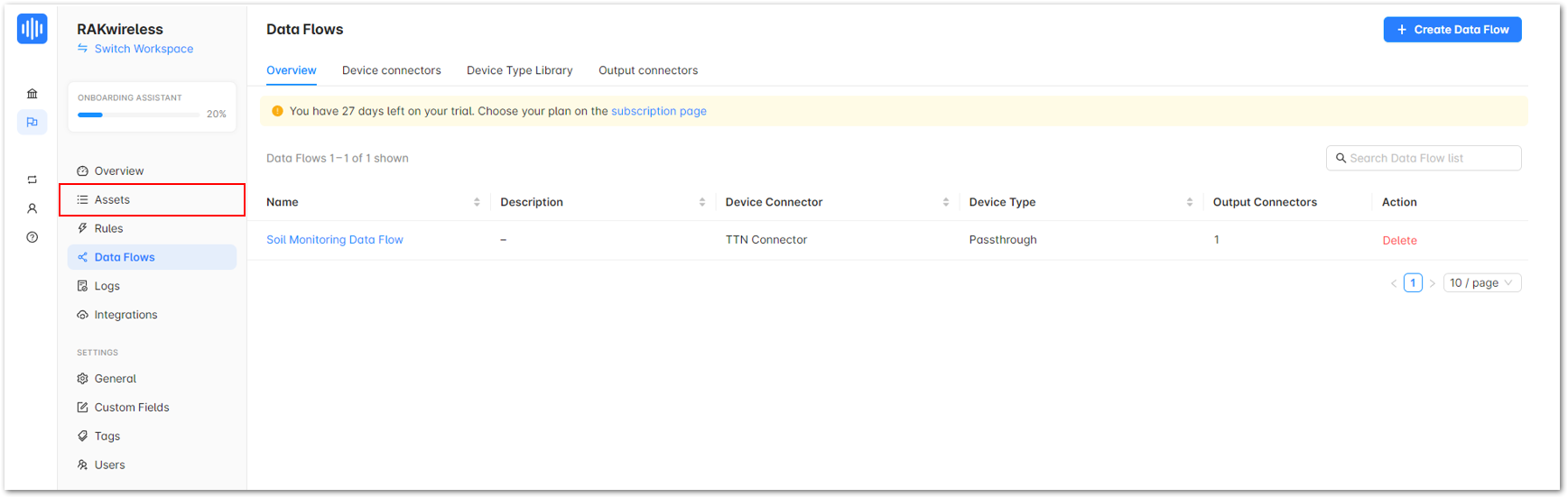 Figure 1: Assets
- Highlight your device integrated with Akenza.
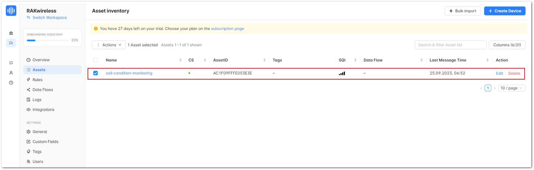 Figure 1: Your device integrated with Akenza
- Click on the drop down More, which is located on the upper right corner, then choose Edit.
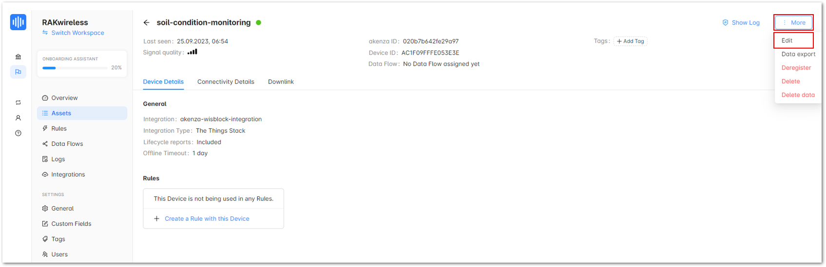 Figure 1: Your device integrated with Akenza
- Under Data Processing, click on Data Flow.
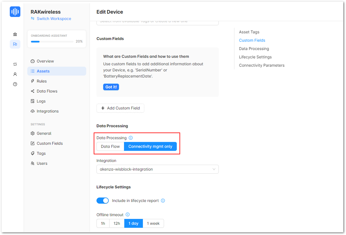 Figure 1: Data Flow
- Then, select the Data Flow of your device.
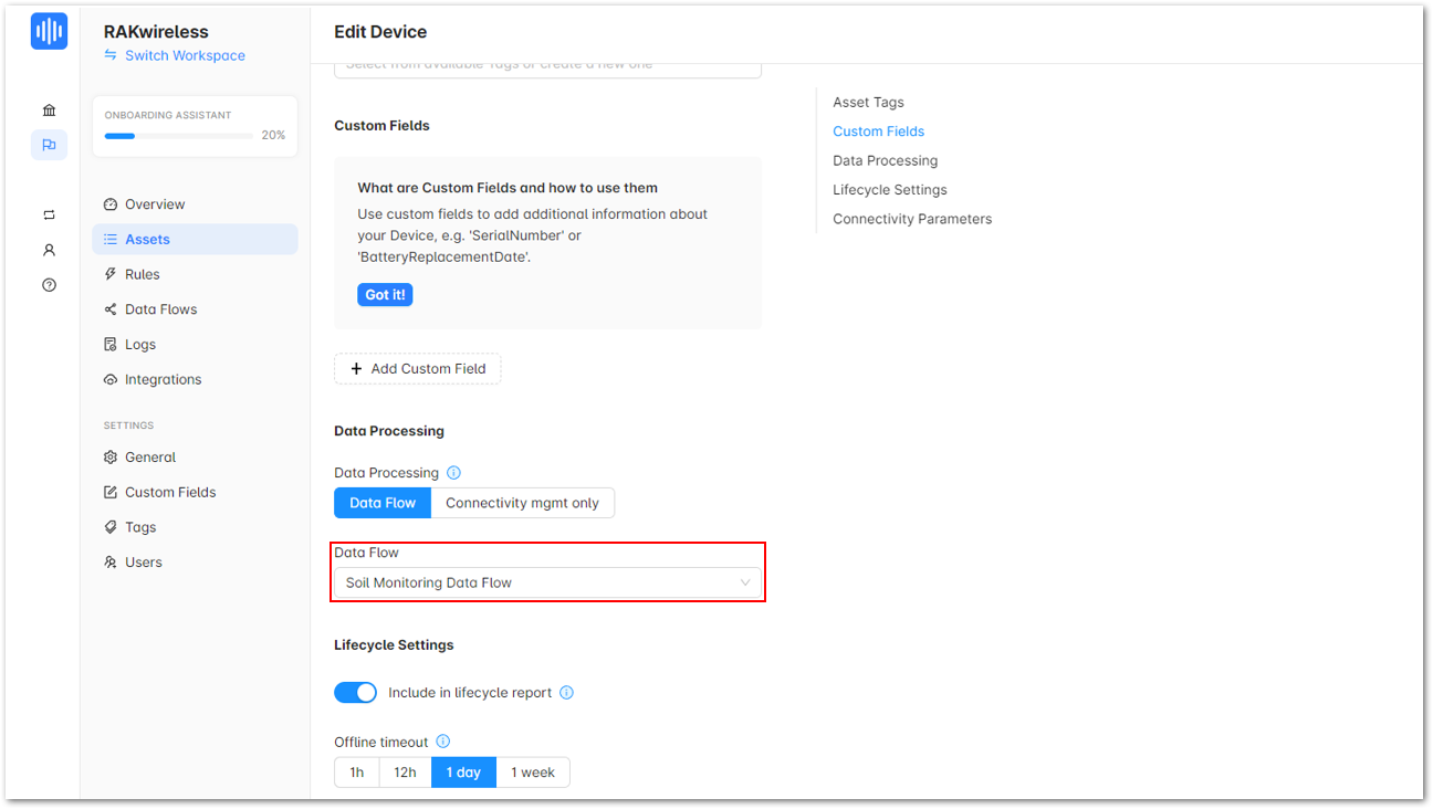 Figure 1: Data Flow
- Once done, click Update Device.
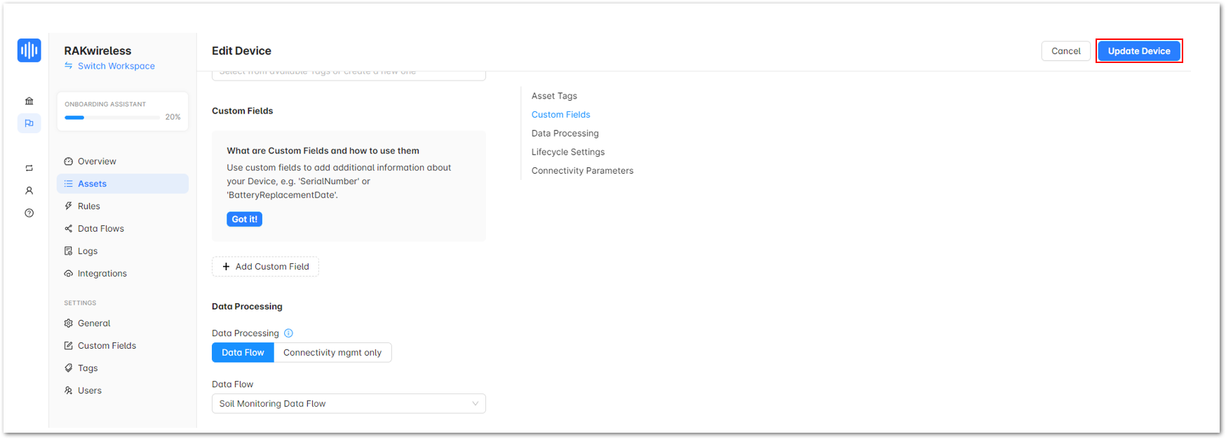 Figure 1: Update Device
- You should be now looking at the data overview of your device integrated with Akenza.
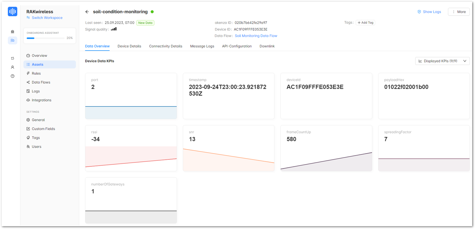 Figure 1: Data Overview
Device Types extract, transform and normalize the data sent from the device. These are the steps on how to add a Device Type:
- Go to Device Types and click Create Device Type.
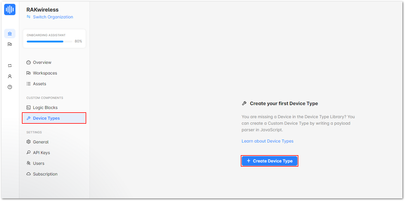 Figure 1: Create a Device Type
- Once done, provide details under Device type name then, click Next.
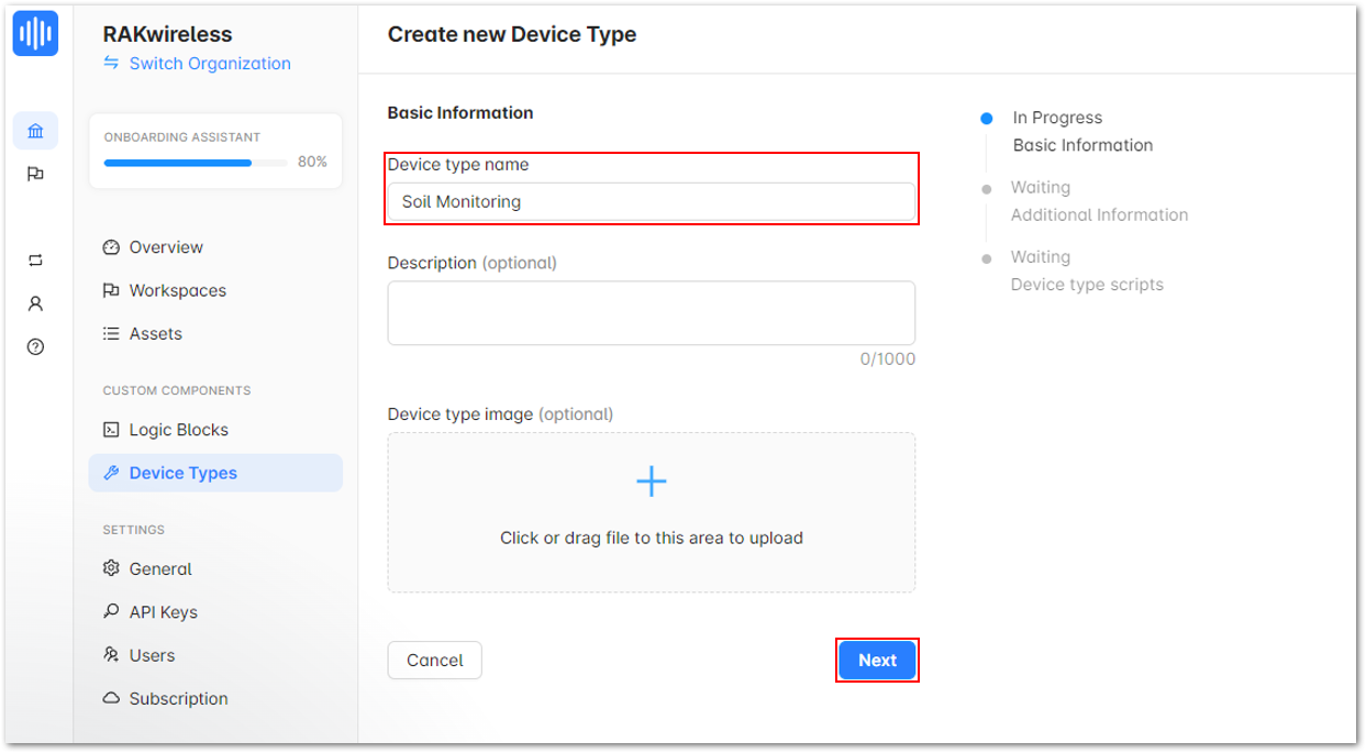 Figure 1: Device type name
- Then, on the next portion, click Next.
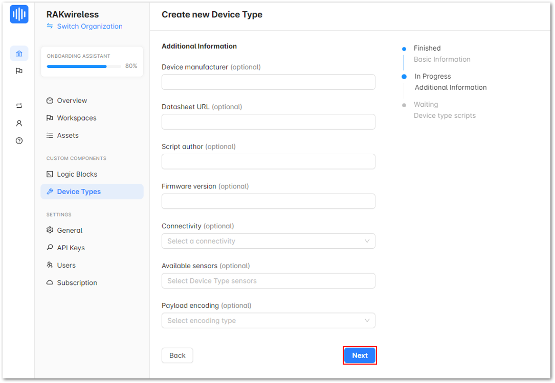 Figure 1: Other information of your device
- Click on Open script editor.
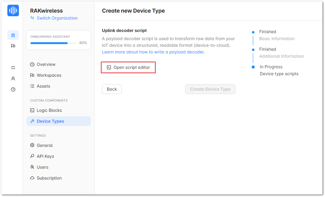 Figure 1: Open script editor
- Provide the decoder for your device.
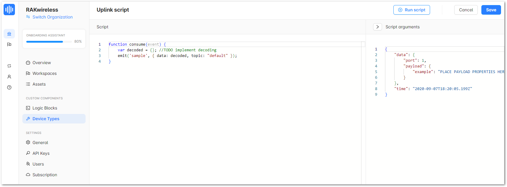 Figure 1: Uplink script
- Into the Uplink script, replace the default script with the code below:
function consume(event)
{
    const payload = event.data.payloadHex;
    const port = Number(event.data.port);
    const bytes = Hex.hexToBytes(payload);

    const decoded = Decoder(bytes, port);

    emit('sample', { data: decoded, topic: "default" });
}
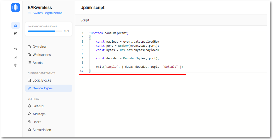 Figure 1: Uplink script
- Go back to your application in TTN and copy the decoder in the Payload formatters.
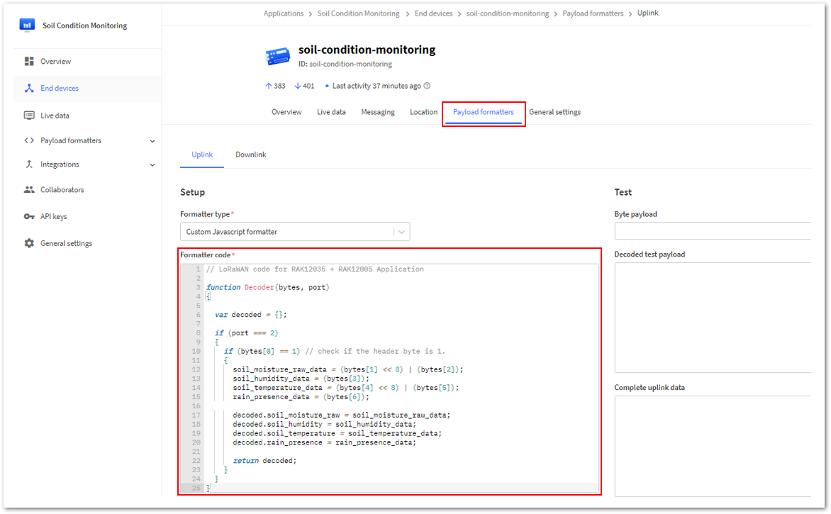 Figure 1: Decoder of your Soil Monitoring device in TTN
- Go back to Akenza and paste it on the next lines of the Uplink script.
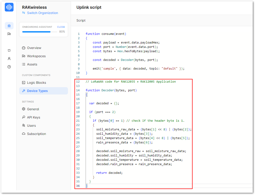 Figure 1: Uplink script
- Insert the word "let" at the beginning of every variable and rearrange the code in the sequence shown in Figure 62. Finally, click Save.
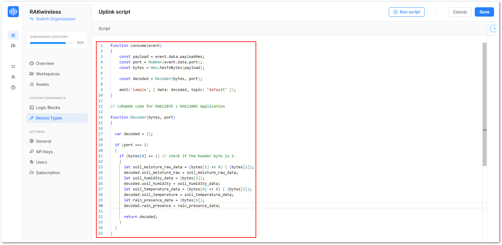 Figure 1: Modified script
- Once done, go to Data Flows and click on your device's data flow.
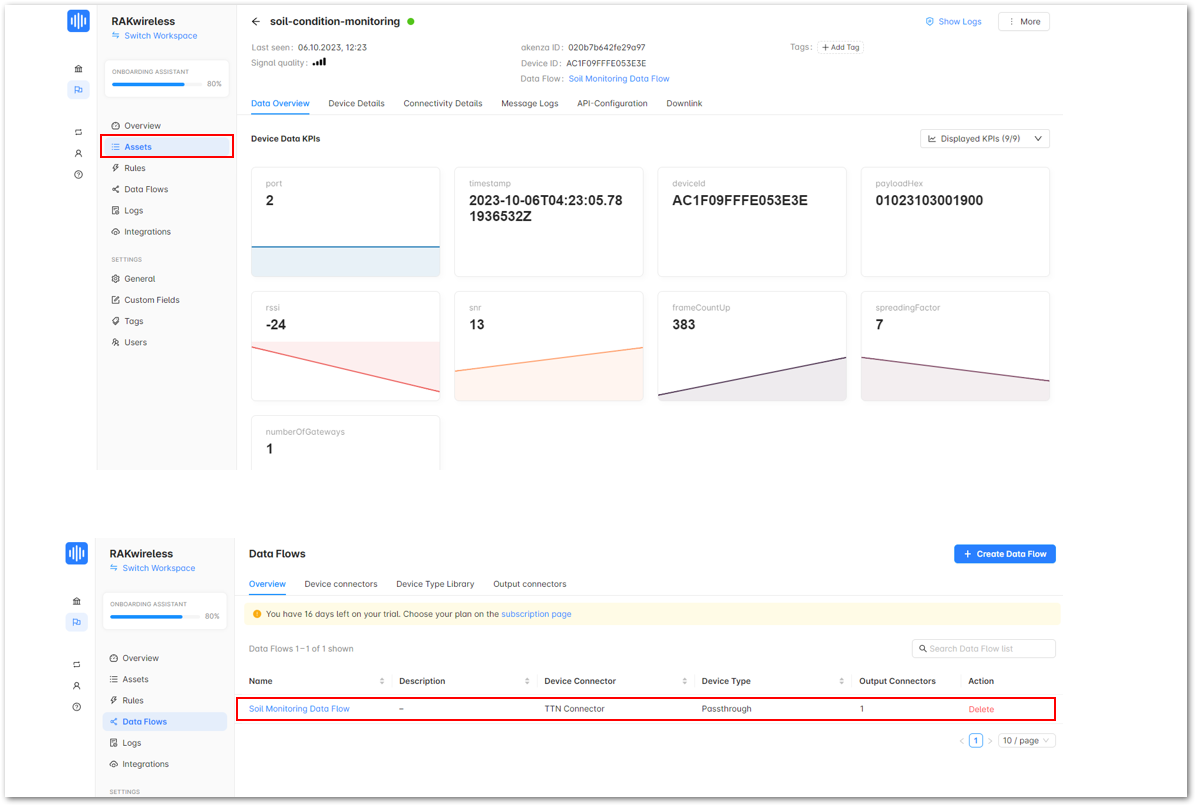 Figure 1: Your device's data flow
- Click Add Device Type, to select your custom device.
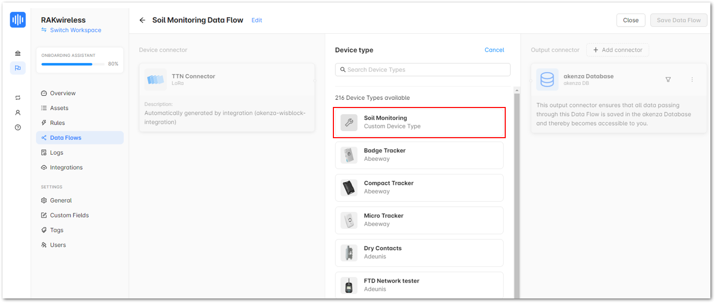 Figure 1: Soil Monitoring device
- Once done, click Save Data Flow.
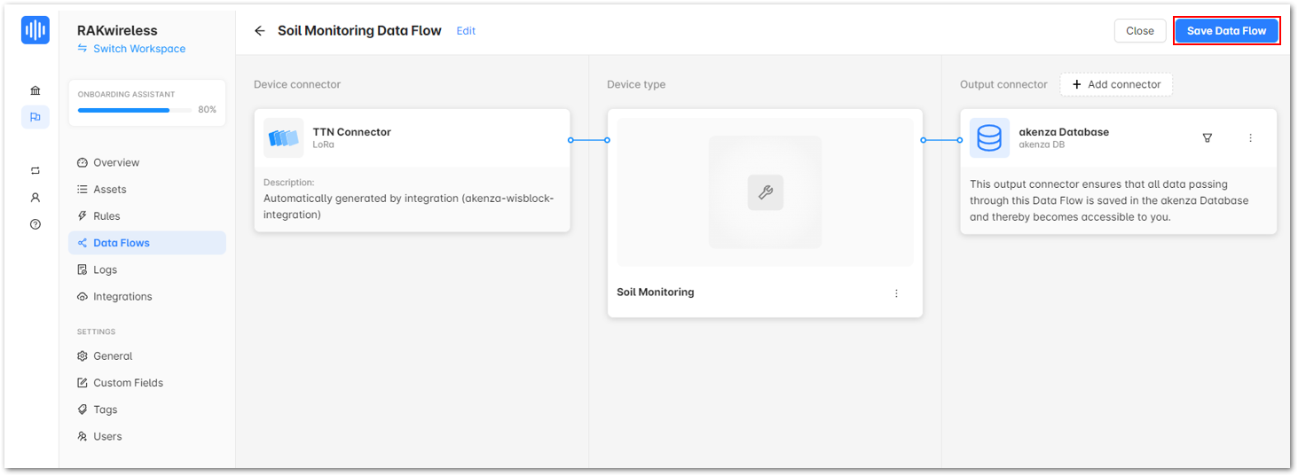 Figure 1: Save Data Flow
- Go to Assets and click on your device.
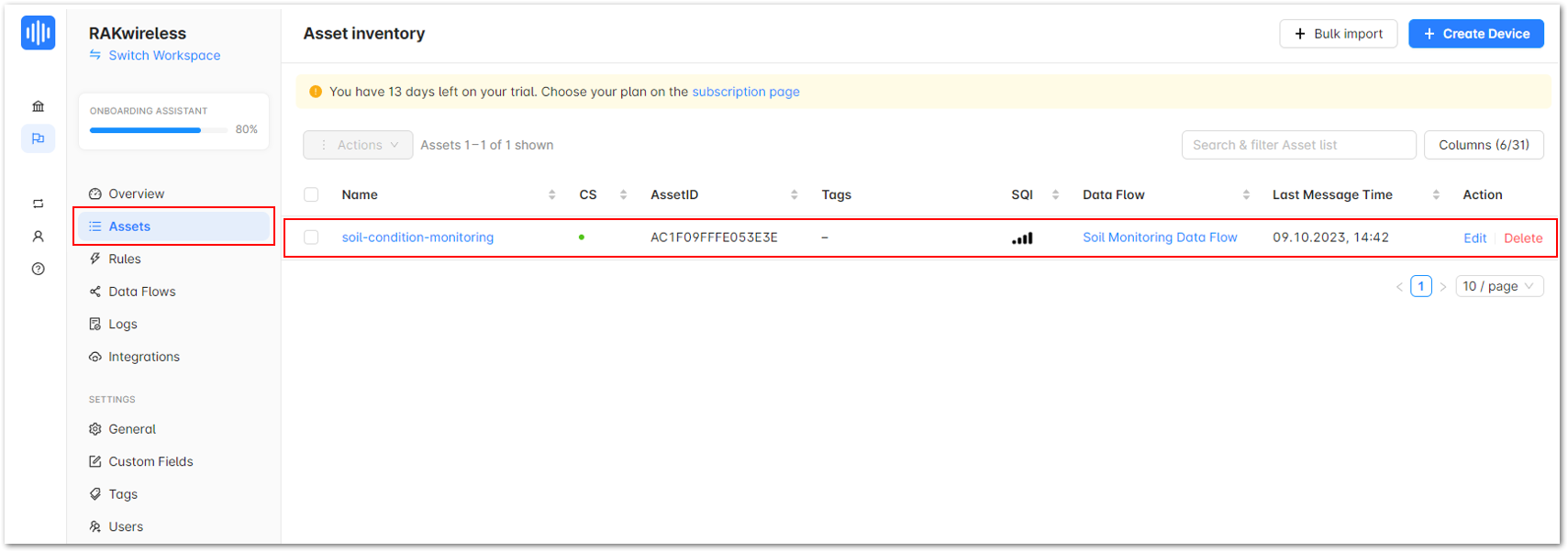 Figure 1: Assets
- You should now see a working Soil Monitoring workspace in Akenza showing the data from your Soil Monitoring device.
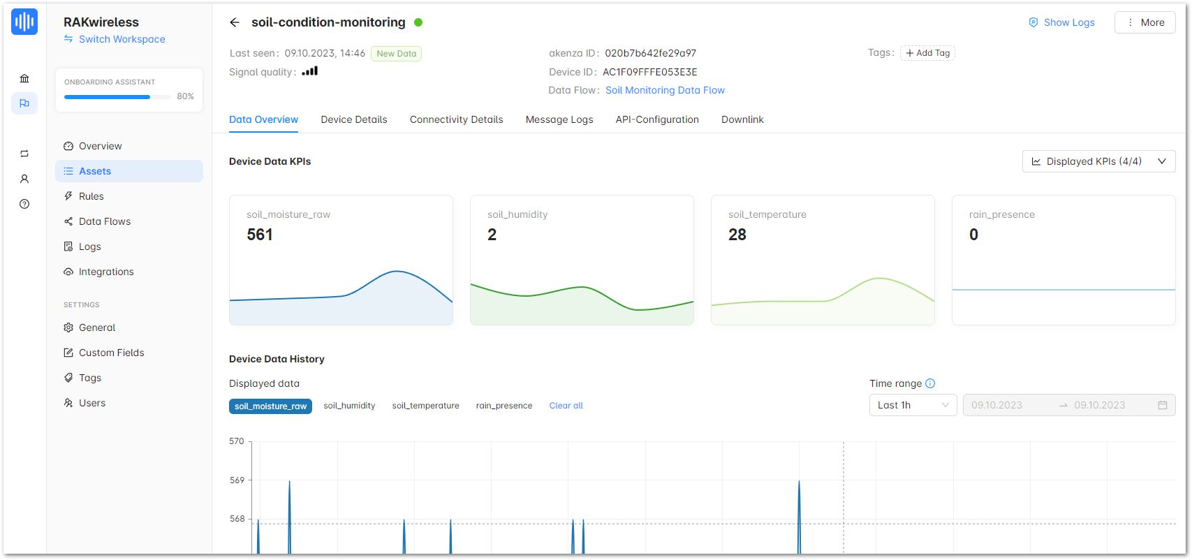 Figure 1: Your device's data overview
The dashboard builder makes it easy to create custom dashboards and display data stored in Akenza. These are the steps on how to create a working dashboard for your Soil Monitoring device:
- Access to the Dashboard module a. Click on Home, then go to Device Management > Dashboard Builder.
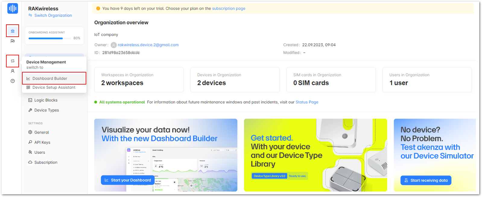 Figure 1: Dashboard Builder
b. Click Create a Dashboard.
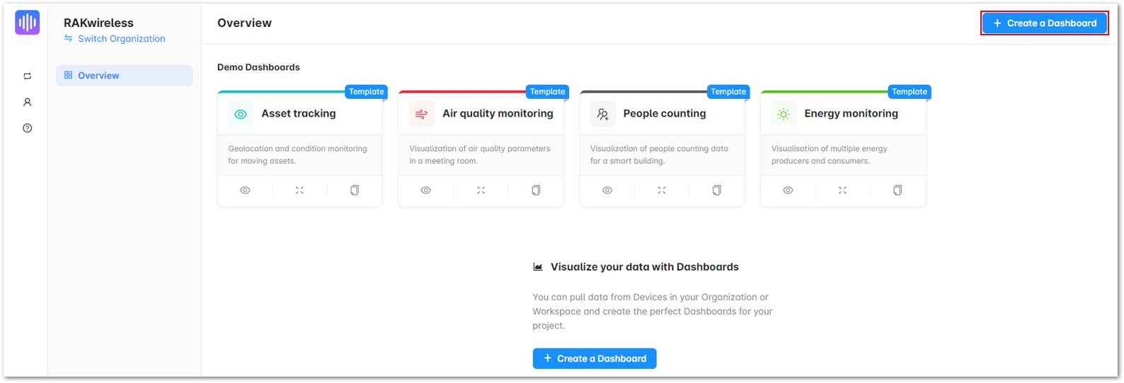 Figure 1: Create a Dashboard
- Configure Dashboard Settings a. Enter the desired Name for your application, then click Next.
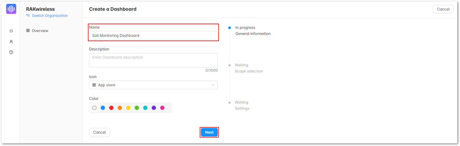 Figure 1: Create a Dashboard
b. Select the specific workspace of your application and click Next.
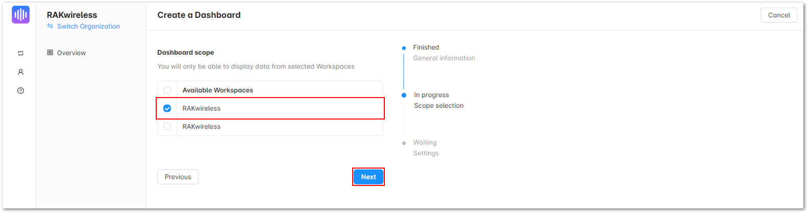 Figure 1: Create a Dashboard
c. Under Refresh interval, choose 1 min to load the latest data for every 1 minute. Click Create a Dashboard.
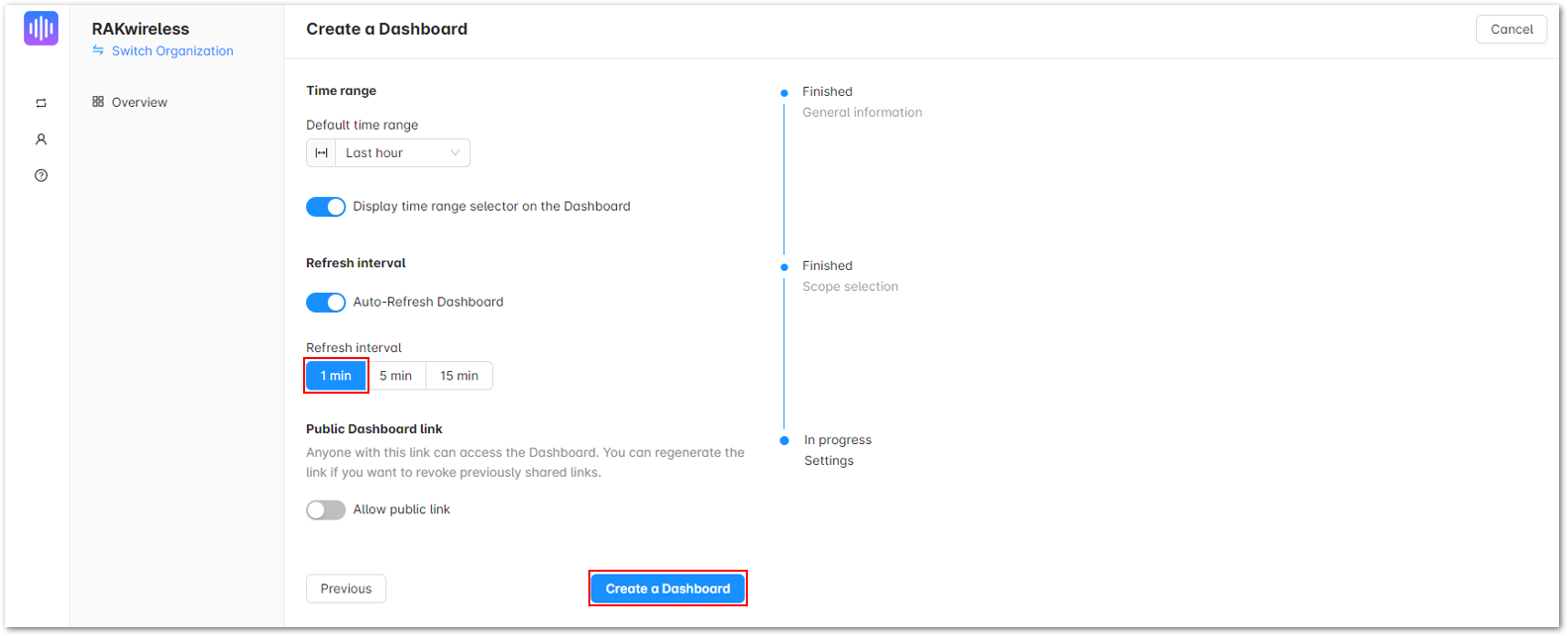 Figure 1: Create a Dashboard
- Add Components a.Once you have created your dashboard, click Add Component. In the dropdown menu, select Chart.
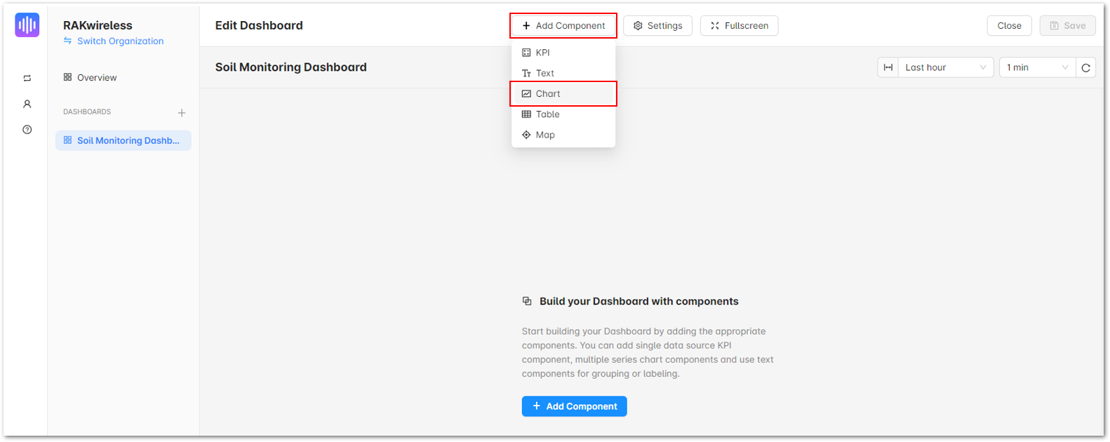 Figure 1: Soil Monitoring Dashboard
b. Under the Content tab, on the Heading field, input the details of the parameter you will monitor.
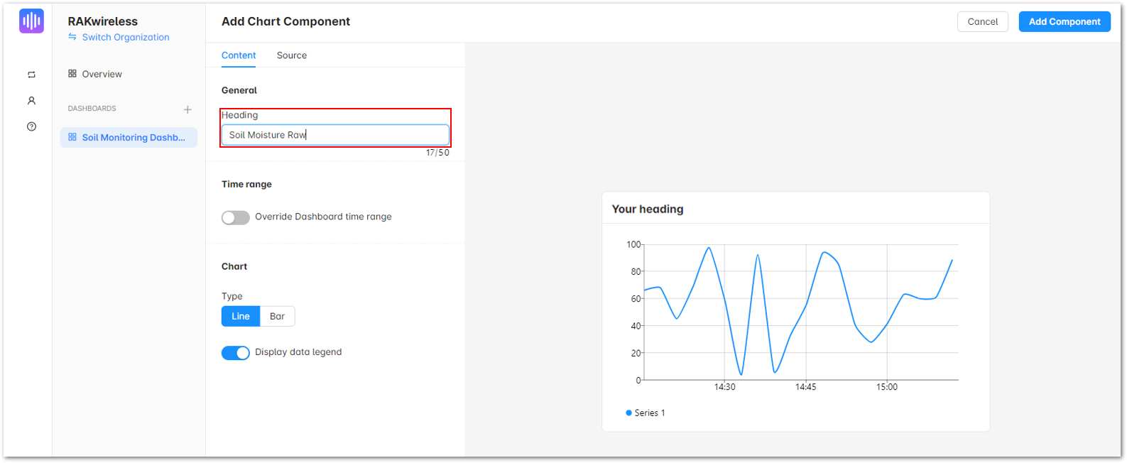 Figure 1: Chart Component
c. Click on the Source tab, select your Soil Monitoring device on the Device field.
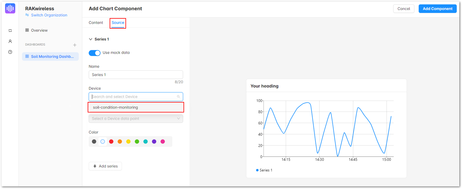 Figure 1: Chart Component
d. Move to the Data Point field, select the Default option, and choose the specific parameter for your chart.
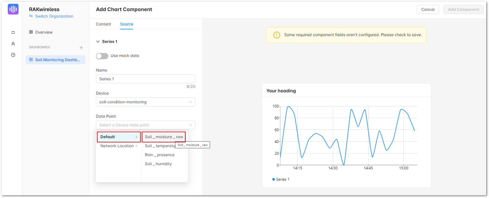 Figure 1: Chart Component
e. Once done, click Add Component.
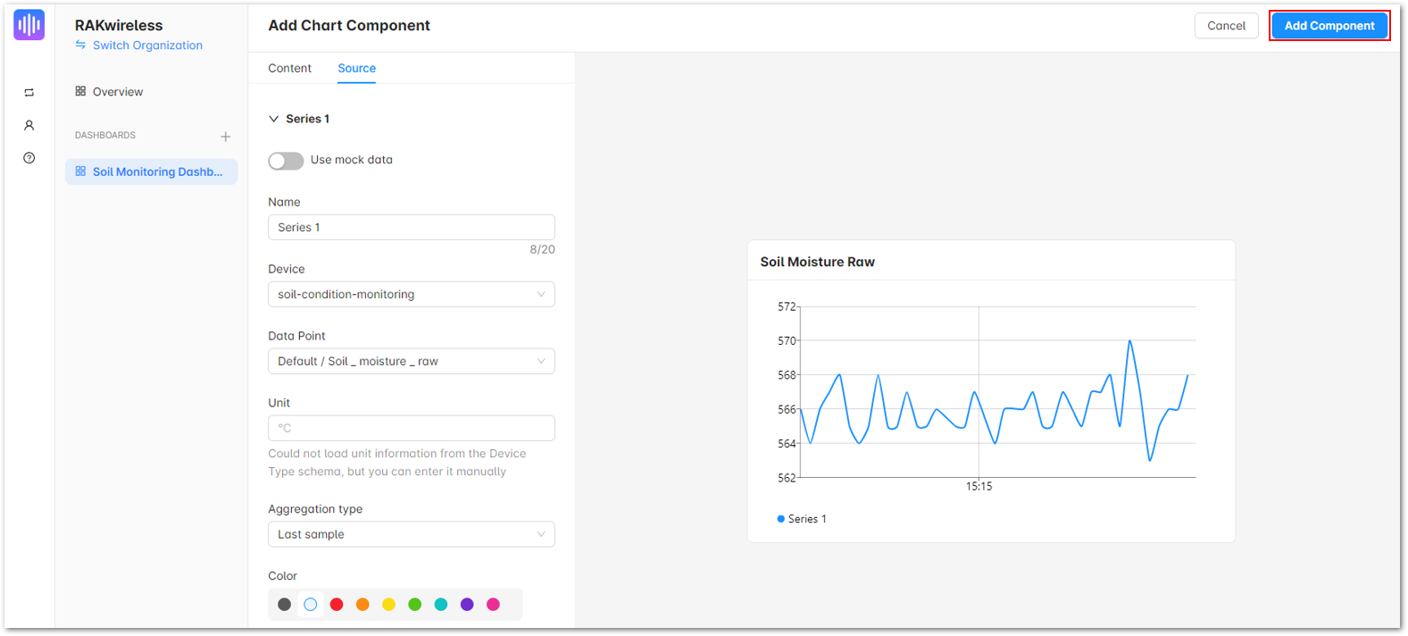 Figure 1: Chart Component
- To add charts for other parameters to be included in the dashboard, just repeat Step 3 then click Save.
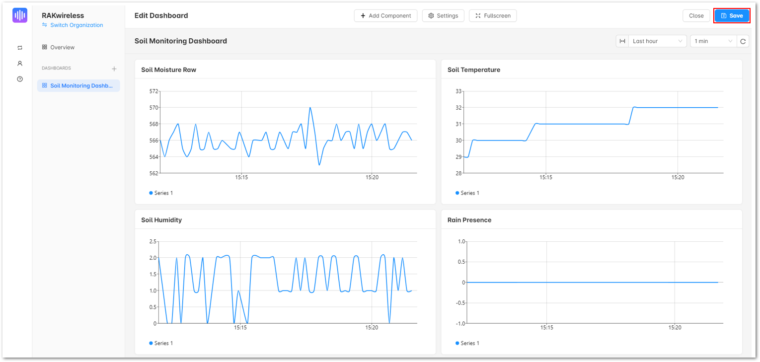 Figure 1: Saving your dashboard
- You should be able to see a working dashboard for your Soil Monitoring device.
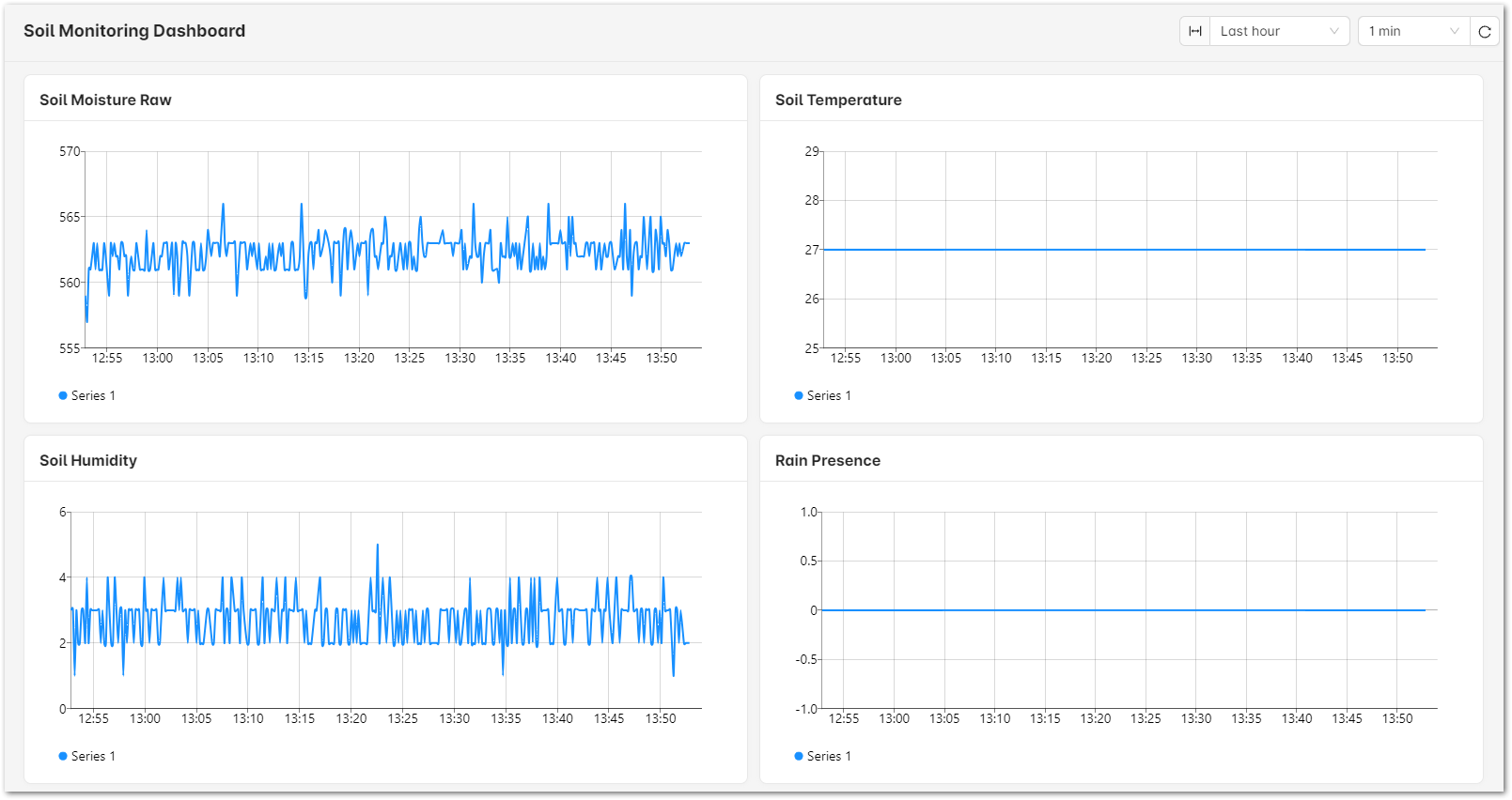 Figure 1: Soil Monitoring Dashboard
Weather Condition Monitoring LoRaWAN Application
The Weather Condition Monitoring LoRaWAN Application is used to monitor the weather conditions via several sensor modules. It utilizes RAK1906 to measure the temperature and humidity of the environment, RAK12010 to measure light intensity, and RAK12019 to measure the UV index from sun exposure. This integrated monitoring device will aid in monitoring the farm environment.
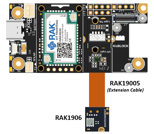 Figure 1: Weather Monitoring Device
Weather Condition Monitoring - TTN Registration Section and Device Registration
- If you already have an existing TTN account, you may proceed to the next steps. If you do not have an account yet, go to the The Things Network Configuration section and create one.
- Once done with the TTN account creation, proceed to the OTAA Device Registration section. After creating the application and adding the device in TTN, you can proceed on the LoRaWAN Code uploading steps.
LoRaWAN Code for Weather Condition Monitoring
- If you already have Arduino IDE installed on your laptop or PC and have added the RAK4631 board to it, you may proceed to the next step. If you have not yet installed the Arduino IDE, go to the RAK4631 Installation section and follow the steps provided.
- After the installation, you can now proceed programming your Weather Condition Monitoring device. Simply copy the Weather Condition Monitoring LoRaWAN Application code below and paste it into the Arduino IDE.
The example code uses SX126x-Arduino library which needs to be added to successfully compile the LoRaWAN code.
Click to view the example
#include <Arduino.h>
#include <LoRaWan-RAK4630.h>               // http://librarymanager/All#SX126x
#include <SPI.h>
#include <Wire.h>
#include "UVlight_LTR390.h"                // http://librarymanager/All#RAK12019_LTR390
#include "Light_VEML7700.h"                // http://librarymanager/All#Light_veml7700
#include <Adafruit_Sensor.h>
#include <Adafruit_BME680.h>               // http://librarymanager/All#Adafruit_BME680

UVlight_LTR390 ltr = UVlight_LTR390();
Light_VEML7700 VMEL = Light_VEML7700();
Adafruit_BME680 bme;
#define SEALEVELPRESSURE_HPA (1010.0)      // Adjustment might be needed in this parameter

uint16_t uvi;
uint32_t uvs;
uint32_t lux;
uint32_t white;
uint32_t raw_als;
float temperature;
float pressure;
float humidity;
float gas_resistance;

#ifdef RAK4630
#define BOARD "RAK4631 "
#define RAK4631_BOARD true
#else
#define RAK4631_BOARD false
#endif

bool doOTAA = true;                                               // OTAA is used by default.
#define SCHED_MAX_EVENT_DATA_SIZE APP_TIMER_SCHED_EVENT_DATA_SIZE /**< Maximum size of scheduler events. */
#define SCHED_QUEUE_SIZE 60                                       /**< Maximum number of events in the scheduler queue. */
#define LORAWAN_DATERATE DR_0                                     /*LoRaMac datarates definition, from DR_0 to DR_5*/
#define LORAWAN_TX_POWER TX_POWER_5                               /*LoRaMac tx power definition, from TX_POWER_0 to TX_POWER_15*/
#define JOINREQ_NBTRIALS 3                                        /**< Number of trials for the join request. */
DeviceClass_t g_CurrentClass = CLASS_A;                           /* class definition*/
LoRaMacRegion_t g_CurrentRegion = LORAMAC_REGION_US915;           /* Region:EU868*/
lmh_confirm g_CurrentConfirm = LMH_CONFIRMED_MSG;                 /* confirm/unconfirm packet definition*/
uint8_t gAppPort = LORAWAN_APP_PORT;                              /* data port*/

/**@brief Structure containing LoRaWan parameters, needed for lmh_init()
*/
static lmh_param_t g_lora_param_init = { LORAWAN_ADR_ON, LORAWAN_DATERATE, LORAWAN_PUBLIC_NETWORK, JOINREQ_NBTRIALS, LORAWAN_TX_POWER, LORAWAN_DUTYCYCLE_OFF };

// Forward declaration
static void lorawan_has_joined_handler(void);
static void lorawan_join_failed_handler(void);
static void lorawan_rx_handler(lmh_app_data_t *app_data);
static void lorawan_confirm_class_handler(DeviceClass_t Class);
static void send_lora_frame(void);

/**@brief Structure containing LoRaWan callback functions, needed for lmh_init()
*/
static lmh_callback_t g_lora_callbacks = { BoardGetBatteryLevel, BoardGetUniqueId, BoardGetRandomSeed,
                                           lorawan_rx_handler, lorawan_has_joined_handler, lorawan_confirm_class_handler, lorawan_join_failed_handler };
//OTAA keys !!!! KEYS ARE MSB !!!!
uint8_t nodeDeviceEUI[8] = { 0xAC, 0x00, 0x00, 0x00, 0x00, 0x00, 0x00, 0x00 };
uint8_t nodeAppEUI[8] = { 0x00, 0x00, 0x00, 0x00, 0x00, 0x00, 0x00, 0x00 };
uint8_t nodeAppKey[16] = { 0xE9, 0x0D, 0x28, 0x1D, 0x92, 0x3D, 0xE4, 0x9F, 0xD9, 0xF7, 0xE0, 0x5F, 0x39, 0x10, 0x55, 0x71 };

// ABP keys
uint32_t nodeDevAddr = 0x260116F8;
uint8_t nodeNwsKey[16] = { 0x7E, 0xAC, 0xE2, 0x55, 0xB8, 0xA5, 0xE2, 0x69, 0x91, 0x51, 0x96, 0x06, 0x47, 0x56, 0x9D, 0x23 };
uint8_t nodeAppsKey[16] = { 0xFB, 0xAC, 0xB6, 0x47, 0xF3, 0x58, 0x45, 0xC7, 0x50, 0x7D, 0xBF, 0x16, 0x8B, 0xA8, 0xC1, 0x7C };

// Private definition
#define LORAWAN_APP_DATA_BUFF_SIZE 64                                            /**< buffer size of the data to be transmitted. */
static uint8_t m_lora_app_data_buffer[LORAWAN_APP_DATA_BUFF_SIZE];               //< Lora user application data buffer.
static lmh_app_data_t m_lora_app_data = { m_lora_app_data_buffer, 0, 0, 0, 0 };  //< Lora user application data structure.

static uint32_t count = 0;
static uint32_t count_fail = 0;

void setup() {

  // Initialize Serial for debug output
	pinMode(LED_BLUE, OUTPUT);
	digitalWrite(LED_BLUE, HIGH);

  // Sensor Power Switch
  pinMode(WB_IO2, OUTPUT);
  digitalWrite(WB_IO2, HIGH);

  // Initialize LoRa chip.
  lora_rak4630_init();

  // Initialize Serial for debug output
  time_t timeout = millis();
  Serial.begin(115200);
  while (!Serial) {
    if ((millis() - timeout) < 5000) {
      delay(100);
    } else {
      break;
    }
  }
  Serial.println("=====================================");
  Serial.println("Welcome to RAK4630 LoRaWan!!!");
  if (doOTAA) {
    Serial.println("Type: OTAA");
  } else {
    Serial.println("Type: ABP");
  }

  switch (g_CurrentRegion) {
    case LORAMAC_REGION_AS923:
      Serial.println("Region: AS923");
      break;
    case LORAMAC_REGION_AU915:
      Serial.println("Region: AU915");
      break;
    case LORAMAC_REGION_CN470:
      Serial.println("Region: CN470");
      break;
    case LORAMAC_REGION_EU433:
      Serial.println("Region: EU433");
      break;
    case LORAMAC_REGION_IN865:
      Serial.println("Region: IN865");
      break;
    case LORAMAC_REGION_EU868:
      Serial.println("Region: EU868");
      break;
    case LORAMAC_REGION_KR920:
      Serial.println("Region: KR920");
      break;
    case LORAMAC_REGION_US915:
      Serial.println("Region: US915");
      break;
  }
  Serial.println("=====================================");

  // Setup the EUIs and Keys
  if (doOTAA) {
    lmh_setDevEui(nodeDeviceEUI);
    lmh_setAppEui(nodeAppEUI);
    lmh_setAppKey(nodeAppKey);
  } else {
    lmh_setNwkSKey(nodeNwsKey);
    lmh_setAppSKey(nodeAppsKey);
    lmh_setDevAddr(nodeDevAddr);
  }

  uint32_t err_code;
  // Initialize LoRaWan
  err_code = lmh_init(&g_lora_callbacks, g_lora_param_init, doOTAA, g_CurrentClass, g_CurrentRegion);
  if (err_code != 0) {
    Serial.printf("lmh_init failed - %d\n", err_code);
    return;
  }

  // Start Join procedure
  lmh_join();

  Serial.println("==========================================");
  Serial.println("RAK12019 + RAK12010 + RAK1906 LoRaWAN Code");
  Serial.println("==========================================");

  if (!VMEL.begin())
  {
    Serial.println("Sensor not found");
    while (1);
  }

  VMEL.setGain(VEML7700_GAIN_1);
  VMEL.setIntegrationTime(VEML7700_IT_800MS);

  Serial.print(F("Gain: "));
  switch (VMEL.getGain())
  {
    case VEML7700_GAIN_1: Serial.println("1"); break;
    case VEML7700_GAIN_2: Serial.println("2"); break;
    case VEML7700_GAIN_1_4: Serial.println("1/4"); break;
    case VEML7700_GAIN_1_8: Serial.println("1/8"); break;
  }

  Serial.print(F("Integration Time (ms): "));
  switch (VMEL.getIntegrationTime())
  {
    case VEML7700_IT_25MS: Serial.println("25"); break;
    case VEML7700_IT_50MS: Serial.println("50"); break;
    case VEML7700_IT_100MS: Serial.println("100"); break;
    case VEML7700_IT_200MS: Serial.println("200"); break;
    case VEML7700_IT_400MS: Serial.println("400"); break;
    case VEML7700_IT_800MS: Serial.println("800"); break;
  }

  VMEL.setLowThreshold(10000);
  VMEL.setHighThreshold(20000);
  VMEL.interruptEnable(true);

	Serial.println("RAK12019 test");
	Wire.begin();
	if (!ltr.init())
	{
		Serial.println("Couldn't find LTR sensor!");
		while (1)
			delay(10);
	}
	Serial.println("Found LTR390 sensor!");

	//set to LTR390_MODE_UVS,get ultraviolet light data.
  ltr.setMode(LTR390_MODE_UVS);  // UVS Mode

	Serial.println("In UVS mode");

	ltr.setGain(LTR390_GAIN_3);
	Serial.print("Gain : ");
	switch (ltr.getGain())
	{
	case LTR390_GAIN_1:
		Serial.println(1);
		break;
	case LTR390_GAIN_3:
		Serial.println(3);
		break;
	case LTR390_GAIN_6:
		Serial.println(6);
		break;
	case LTR390_GAIN_9:
		Serial.println(9);
		break;
	case LTR390_GAIN_18:
		Serial.println(18);
		break;
	default:
		Serial.println("Failed to set gain");
		break;
	}
	ltr.setResolution(LTR390_RESOLUTION_16BIT);
	Serial.print("Integration Time (ms): ");
	switch (ltr.getResolution())
	{
	case LTR390_RESOLUTION_13BIT:
		Serial.println(13);
		break;
	case LTR390_RESOLUTION_16BIT:
		Serial.println(16);
		break;
	case LTR390_RESOLUTION_17BIT:
		Serial.println(17);
		break;
	case LTR390_RESOLUTION_18BIT:
		Serial.println(18);
		break;
	case LTR390_RESOLUTION_19BIT:
		Serial.println(19);
		break;
	case LTR390_RESOLUTION_20BIT:
		Serial.println(20);
		break;
	default:
		Serial.println("Failed to set Integration Time");
		break;
	}

	ltr.setThresholds(100, 1000); //Set the interrupt output threshold range for lower and upper.

  ltr.configInterrupt(true, LTR390_MODE_UVS);

  // RAK1906 Initialization
  if (!bme.begin(0x76)) {
    Serial.println("Could not find a valid RAK1906_BME680 _sensor, check wiring!");
    return;
  }

  // Set up oversampling and filter initialization
  bme.setTemperatureOversampling(BME680_OS_8X);
  bme.setHumidityOversampling(BME680_OS_2X);
  bme.setPressureOversampling(BME680_OS_4X);
  bme.setIIRFilterSize(BME680_FILTER_SIZE_3);
  bme.setGasHeater(320, 150);                      // 320*C for 150 ms

}

void loop() {
  // Put your application tasks here, like reading of sensors,
  // Controlling actuators and/or other functions.

  // Data from RAK12019 module
  if (ltr.newDataAvailable())
  {
    uvi = ltr.getUVI();
    uvs = ltr.readUVS();
  }

  // Data from RAK12010 module
  lux = VMEL.readLux();
  white = VMEL.readWhite();
  raw_als = VMEL.readALS();

  // Data from RAK1906 module
  if (! bme.performReading())
  {
    Serial.println("Failed to perform reading :(");
  }

  temperature = bme.temperature;
  pressure = bme.pressure / 100.0;
  humidity = bme.humidity;
  gas_resistance = bme.gas_resistance / 1000.0;

  Serial.println("Sending frame now...");
  send_lora_frame();

  // From RAK12019 module
  Serial.print("UVI: ");
  Serial.println(uvi);      // Uvi data
  Serial.print("UVS: ");
  Serial.println(uvs);      // Uvs data

  // From RAK12010 module
  Serial.print("Lux: ");
  Serial.println(lux);
  Serial.print("White: ");
  Serial.println(white);
  Serial.print("Raw ALS: ");
  Serial.println(raw_als);

  // Data from RAK1906 module
  Serial.print("Temperature = ");
  Serial.print(temperature);
  Serial.println(" *C");

  Serial.print("Pressure = ");
  Serial.print(pressure);
  Serial.println(" hPa");

  Serial.print("Humidity = ");
  Serial.print(humidity);
  Serial.println(" %");

  Serial.print("Gas = ");
  Serial.print(gas_resistance);
  Serial.println(" KOhms");

  Serial.println();

  delay(10000);
}

/**@brief LoRa function for handling HasJoined event.
 */
void lorawan_has_joined_handler(void) {
  Serial.println("OTAA Mode, Network Joined!");
}

/**@brief LoRa function for handling OTAA join failed
*/
static void lorawan_join_failed_handler(void) {
  Serial.println("OTAA join failed!");
  Serial.println("Check your EUI's and Keys's!");
  Serial.println("Check if a Gateway is in range!");
}
/**@brief Function for handling LoRaWan received data from Gateway
 *
 * @param[in] app_data  Pointer to rx data
 */
void lorawan_rx_handler(lmh_app_data_t *app_data) {
  Serial.printf("LoRa Packet received on port %d, size:%d, rssi:%d, snr:%d, data:%s\n",
                app_data->port, app_data->buffsize, app_data->rssi, app_data->snr, app_data->buffer);
}

void lorawan_confirm_class_handler(DeviceClass_t Class) {
  Serial.printf("switch to class %c done\n", "ABC"[Class]);
  // Informs the server that switch has occurred ASAP
  m_lora_app_data.buffsize = 0;
  m_lora_app_data.port = gAppPort;
  lmh_send(&m_lora_app_data, g_CurrentConfirm);
}

String data = "";

void send_lora_frame(void) {
  if (lmh_join_status_get() != LMH_SET) {
    //Not joined, try again later
    return;
  }

  Serial.print("result: ");
  uint32_t i = 0;
  memset(m_lora_app_data.buffer, 0, LORAWAN_APP_DATA_BUFF_SIZE);
  m_lora_app_data.port = gAppPort;

  // Showing only the parameters essential for weather condition: UV Index (uvi), Temperature, and Humidity
  data = " Uvi Data: " + String(uvi) + " Temperature: " + String(temperature) + " C " + " Humidity: " + String(humidity) + " % ";
  Serial.println(data);

  // Showing only the parameters essential for weather condition: UV Index (uvi), Temperature, and Humidity
  uint16_t uvi_data = uvi;                           // Uvi data from RAK12019
  uint32_t temperature_data = temperature * 100;     // Temperature data from RAK1906
  uint32_t humidity_data = humidity * 100;           // Humidity data from RAK1906

  m_lora_app_data.buffer[i++] = 0x01;  // byte[0]

  // Data from RAK12019 module
  m_lora_app_data.buffer[i++] = (uint8_t)((uvi_data & 0x0000FF00) >> 8);             // byte[1]
  m_lora_app_data.buffer[i++] = (uint8_t)(uvi_data & 0x000000FF);                    // byte[2]

  // Data from RAK1906 module
  m_lora_app_data.buffer[i++] = (uint8_t)((temperature_data & 0xFF000000) >> 24);    // byte[3]
  m_lora_app_data.buffer[i++] = (uint8_t)((temperature_data & 0x00FF0000) >> 16);    // byte[4]
  m_lora_app_data.buffer[i++] = (uint8_t)((temperature_data & 0x0000FF00) >> 8);     // byte[5]
  m_lora_app_data.buffer[i++] = (uint8_t)(temperature_data & 0x000000FF);            // byte[6]

  // Data from RAK1906 module
  m_lora_app_data.buffer[i++] = (uint8_t)((humidity_data & 0xFF000000) >> 24);       // byte[7]
  m_lora_app_data.buffer[i++] = (uint8_t)((humidity_data & 0x00FF0000) >> 16);       // byte[8]
  m_lora_app_data.buffer[i++] = (uint8_t)((humidity_data & 0x0000FF00) >> 8);        // byte[9]
  m_lora_app_data.buffer[i++] = (uint8_t)(humidity_data & 0x000000FF);               // byte[10]

  m_lora_app_data.buffsize = i;

  lmh_error_status error = lmh_send(&m_lora_app_data, g_CurrentConfirm);
  if (error == LMH_SUCCESS) {
    count++;
    Serial.printf("lmh_send ok count %d\n", count);
  } else {
    count_fail++;
    Serial.printf("lmh_send fail count %d\n", count_fail);
  }
}
Before uploading the Arduino code, there are some additional configurations to set up.
- Specify the LoRaWAN region by defining the LORAMAC_REGION parameter. You can choose any region that is suitable for your application, such as
LORAMAC_REGION_US915,LORAMAC_REGION_AU915, etc.
The following table lists the LoRaWAN regions and the countries where they are used:
| LoRaWAN Region | Usage |
|---|---|
| LORAMAC_REGION_AS923-1 | Australia, Singapore, Solomon Islands, Sri-Lanka, Taiwan |
| LORAMAC_REGION_AS923-2 | Vietnam |
| LORAMAC_REGION_AS923-3 | Philippines, Albania, Algeria, Denmark, Greenland, Jordan |
| LORAMAC_REGION_AS923-4 | Israel |
| LORAMAC_REGION_AU915 | Australia, Anguilla, Argentina, and many parts of South America |
| LORAMAC_REGION_CN470 | China |
| LORAMAC_REGION_EU433 | EU, UK, Brazil, Costa Rica, Cuba, and many parts of Africa |
| LORAMAC_REGION_IN865 | India, Cook Islands, Egypt, Hong Kong, Jordan, New Zealand, Niger |
| LORAMAC_REGION_EU868 | EU, UK and many parts of Africa |
| LORAMAC_REGION_KR920 | Republic of Korea |
| LORAMAC_REGION_US915 | USA |
| LORAMAC_REGION_RU864 | Russia |
LoRaMacRegion_t g_CurrentRegion = LORAMAC_REGION_US915; /* Region:US915*/
- Set up the LoRaWAN activation method. In this case, you will use the OTAA configuration which is also the default from the given code.
bool doOTAA = true; // OTAA is used by default.
- Set up the message type if confirmed or not. Confirmed message is the default for this one. You can change it to an unconfirmed message by changing the value to
LMH_UNCONFIRMED_MSG.
lmh_confirm g_CurrentConfirm = LMH_CONFIRMED_MSG; /* confirm/unconfirm packet definition*/
- Set the device to Class A.
DeviceClass_t g_CurrentClass = CLASS_A; /* class definition*/
- Setup the EUIs and KEY. The DeviceEUI, AppEUI and AppKey are the credentials of your device registered to TTN that will be used for the OTAA keys in the code. You need to replace the ones in the code with the credentials registered in TTN.
//OTAA keys !!!! KEYS ARE MSB !!!!
uint8_t nodeDeviceEUI[8] = { 0xAC, 0x00, 0x00, 0x00, 0x00, 0x00, 0x00, 0x00 };
uint8_t nodeAppEUI[8] = { 0x00, 0x00, 0x00, 0x00, 0x00, 0x00, 0x00, 0x00 };
uint8_t nodeAppKey[16] = { 0xE9, 0x0D, 0x28, 0x1D, 0x92, 0x3D, 0xE4, 0x9F, 0xD9, 0xF7, 0xE0, 0x5F, 0x39, 0x10, 0x55, 0x71 };
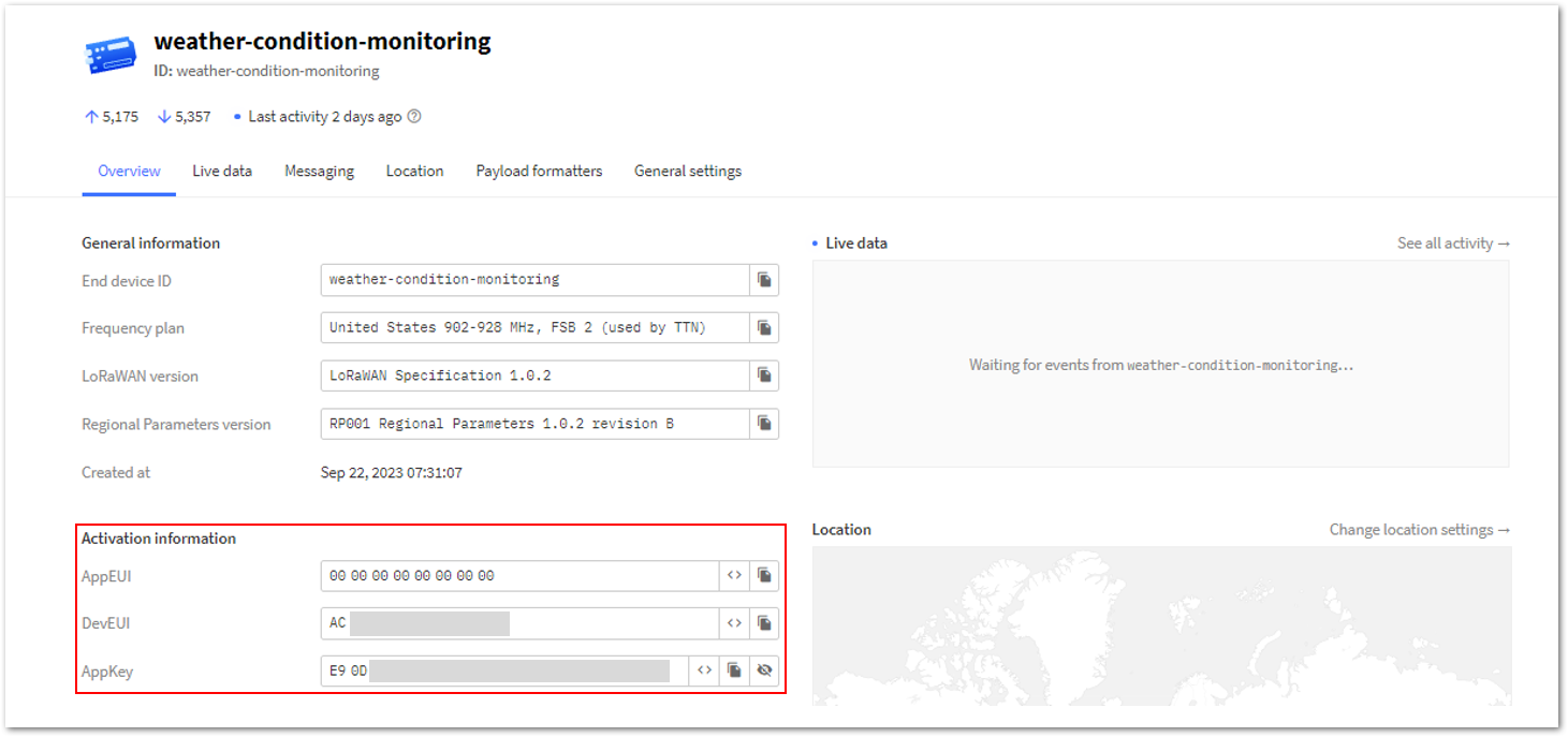 Figure 1: Device's credentials registered in TTN
- Once you're done with the code, proceed with uploading it to your device. Choose your RAK4631 board on your desktop or laptop. To do so, navigate to Tools > Board:XXXXX > RAKwireless nRF Boards and select WisBlock RAK4631.
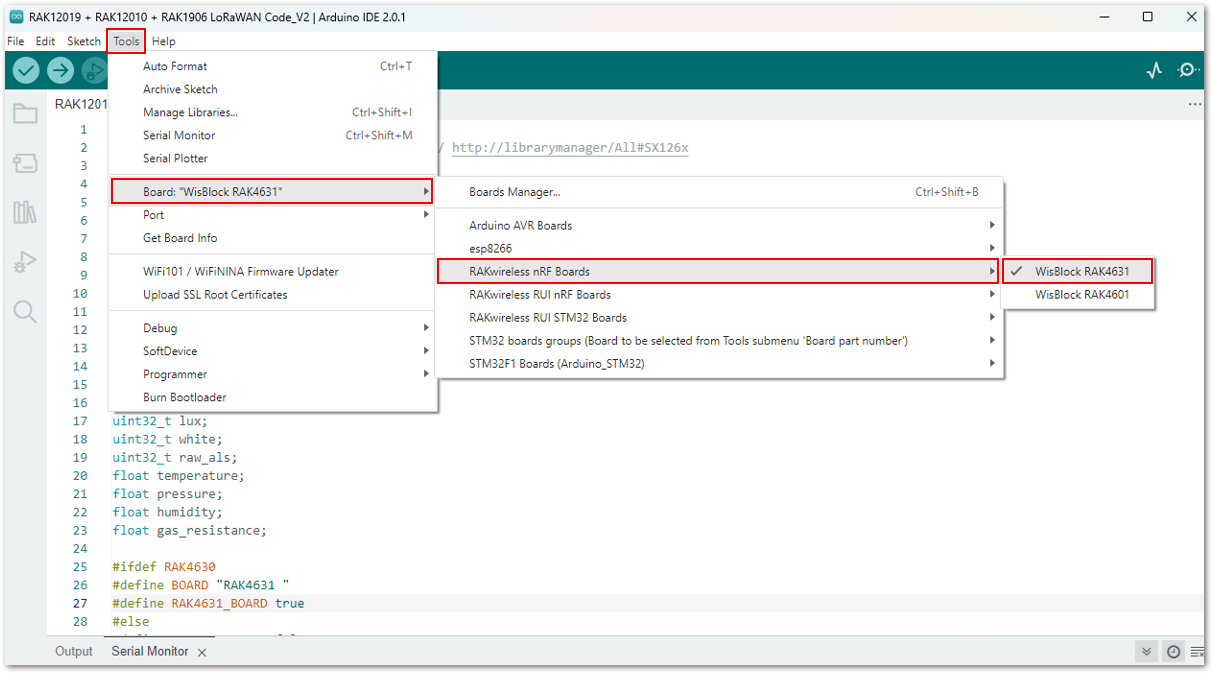 Figure 1: Selecting the RAK4631 board
- After you have selected your board, go to Tools > Port and select the specific port of your board.
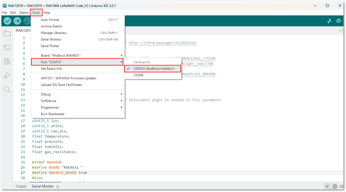 Figure 1: Selecting the port of RAK4631 board
- Upload your code by clicking the Upload button .
Once completed, the Device programmed notification will appear in the console at the bottom of the Arduino IDE.
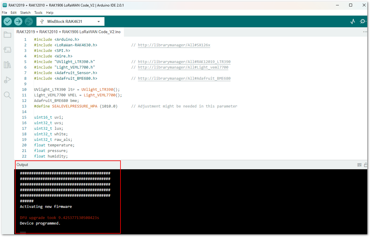 Figure 1: Arduino code is successfully uploaded into your RAK4631 board
Weather Condition Monitoring via TTN
- To monitor the data of your Weather Condition Monitoring device via TTN, go back to the TTN account where you created your application and registered your device.
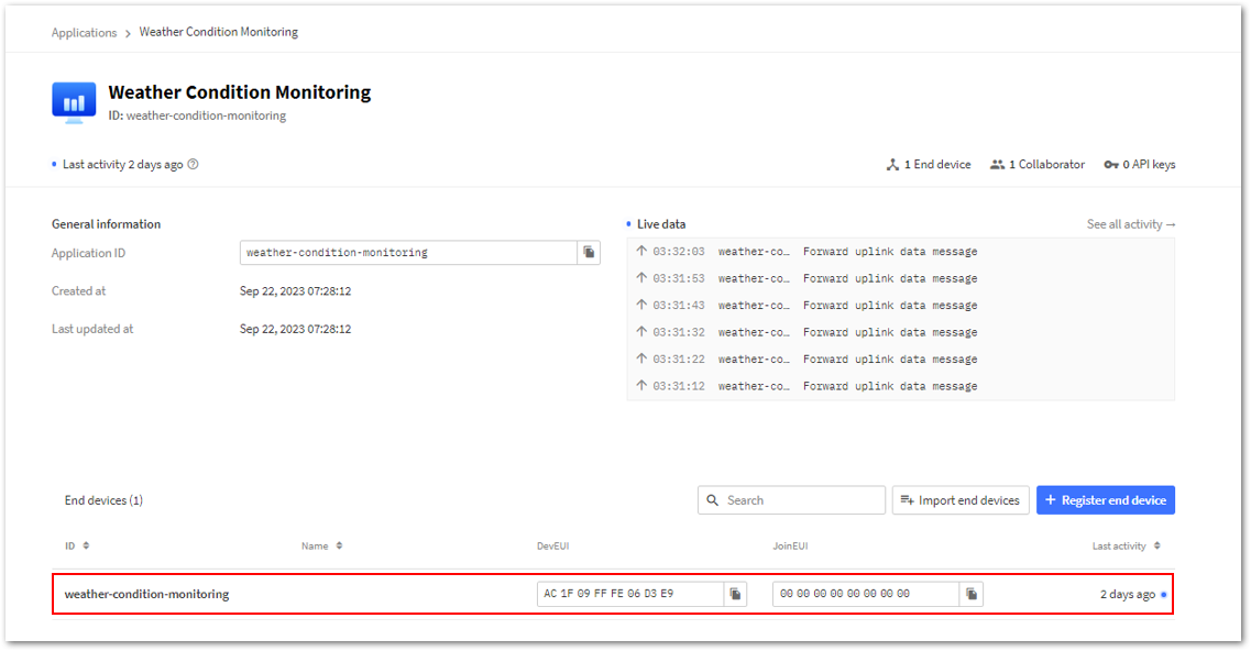 Figure 1: Your Weather Condition Monitoring device in TTN
- Then go to Payload formatters. Under Formatter type, select Custom Javascript formatter.
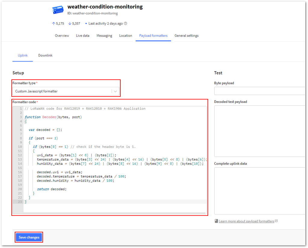 Figure 1: Payload Formatter
- Under the Formatter code, replace the default code with the one below. This will decode the data from your device going to TTN. Once done, simply click Save changes.
// LoRaWAN code for RAK12019 + RAK12010 + RAK1906 Application

function Decoder(bytes, port)
{

  var decoded = {};

  if (port === 2)
  {
    if (bytes[0] == 1) // check if the header byte is 1.
    {
      uvi_data = (bytes[1] << 8) | (bytes[2]);
      temperature_data = (bytes[3] << 24) | (bytes[4] << 16) | (bytes[5] << 8) | (bytes[6]);
      humidity_data = (bytes[7] << 24) | (bytes[8] << 16) | (bytes[9] << 8) | (bytes[10]);

      decoded.uvi = uvi_data;
      decoded.temperature = temperature_data / 100;
      decoded.humidity = humidity_data / 100;

      return decoded;
    }
  }
}
- Go back to Live data of your device in TTN and compare it with the live data from the Serial Monitor of your device.
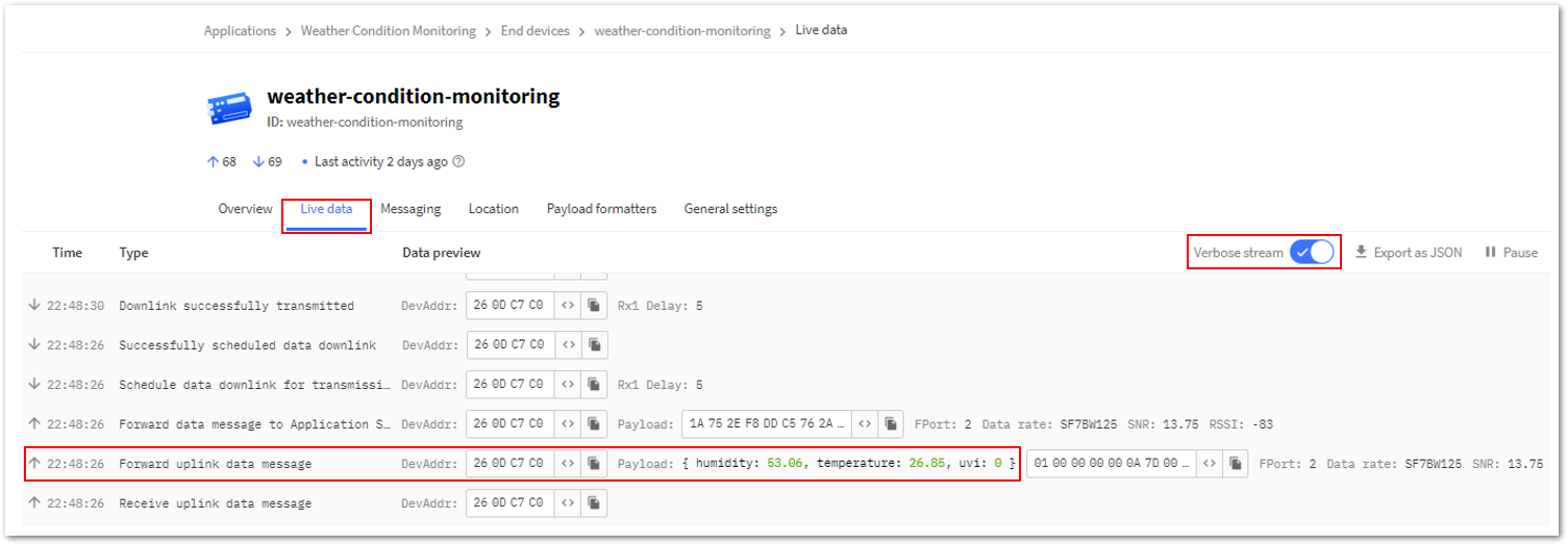 Figure 1: Live data from your device in TTN
You should see identical results between them.
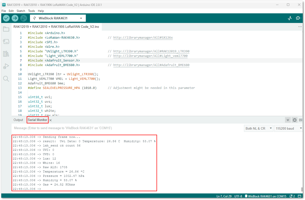 Figure 1: Live data from your device in its Serial Monitor
Weather Condition Monitoring via Akenza Platform
This section will guide you on how to integrate your application using Akenza. Here's the outline of the guide:
- Create an Account and Workplace
- Setup Connectivity Integration
- Add Device connectors
- Create the Device Type
- Create a Dashboard
- Go to Akenza Portal and register to create your account.
Figure 1: Creating Akenza Account- After completing the account registration, log in to your Akenza Account. Configure your setup, and then select Create Workspace.
Figure 1: Create a Workspace- On the pop-up window, provide details such as your workspace Name and its description. Then, click Create Workspace.
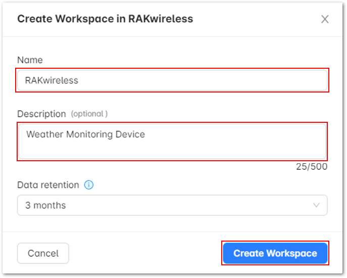 Figure 1: Create a Workspace
- You should be able to see a RAKwireless Workspace successfully created.
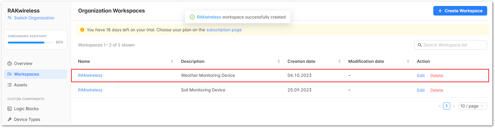 Figure 1: Workspace successfully created
After successfully creating the Workspace, connect it to The Things Stack.
To do so, execute the following steps:
- On the left panel, navigate to Integrations and click Create Integration button.
Figure 1: Create a Integration- It will show the different Connectivity Integration setup. For this guide, choose The Things Stack.
Figure 1: The Things Stack- Setup your first Connectivity Integration by following the steps below:
- Under TTN LoRaWAN host of Integration login, choose the appropriate community to which you belong.
Figure 1: TTN LoRaWAN host- In the Authentication field, select Application ID / API Key in the drop-down menu.
Figure 1: Authentication- For the Application ID, copy the TTN Application ID and paste it to your Akenza workspace.
a. Navigate to your TTN Applications, and select Weather Condition Monitoring
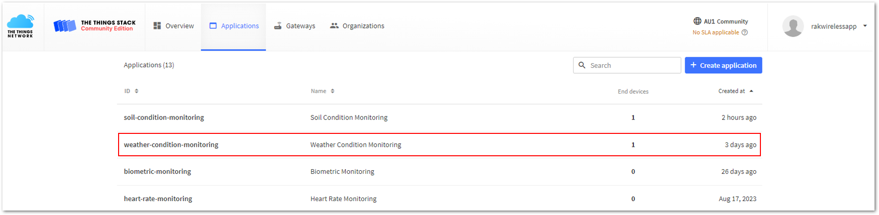 Figure 1: Applications in TTN
b. In the Overview page, copy the Application ID.
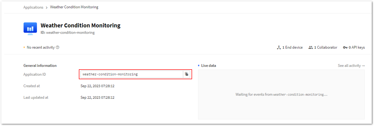 Figure 1: Copying the Application ID of your application in TTN
c. Paste the copied application ID into your Akenza workspace Application ID field.
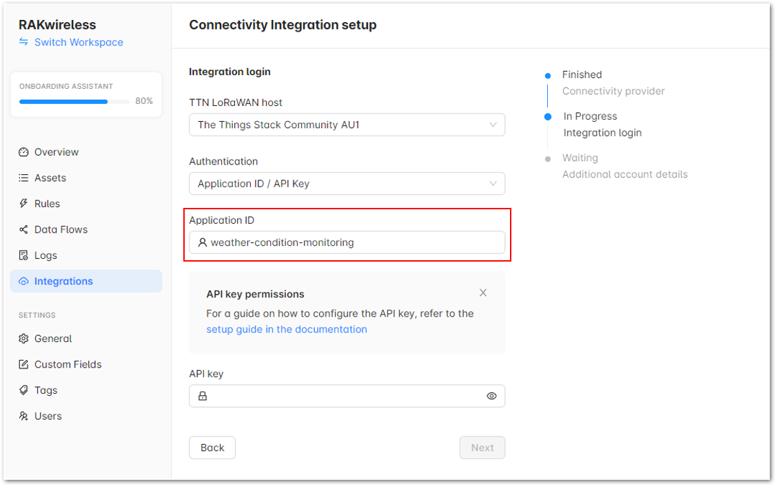 Figure 1: Pasting the Application ID in your Akenza workspace
- Finally, for the API keys, follow the steps below:
a. Go back to your TTN Applications, and select Weather Condition Monitoring.
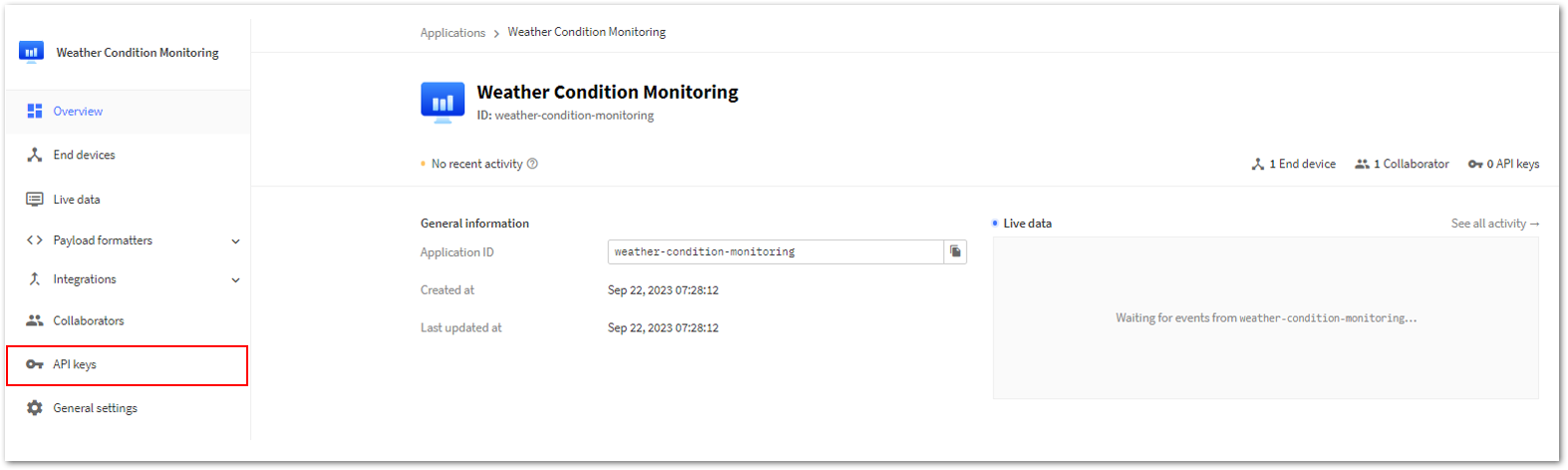 Figure 1: API keys
b. In the left panel, click API keys, then click on the Add API key button.
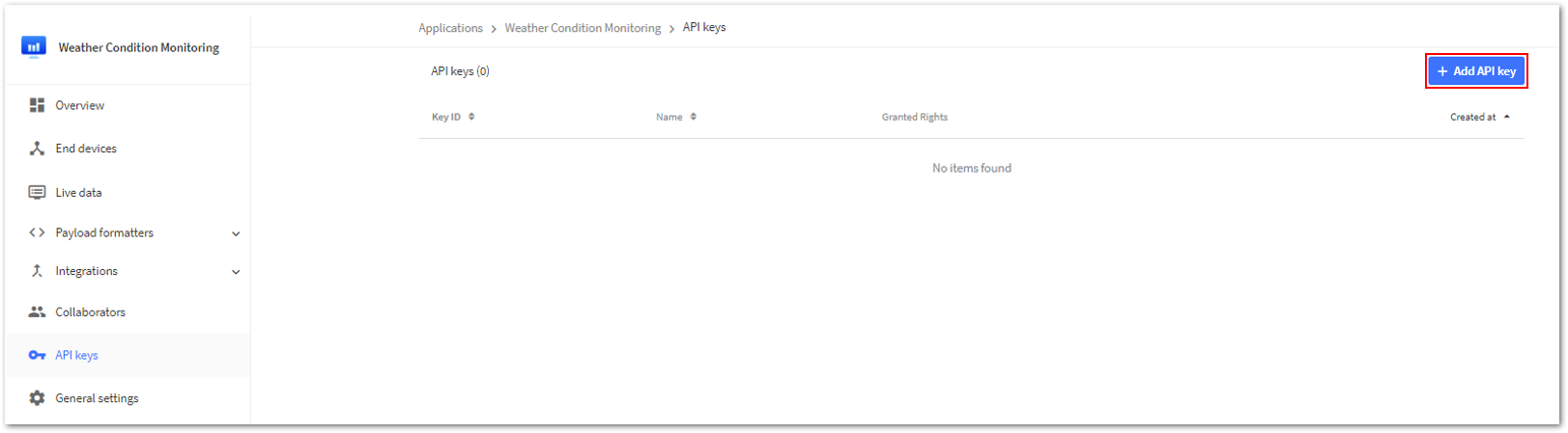 Figure 1: Add API key
c. Enter the Name, select the Rights, and click Create API key.
Figure 1: API key creationd. Once done, copy the created API key and click on the I have copied the key button.
Figure 1: Created API keye. Paste the API key from the TTN application to the API key field of your Akenza workspace. Then, click Next to proceed.
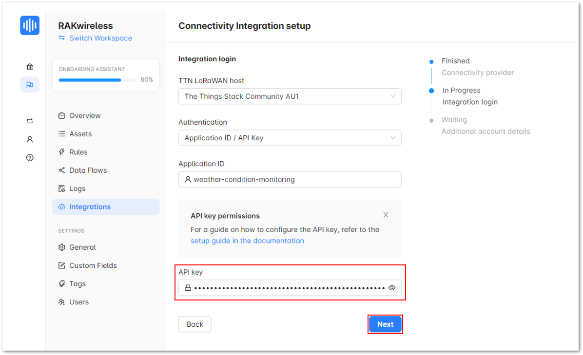 Figure 1: Akenza - API key
f. Under Additional account details, enter details in the Integration name field and then click Next.
Figure 1: Integration nameg. Once done with the integration setup, click Done.
Figure 1: Successful Integration setuph. After clicking Done your window should look like Figure 107.
Figure 1: Successful Integration setupi. Go back to your application in TTN and go to Integrations. You should now see the created API key.
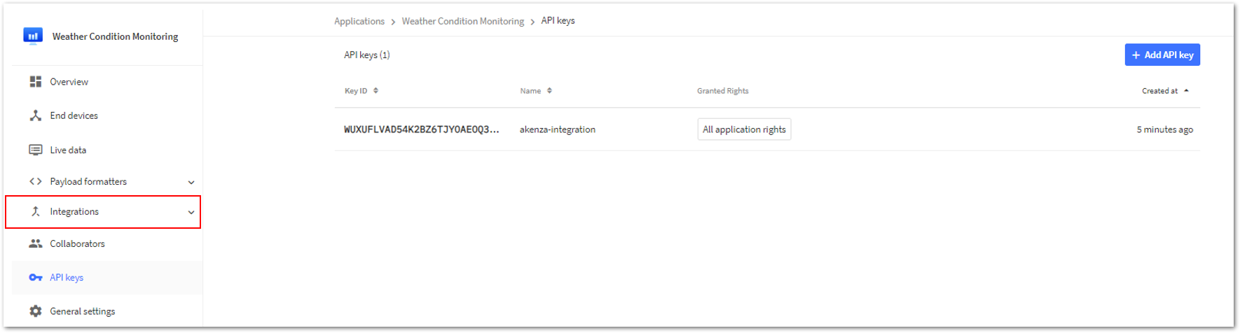 Figure 1: Integrations
j. After a successful Integration, expand the Integrations drop-down, and select Webhooks. You will notice that a webhook is already generated.
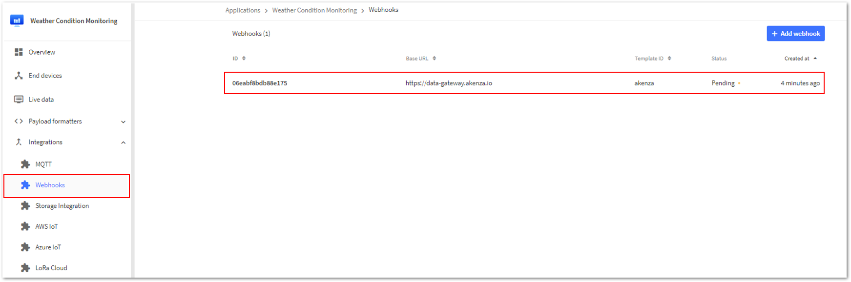 Figure 1: Webhooks
k. Go back to your Akenza workspace and click on Assets. Then, click on your device integrated with Akenza.
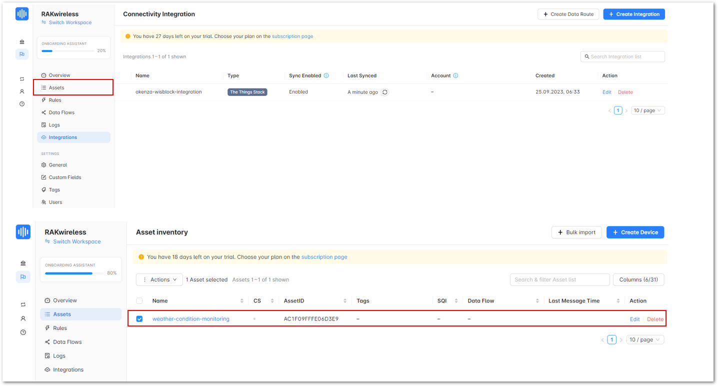 Figure 1: Your device integrated with Akenza
- Create a New Data Flow
- On the left panel, navigate to Data Flows and click the Create Data Flow button.
Figure 1: Create a Data Flow- After that, click on Create new Data Flow.
Figure 1: Create a new Data Flow- Select and configure device connectivity.
- Click on Device Connector
Figure 1: Device Connector- It will show the various Device connectors. Choose LoRa for this guide.
Figure 1: LoRa under Device connector- After choosing LoRa, a list of LoRa Device connectors will appear. Choose The Things Stack.
Figure 1: The Things Stack- Then, click TTN Connector - akenza-wisblock-integration.
Figure 1: TTN Connector - akenza-wisblock-integration- Configure the device data destinations.
- Click Add Output Connector.
Figure 1: Add Output Connector- Under Database, choose Akenza DB for this guide.
Figure 1: akenza DB- Output connector is successfully added. Click Save Data Flow.
Figure 1: Save Data Flow- Enter the Name on the popup window, then click Save Data Flow.
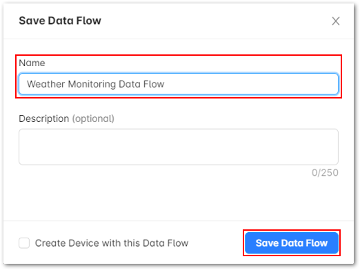 Figure 1: Save Data Flow
- Set the Data Overview
- Go back to Assets.
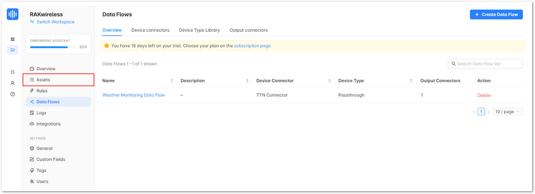 Figure 1: Assets
- Then highlight your device integrated with Akenza.
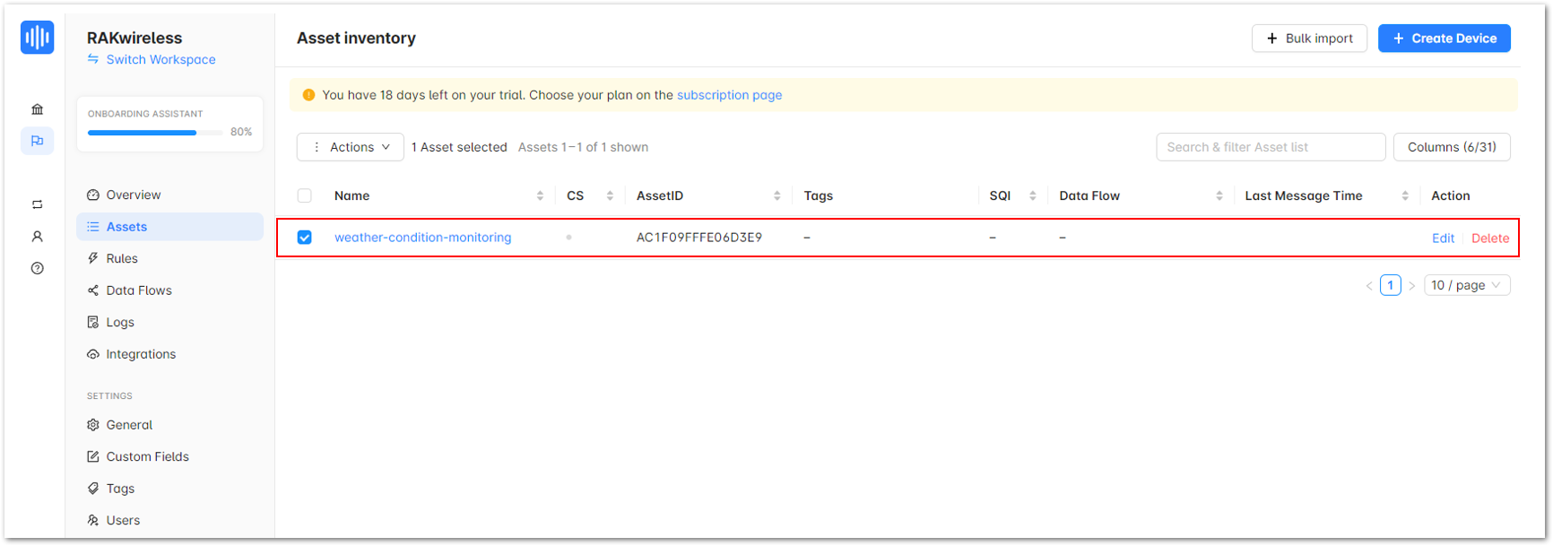 Figure 1: Your device integrated with Akenza
- Click on the drop down More, then choose Edit.
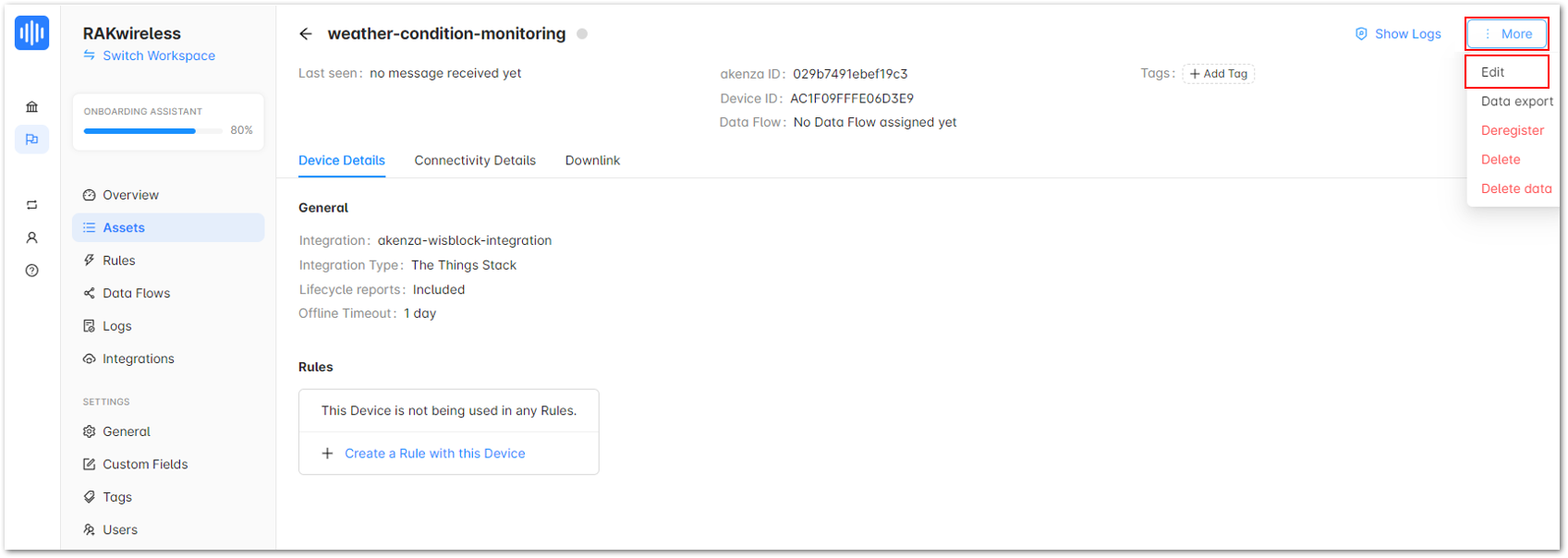 Figure 1: Your device integrated with Akenza
- Under Data Processing, click on Data Flow.
Figure 1: Data Flow- Then select the Data Flow of your device.
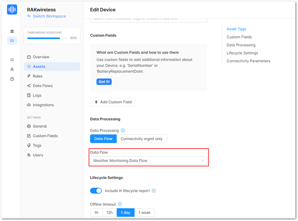 Figure 1: Data Flow
- Once done, click Update Device.
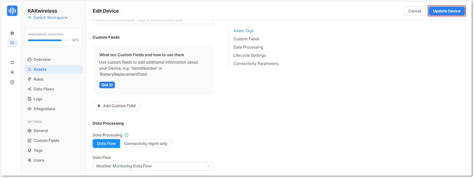 Figure 1: Update Device
- You should now be looking at the data overview of your device integrated with Akenza.
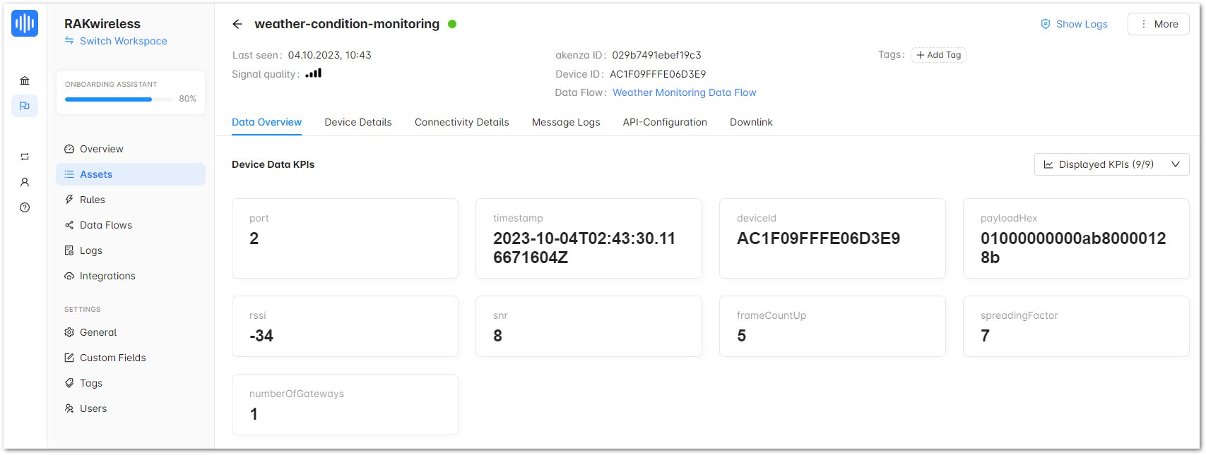 Figure 1: Data Overview
Device Types extract, transform and normalize the data sent from the device. These are the steps on how to add a Device Type:
- Go to Device Types then click Create Device Type.
Figure 1: Create a Device Type- Once done, provide details under Device type name, then click Next.
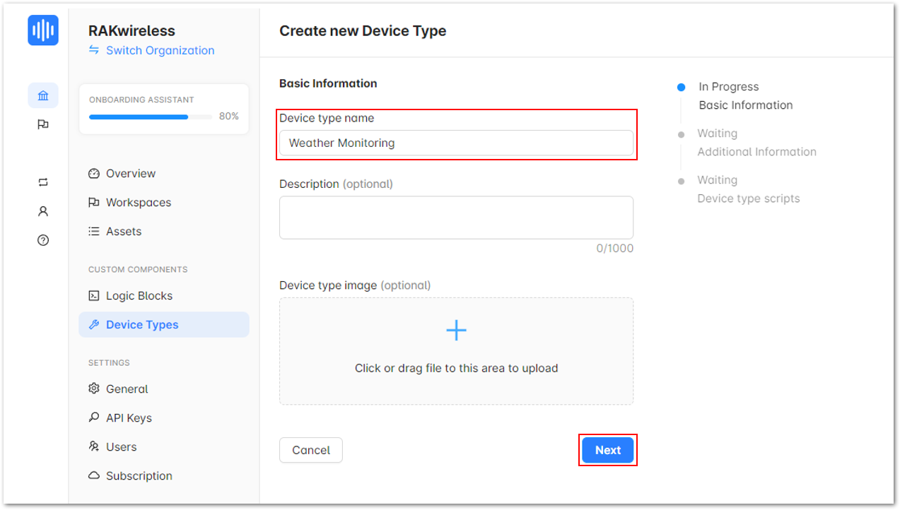 Figure 1: Device type name
- On the next portion, click Next.
Figure 1: Other information of your device- After that, click on Open script editor.
Figure 1: Open script editor- Provide the decoder for your device.
Figure 1: Uplink script- Then into the Uplink script, replace the default script with the code below:
function consume(event)
{
    const payload = event.data.payloadHex;
    const port = Number(event.data.port);
    const bytes = Hex.hexToBytes(payload);

    const decoded = Decoder(bytes, port);

    emit('sample', { data: decoded, topic: "default" });
}
- Go back to your application in TTN and copy the decoder in the Payload formatters.
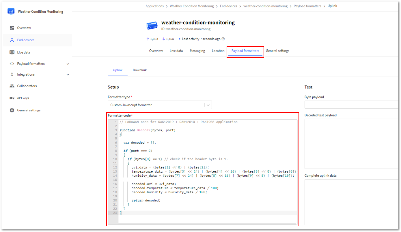 Figure 1: Decoder of your Weather Monitoring device in TTN
- Go back to Akenza and paste it on the next lines of the Uplink script.
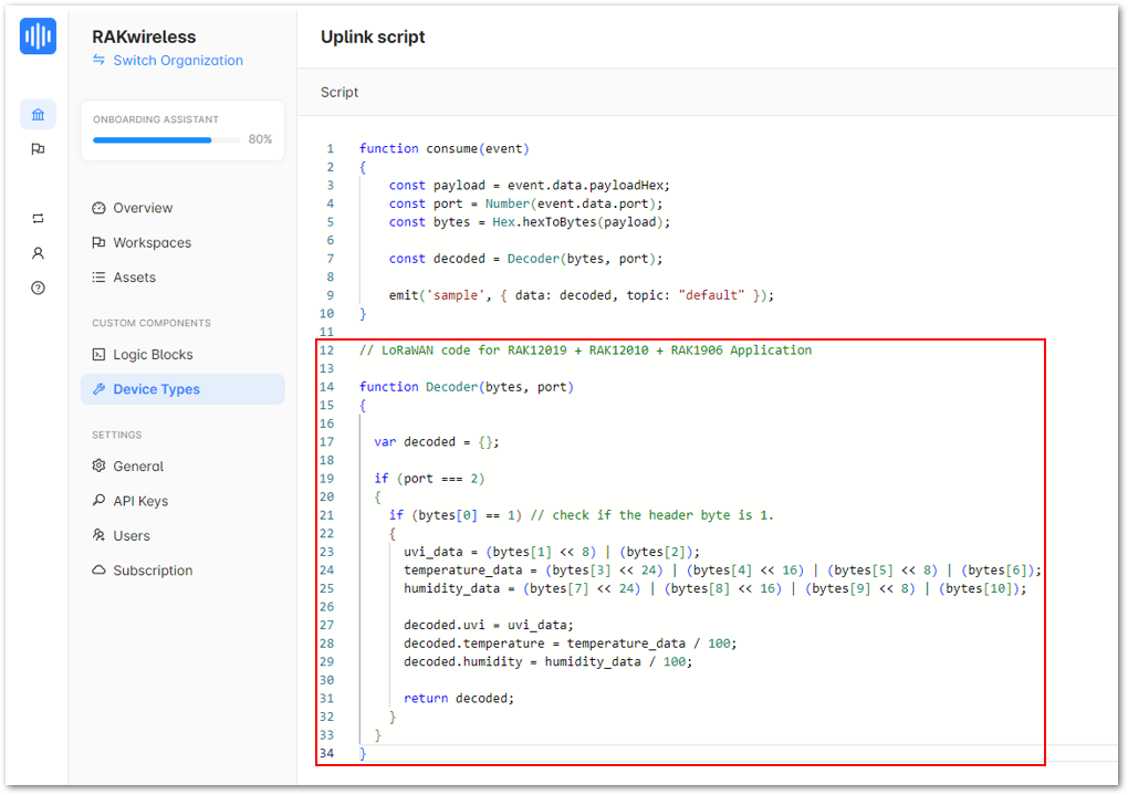 Figure 1: Uplink script
- Then insert the word "let" at the beginning of every variable and rearrange the code in the sequence shown in Figure 136. Finally, click on Save.
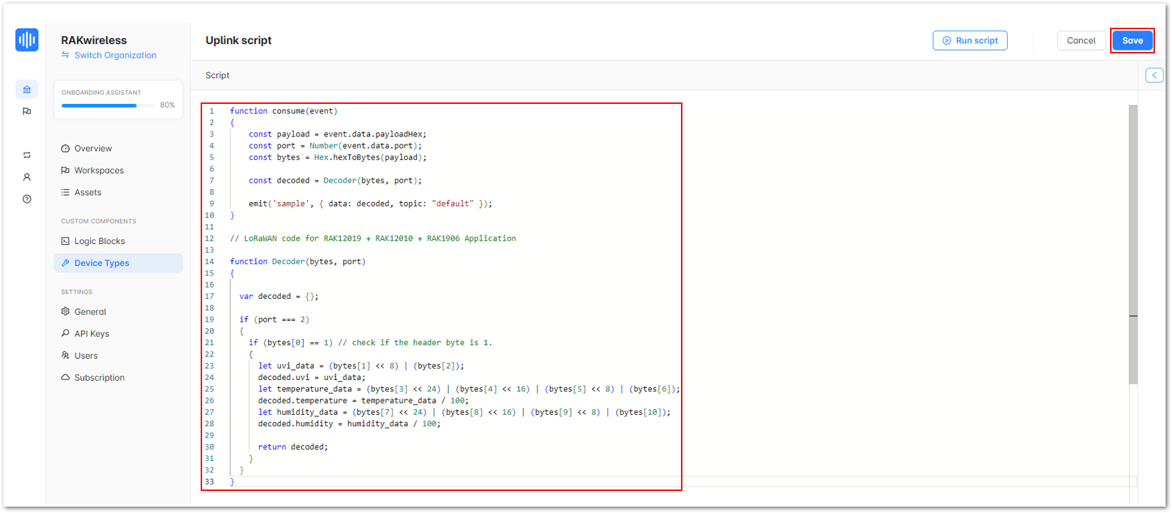 Figure 1: Modified script
- Once done, go to Data Flows and click on your device's data flow.
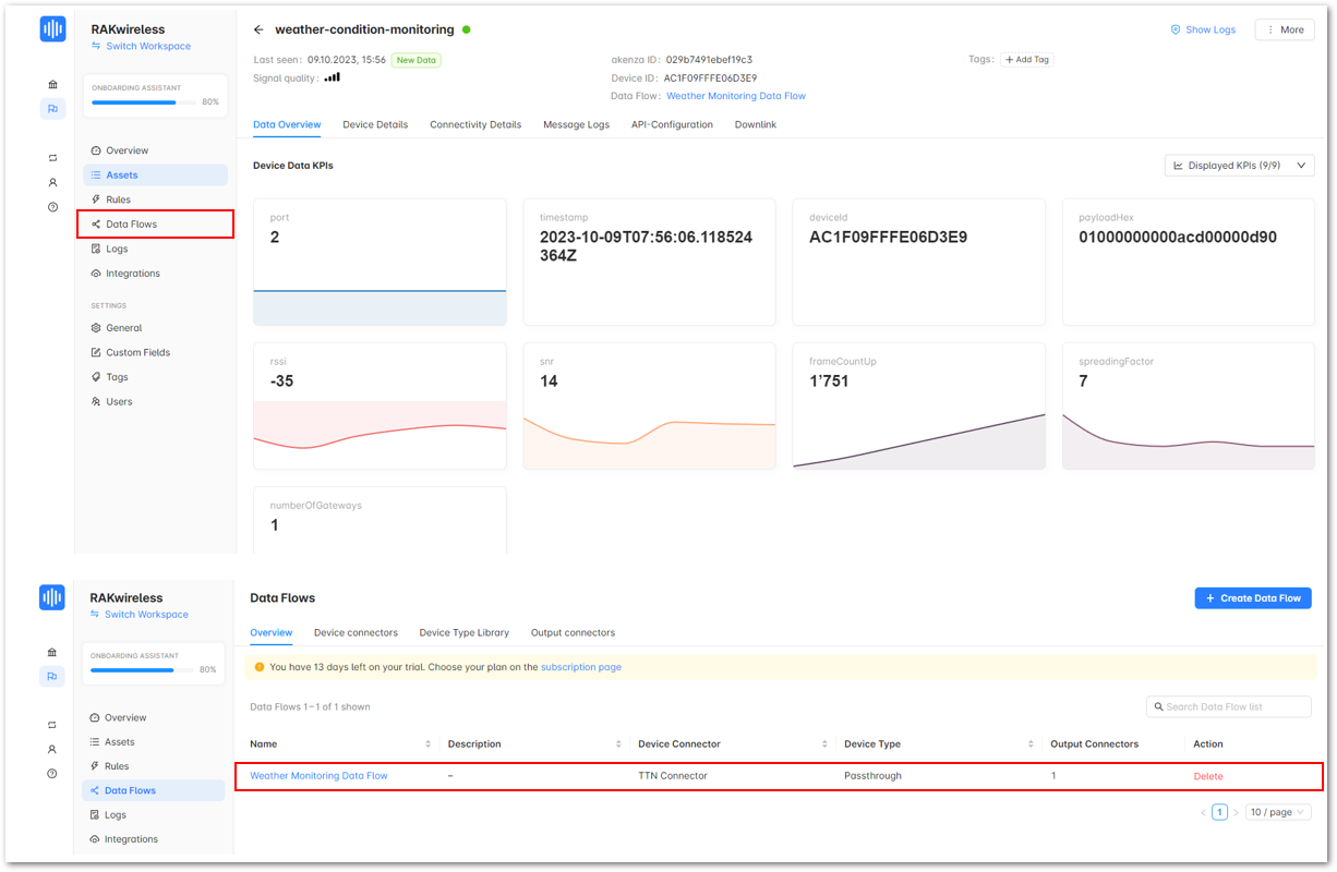 Figure 1: Your device's data flow
- Click Add Device Type, then select your custom device.
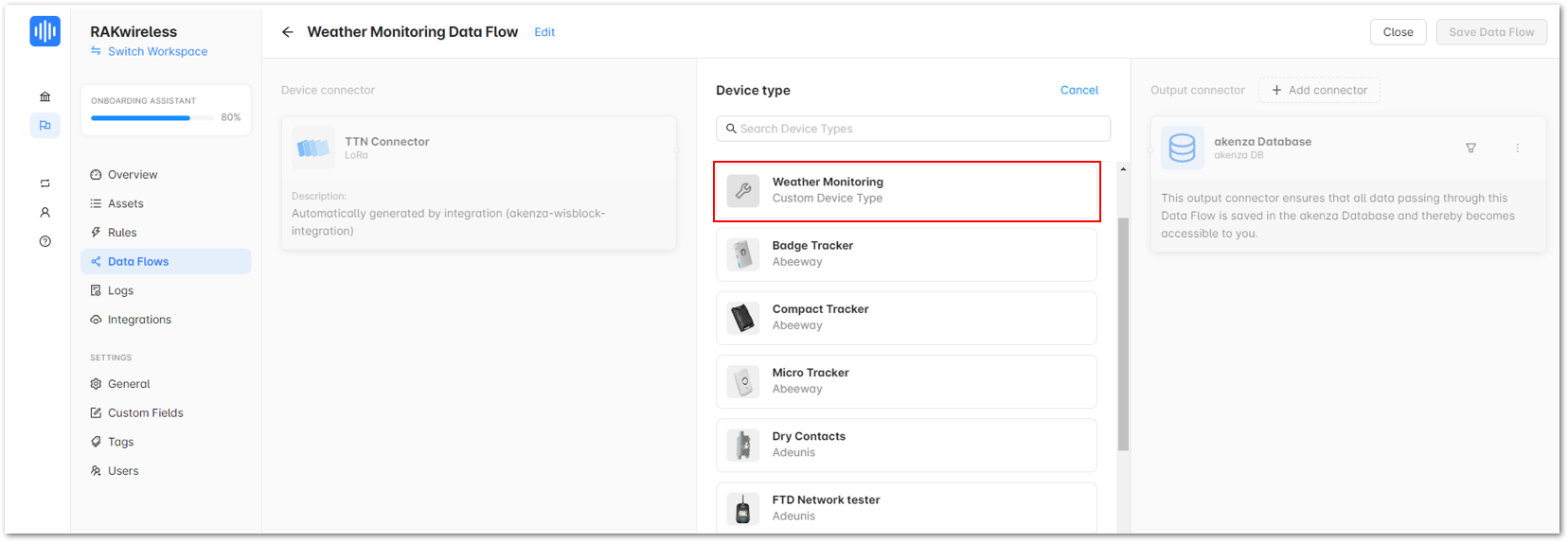 Figure 1: Weather Monitoring device
- Once done, click Save Data Flow.
Figure 1: Save Data Flow- Go to Assets and click on your device.
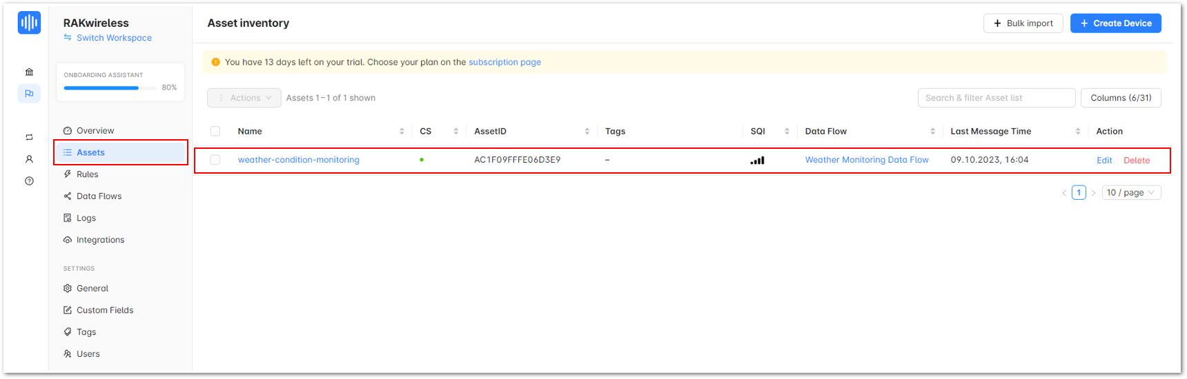 Figure 1: Assets
- You should now see a working Soil Monitoring workspace in Akenza showing the data from your Soil Monitoring device.
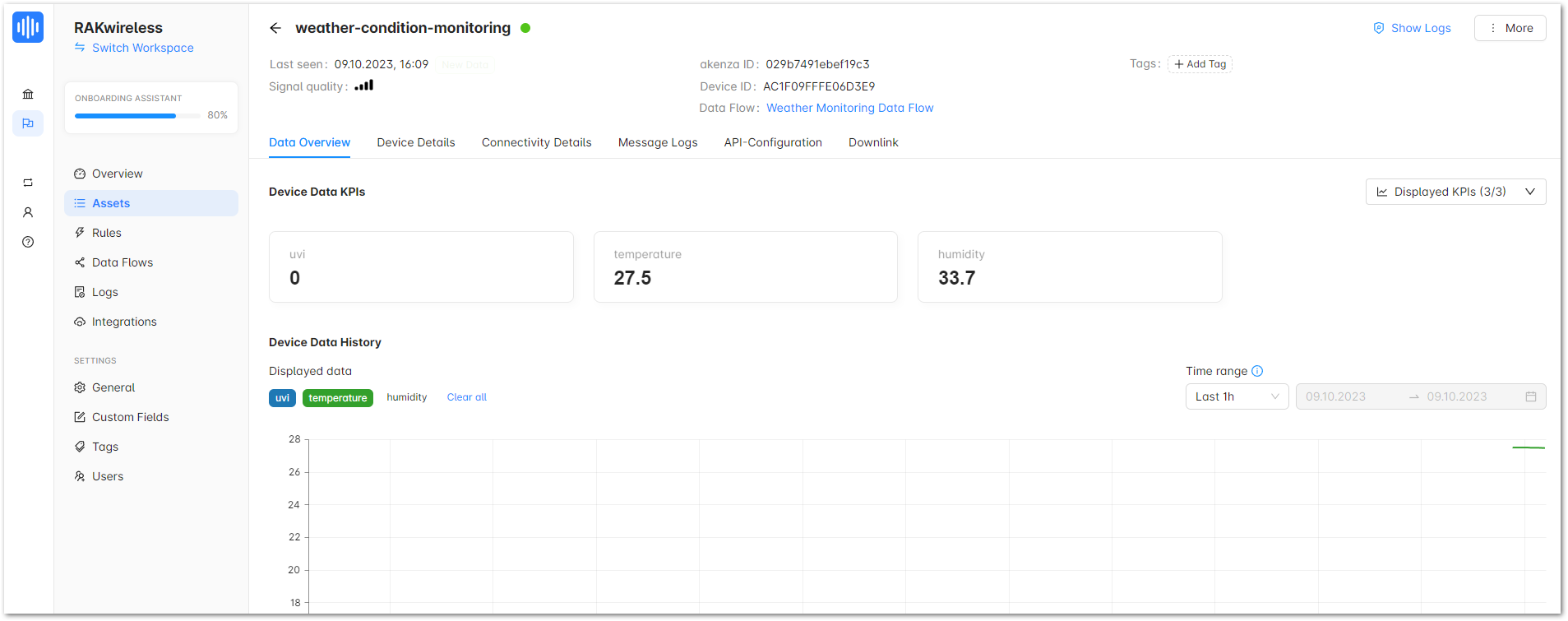 Figure 1: Your device's data overview
The dashboard builder makes it easy to create custom dashboards and display data stored in Akenza. These are the steps on how to create a working dashboard for your Weather Monitoring device:
- Access Dashboard module a. Click on Home then go to Device Management > Dashboard Builder.
Figure 1: Dashboard Builderb. Click Create a Dashboard.
Figure 1: Create a Dashboard- Configure Dashboard Settings
a. Enter the desired Name for your application and click Next.
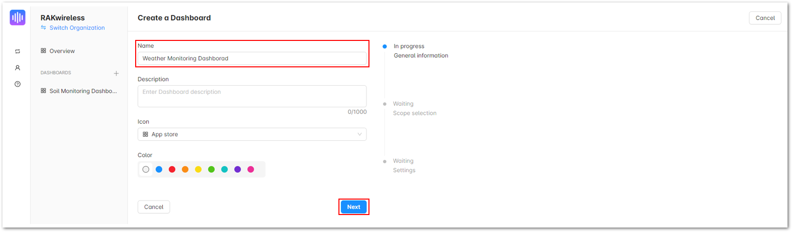 Figure 1: Create a Dashboard
b. Select the specific workspace of your application. Click Next.
Figure 1: Create a Dashboardc. Under Refresh interval, choose 1 min to load the latest data for every 1 minute, then click Create a Dashboard.
Figure 1: Create a Dashboard- Add Components
a. Once you created your dashboard, click the Add Component dropdown menu and choose Chart.
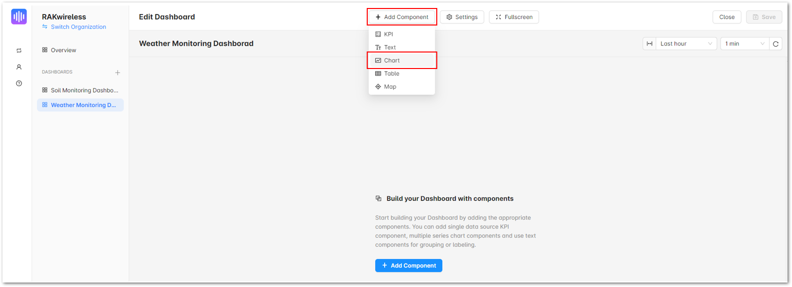 Figure 1: Weather Monitoring Dashboard
b. Under the Content tab, on the Heading field, input the details of the parameter you will monitor.
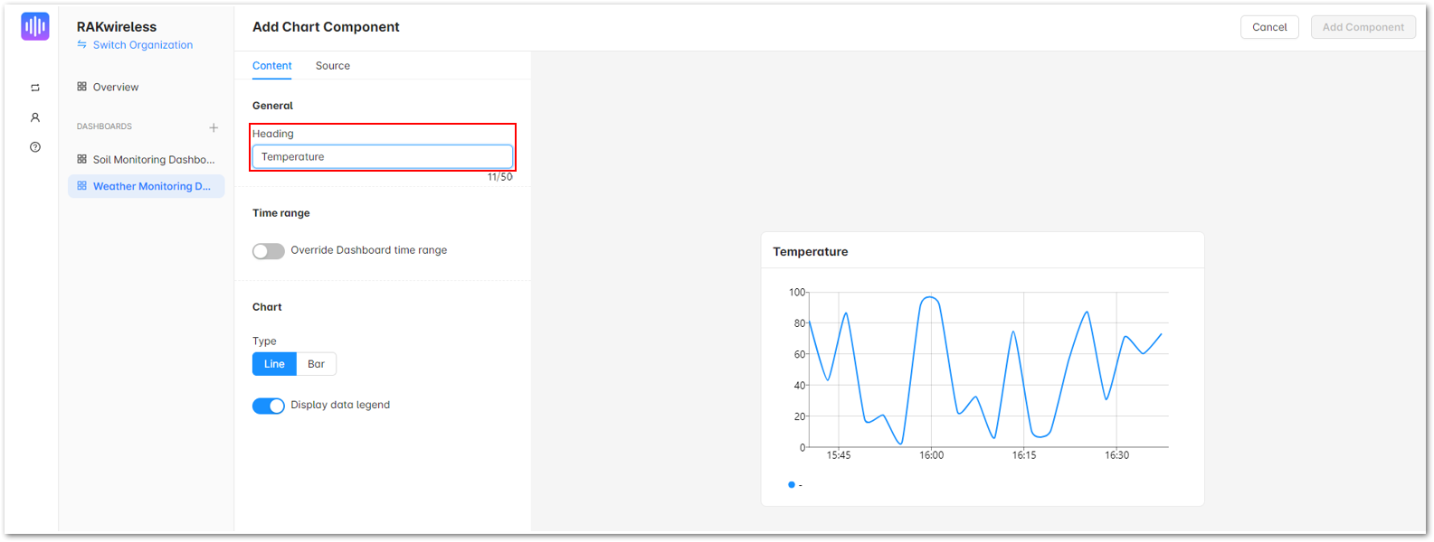 Figure 1: Chart Component
c. After that, click on the Source tab. Select your Weather Monitoring device on the Device field.
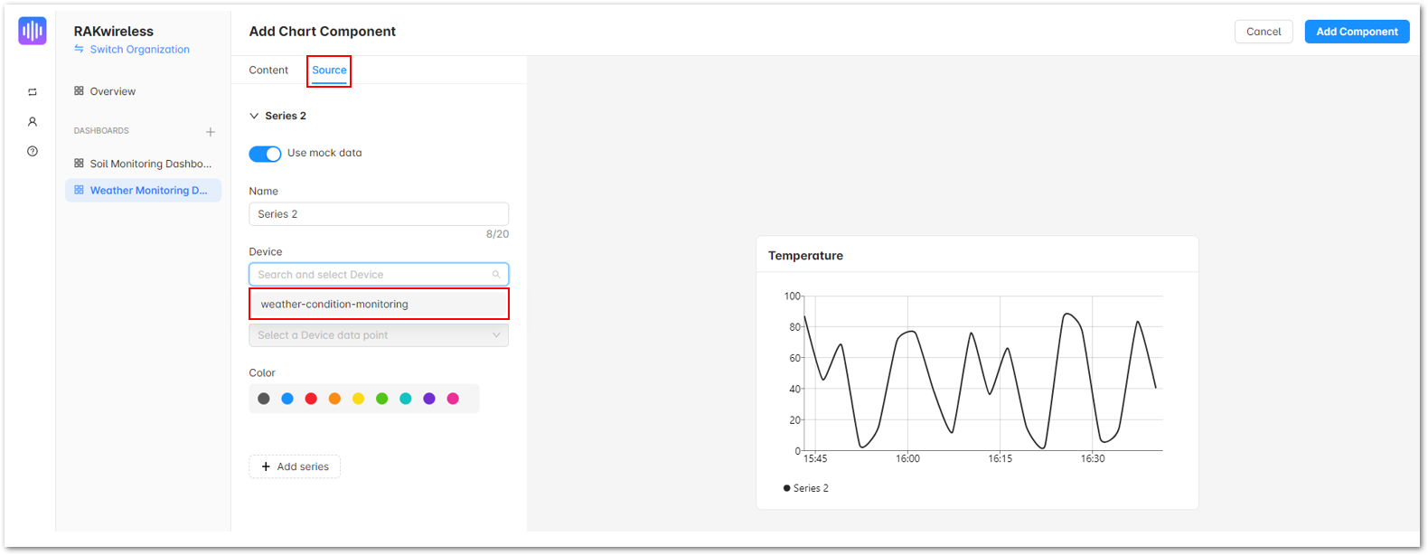 Figure 1: Chart Component
d. Move to Data Point field, then select Default and the specific parameter for your chart.
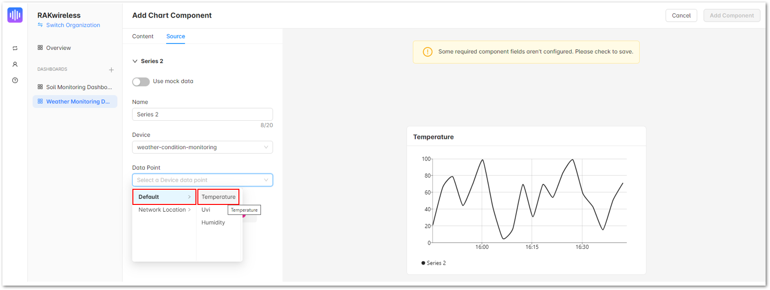 Figure 1: Chart Component
e. Once done, click Add Component.
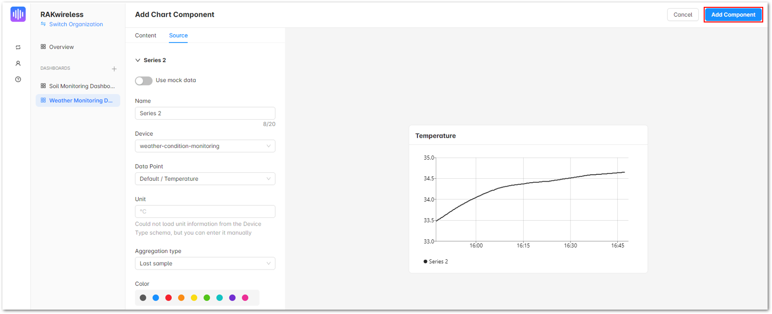 Figure 1: Chart Component
- To add charts for other parameters to be included in the dashboard, simply repeat Step 3. When you're finished, click Save.
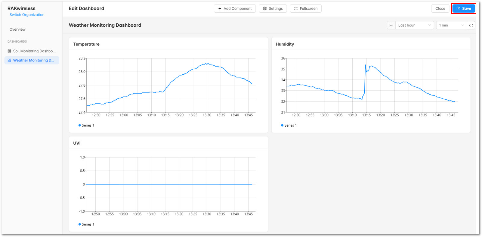 Figure 1: Saving your ashboard
- You should be able to see a working dashboard for your Weather Monitoring device.
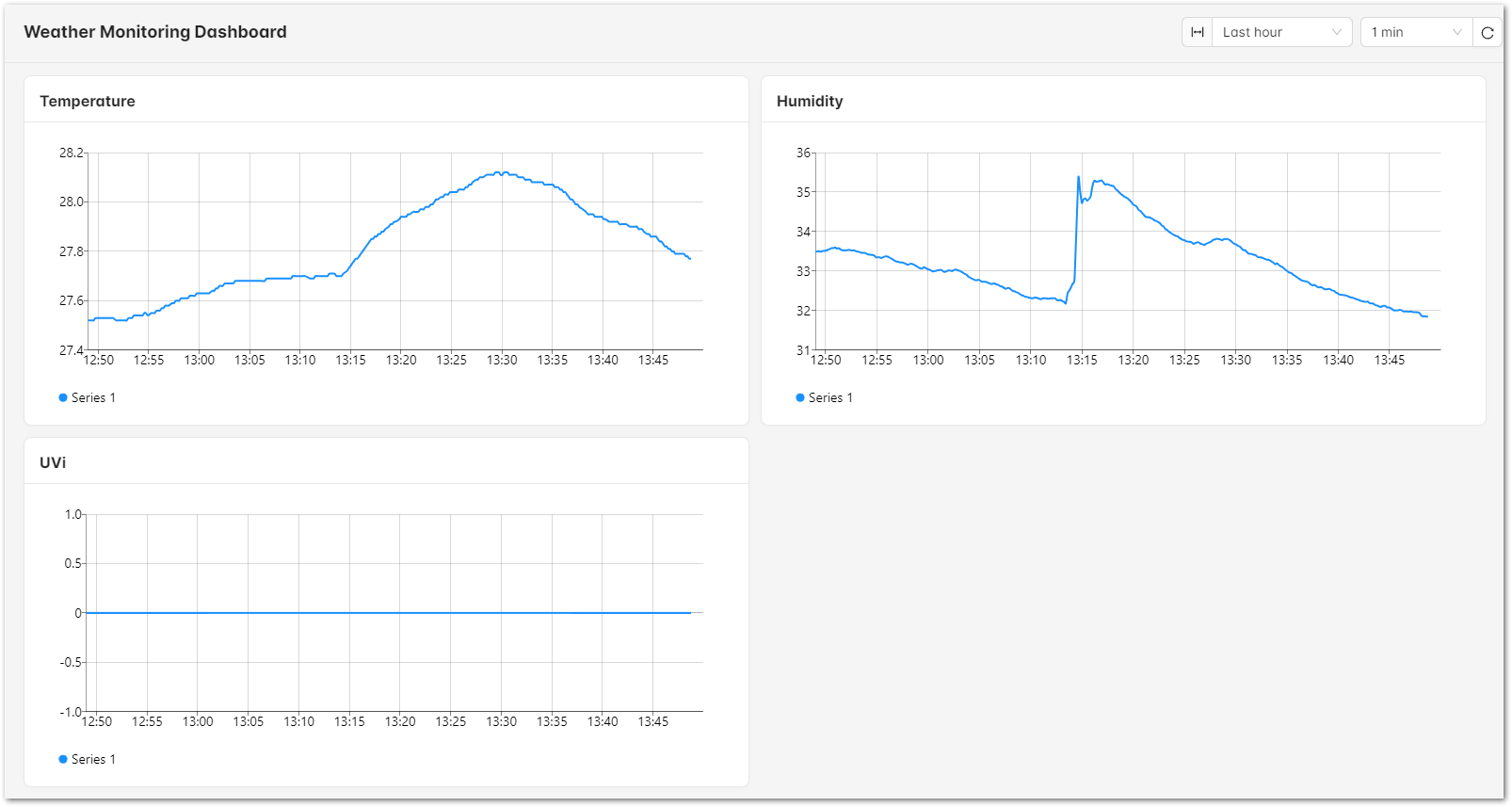 Figure 1: Weather Monitoring Dashboard
Miscellaneous
The Things Network Configuration
Create a TTN Account
- Go to The Things Network and sign up an account.
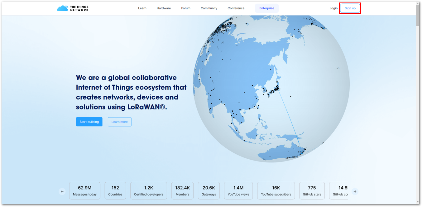 Figure 1: Signing up an account in TTN
- Choose a Community and get started.
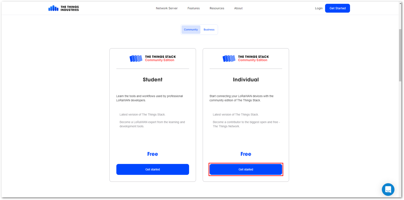 Figure 1: Signing up an account in TTN
- Choose a network cluster.
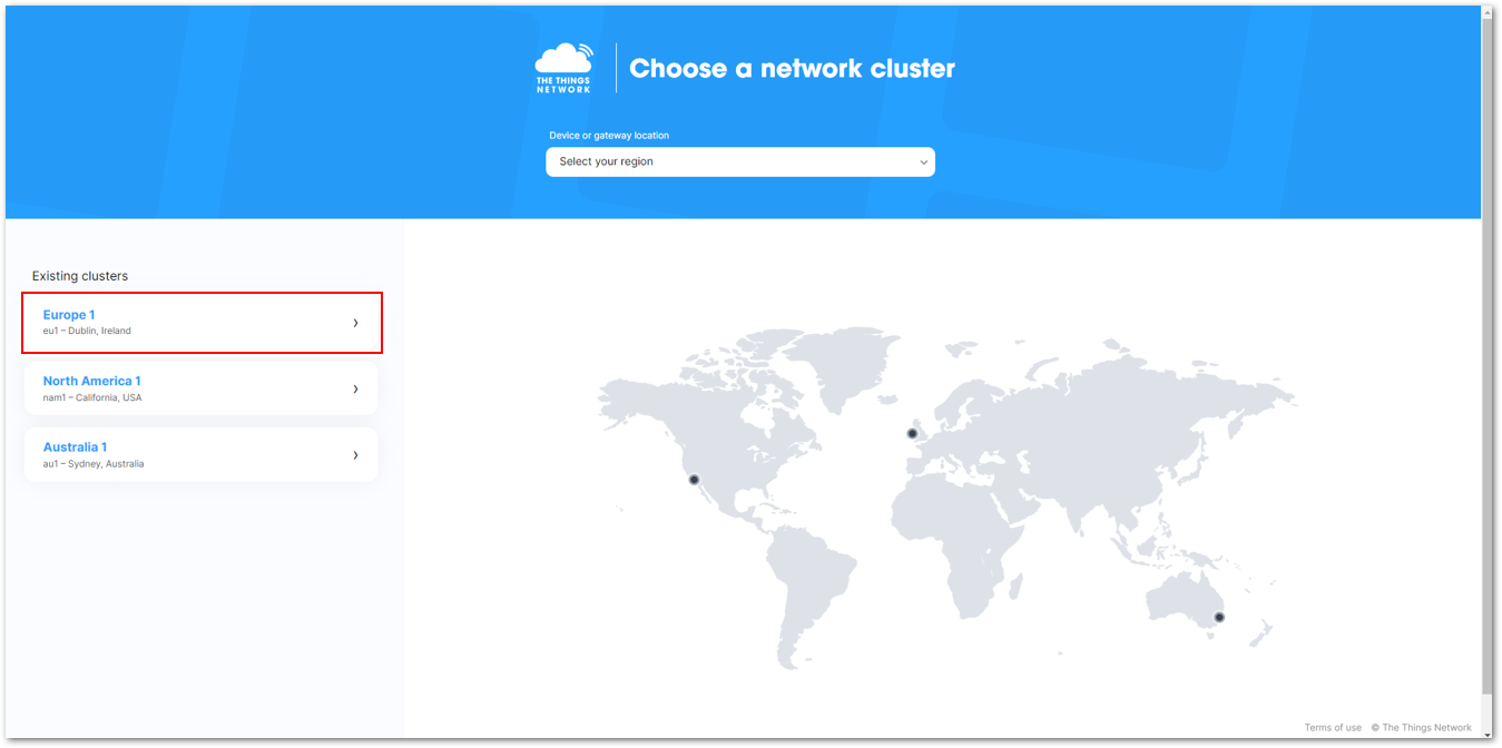 Figure 1: Selecting Cluster in TTN
You can also opt to sign up and create an account using your The Things ID.
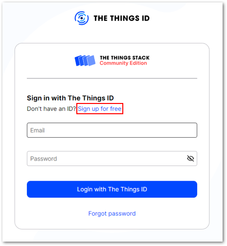 Figure 1: Signing up through the Things ID
If you have a TTN V2, you can use the same login credentials. If you do not yet have an account, you must create one.
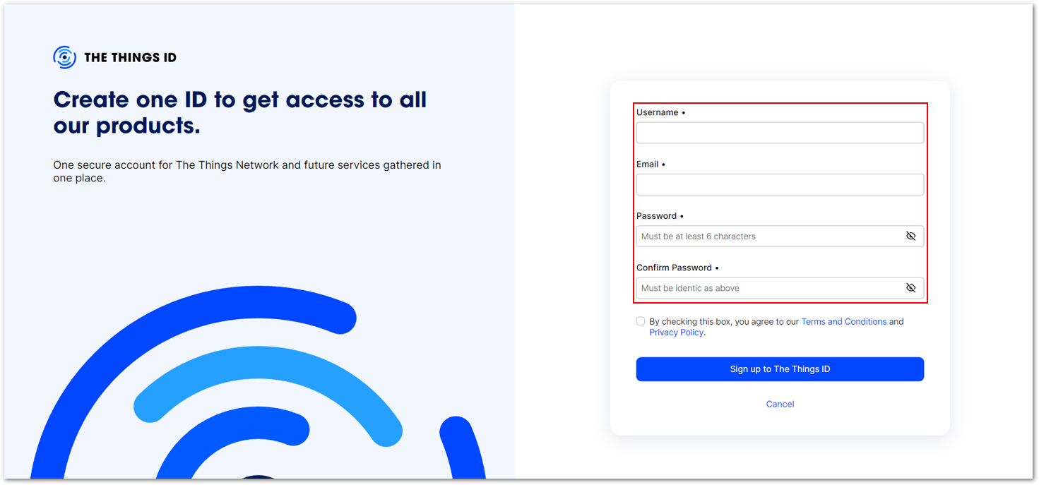 Figure 1: Creation of an account through the Things ID
Adding an Account
- Now that you are logged in to the platform, the next step is to create an application. Select Create an application.
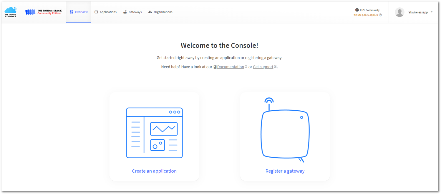 Figure 1: The Things Stack Platform
-
Fill in the needed information, then click the Create application button.
- Application ID: This will be the unique ID of your application in the network. The ID must contain only lowercase letters, numbers, and dashes (-).
- Application name (optional): This is the name of your application.
- Description (optional): Description of your application. Optional application description; can also be used to save notes about the application.
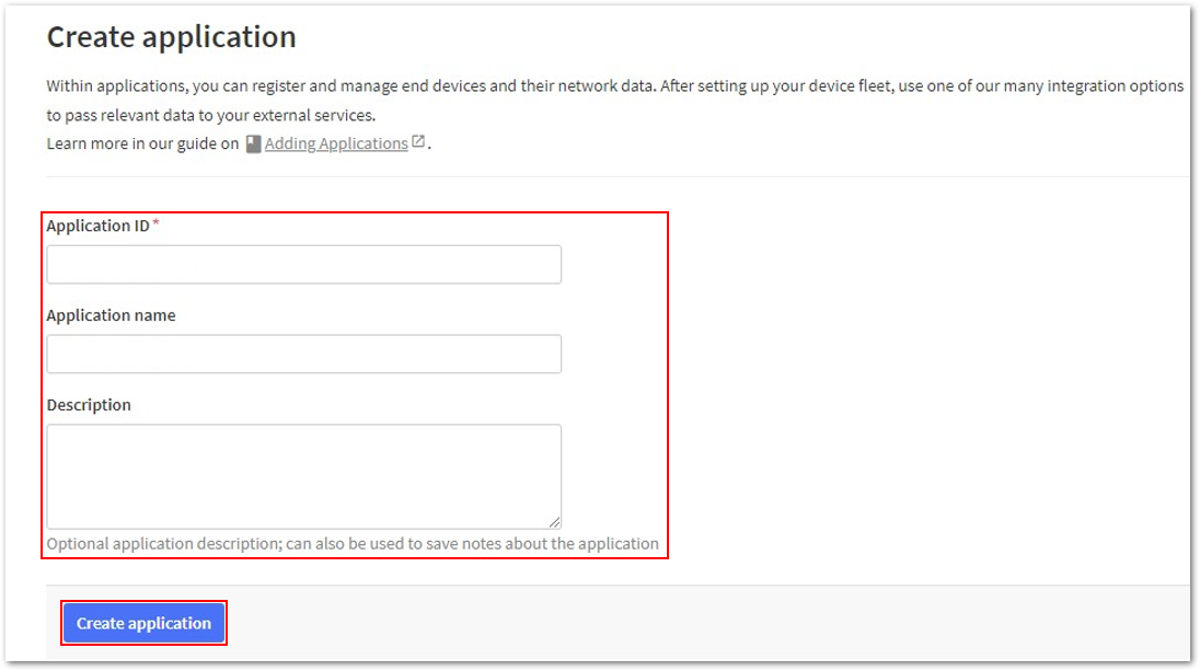 Figure 1: Details of the TTN application
The details and information depend on the device you are using (e.g., RAK12019, etc.).
- If you have no error on the previous step, you should now be on the application console page.
The procedures above are applicable to all applications you will be using. Once done with the TTN account creation, you can visit these following links:
OTAA Device Registration
- To start adding an OTAA end-device, go to your application console and click Register end device.
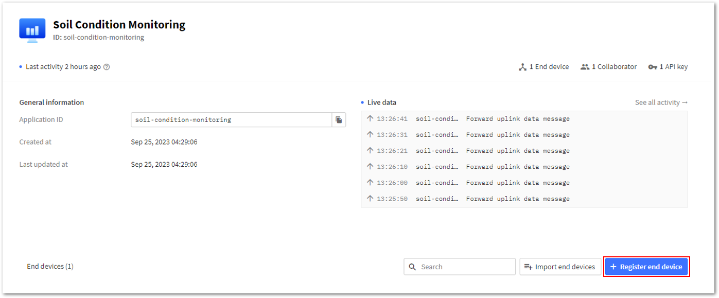 Figure 1: Register End Device
- In the input method, select Enter end device specifics manually to register your device.
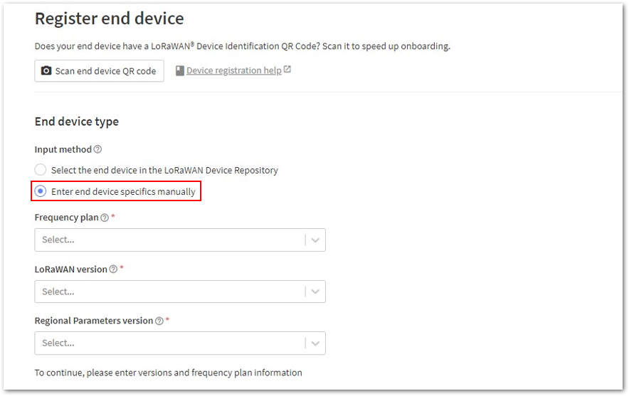 Figure 1: Enter end device specifics manually
- Next, set up the Frequency plan, the compatible LoRaWAN version, and the supported Regional Parameters version. Then provide the JoinEUI credentials by entering zeroes.
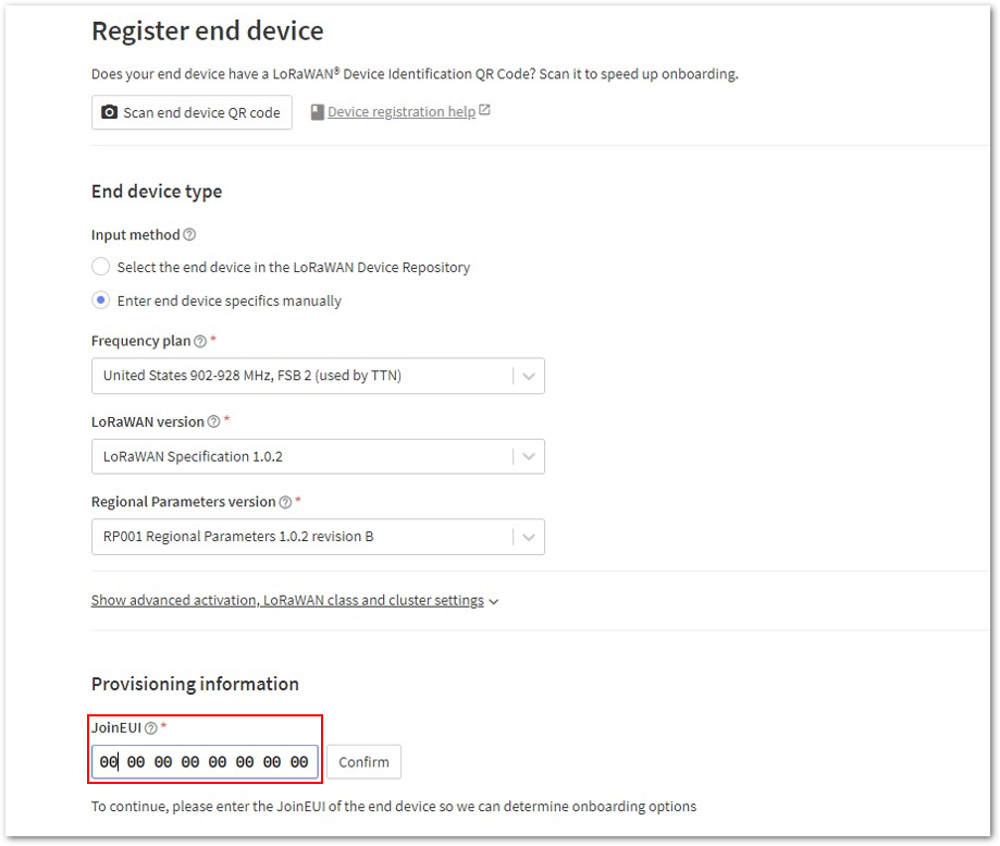 Figure 1: Setting up your device
- Click Show advanced activation, LoRaWAN class and cluster settings.
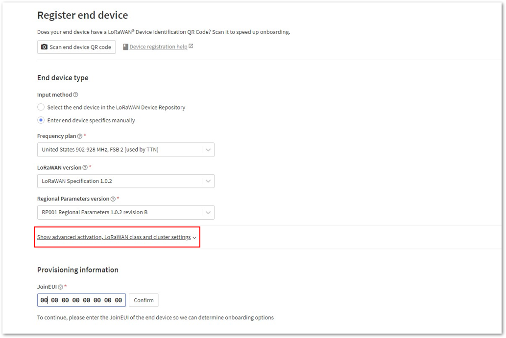 Figure 1: Setting up your device
Then configure the following parameters, then click Confirm:
- Activation mode: Over the air activation (OTAA)
- Additional LoRaWAN class capabilities: None (class A only)
- Network defaults: Use network's default MAC settings
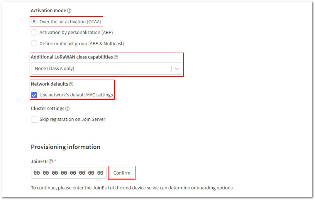 Figure 1: Setting up your device
- Once done, provide the DevEUI credentials of your device into the DevEUI portion.
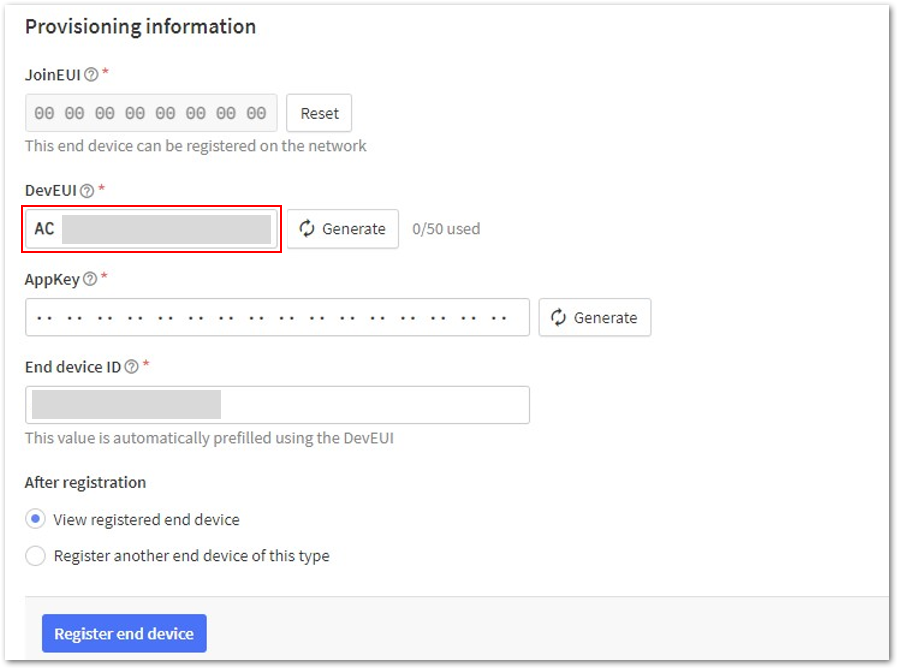 Figure 1: Setting up your device
Click the Generate button under Provisioning Information > AppKey to automatically generate the specific end-device ID of your board.
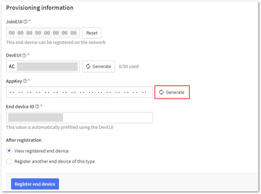 Figure 1: Setting up your device
Once done, you need to change the End device ID since it is automatically prefilled using the DevEUI of your device.
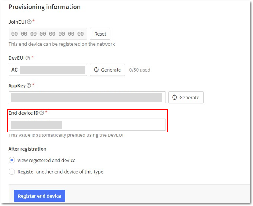 Figure 1: Changing the End device ID
Then click Register end device.
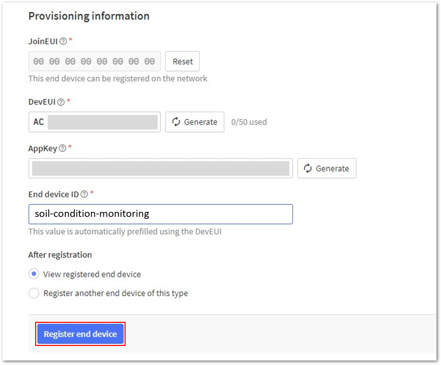 Figure 1: Register End Device
- The AppEUI, DevEUI, and AppKey are hidden in this section as these are unique from a specific device. The DevEUI credential is unique to every RAK4631 device. Also, you should generate your own AppEUI and AppKey credentials for your specific device and application.
- The AppEUI is the same as JoinEUI.
- The details under End device ID are dependent on what device you are using.
- You should now be able to see the device on the TTN console after you fully register your device, as shown below.
- The AppEUI, DevEUI, and AppKey are the parameters that you will need to activate your LoRaWAN end-device via OTAA. The AppKey is hidden by default for security reasons, but you can easily show it by clicking the show button. You can also copy the parameters quickly using the copy button.
- These parameters are always accessible on the device console page, as highlighted in the figure below.
Figure 1: OTAA device successfully registered to TTNThe procedures above are applicable to all applications you will be using. Once done with the device registration, you can visit these following links:
Arduino IDE Installation + RAK4631
- Download the Arduino IDE and install it on your PC or laptop. You must choose the appropriate Arduino IDE depending on your operating system.
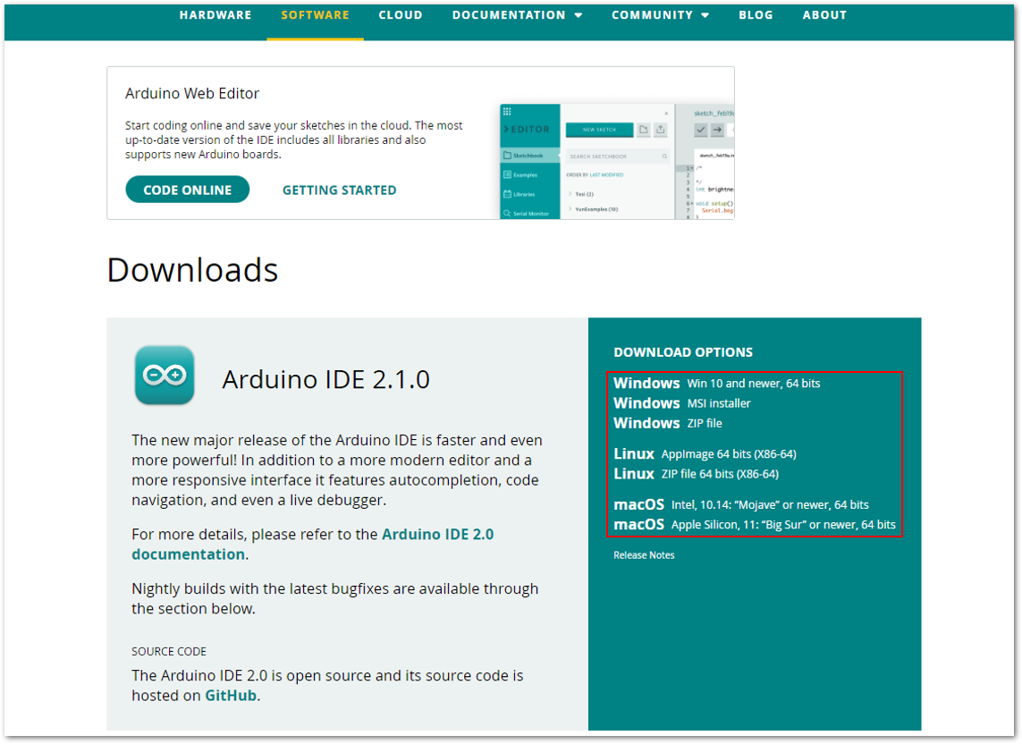 Figure 1: Download Options for the Arduino IDE
- Install the RAKwireless Arduino BSP for WisBlock by using the
package_rakwireless_index.jsonboard installation package. The WisBlock Core should now be available on the Arduino IDE. - Open the Arduino IDE and go to File > Preference.
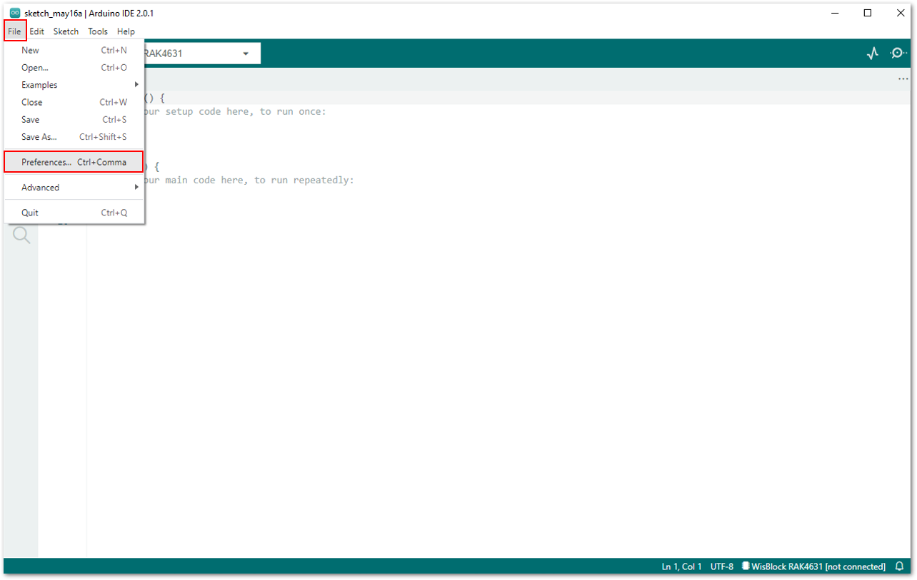 Figure 1: Preference Set-Up
- In the Preferences window, under the Settings tab, click the icon in line with Additional Boards Manager URLs.
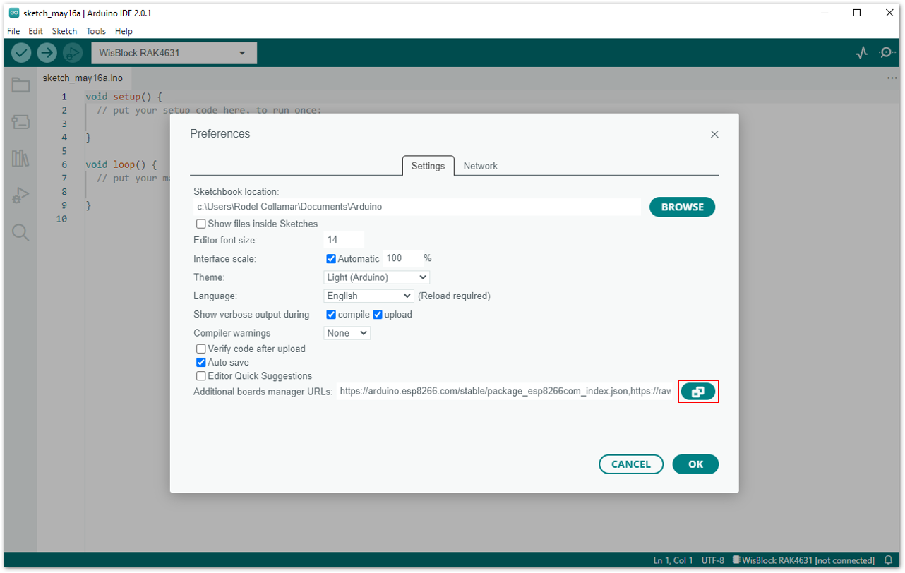 Figure 1: Preference Window
- A window will pop up. Copy the highlighted link and click OK.
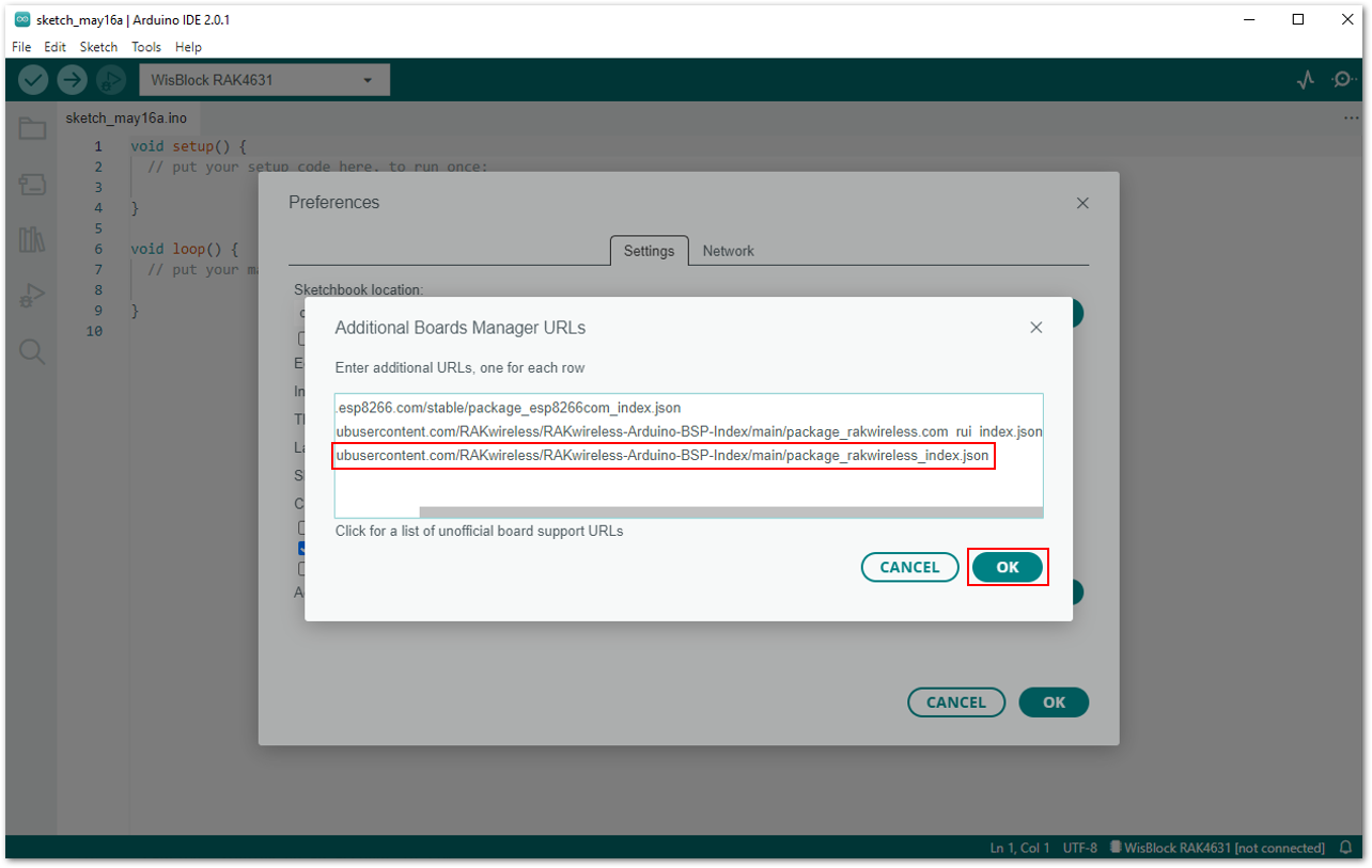 Figure 1: RAKwireless Arduino BSP
- Paste the link under the Additional boards manager URLs: field, and then click OK.
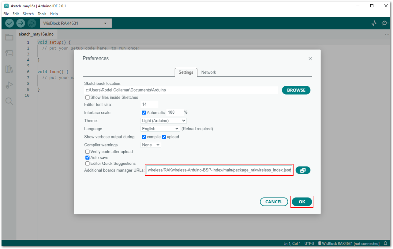 Figure 1: Completing the setup of the RAKwireless BSP support for the Arduino Board Manager
- In your Arduino IDE, go to Tools > Board:XXXXX > Boards Manager.
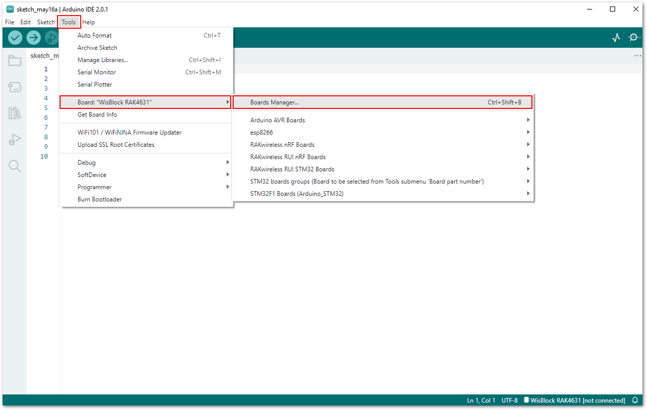 Figure 1: Opening the Boards Manager
Look for RAKwireless Boards by RAKwireless since you will be working with RAK4631 WisBlock Core. Choose the latest version, then install it. Once done, close the Board Manager.
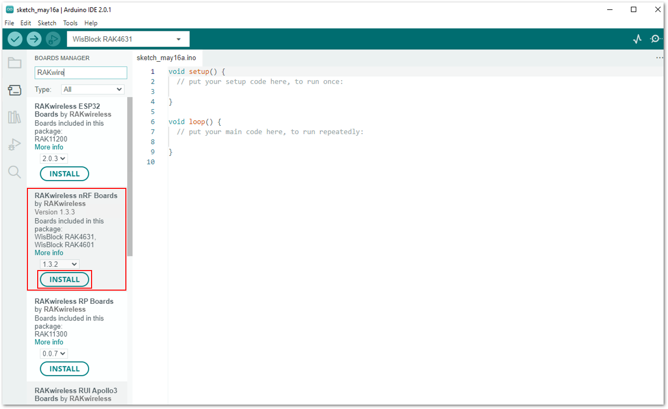 Figure 1: Installing the RAKwireless nRF Boards
The procedures above are applicable to all applications you will be using. Once done with the Arduino installation, you can visit these following links: