RAK10700 WisBlock GNSS Tracker for LoRaWAN Quick Start Guide
Prerequisites
What Do You Need?
Before going through each and every step in the installation guide of the GNSS Tracker, make sure to prepare the necessary items listed below:
Hardware Tools
- GNSS Tracker
- Micro USB Cable
- LoRaWAN gateway in range
- Windows PC
Software Tools
Serial Terminal Application, for example Termite Serial Terminal.
What's Included in the Package
- WisBlock GNSS Tracker
- IP65 enclosure (optional with solar panel)
- Micro USB cable
The GNSS module will take some time to get a location fix. The time depends on many factors but can take up to 45 seconds. The period of how often a location should be sent should be calculated taking into account:
- Time to get a location fix (up to 45 seconds);
- Local LoRaWAN regulations regarding duty cycles.
If the sending period is set too small (location cannot be fixed by the GNSS module), the device will not be able to send valid location data to the LoRaWAN server.
Battery Connection
RAK10700 can be powered via the USB cable or Li-Ion/LiPo battery via the dedicated connectors, as shown in Figure 1. The matching connector for the battery wires is an JST PHR-2 2 mm pitch female.
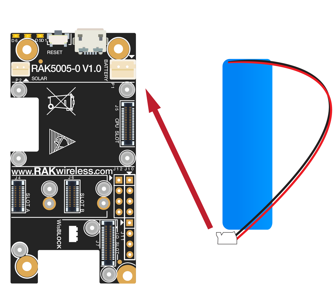 Figure 1: Battery Connection
The RAK10700 does come without a battery. You need to add a rechargeable battery and connect it to the battery connector inside the enclosure.
- Battery can cause harm if not handled properly.
- Only 3.7-4.2 V Rechargeable LiPo batteries are supported. It is highly recommended not to use other types of batteries with the system unless you know what you are doing.
- If a non-rechargeable battery is used, it has to be unplugged first before connecting the USB cable to the USB port of the board to configure the device. Not doing so might damage the battery or cause fire.
- Make sure the battery wires match the polarity on the RAK5005-O board used in the RAK10700. Not all batteries have the same wiring.
Product Configuration
Connecting to the GNSS Tracker
To interface with the GNSS Tracker with your Windows Machine, you need to have a serial terminal too. Any serial tool will work, but in this tutorial, the Termite Serial Terminal is used.
Once done, follow the listed steps to interface your GNSS Tracker with your computer.
- Connect the GNSS Tracker to the USB port of a general-purpose computer using a standard Micro - USB Cable.
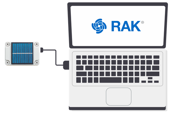 Figure 1: GNSS Tracker Connection
- Test if your GNSS Tracker can now communicate with the Serial Port Tool. Configure the serial communication tool by selecting the proper port and configuring the link as listed below, then click Open.
- COM: Choose the COM Port associated with the GNSS Tracker from the previous step. For this tutorial, the COM Port is COM4.
- Baud Rate: 115200 bps
- Data Bits: 8 bits
- Stop Bits: 1 bit
- Parity: NONE
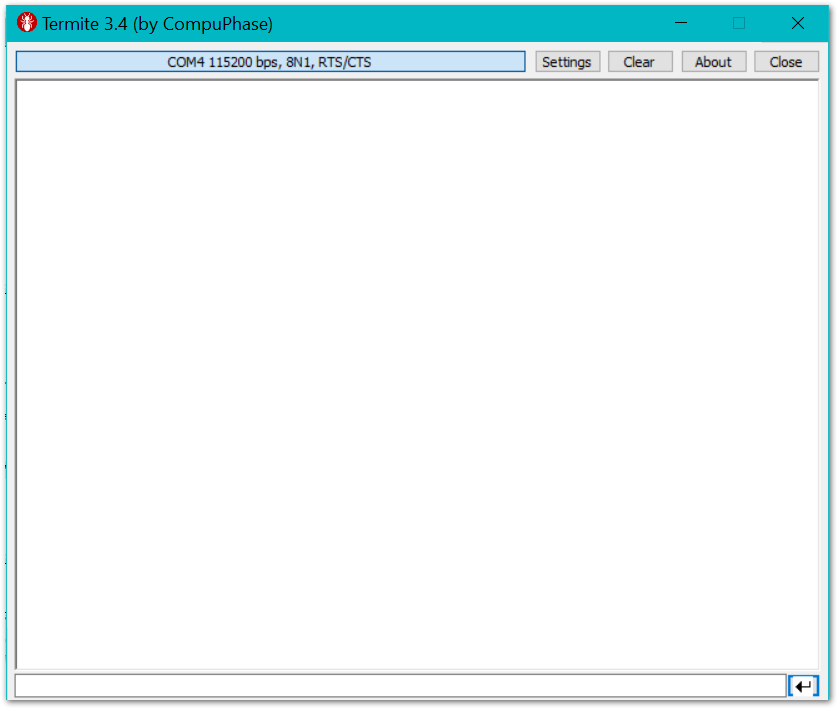 Figure 1: Connecting to the Serial Port Tool
- Verify your connection to the GNSS Tracker by sending the AT Command
AT+VER?. If the connection is successful, the firmware version of your GNSS Tracker should appear the same, as shown in Figure 4.
AT+VER=?
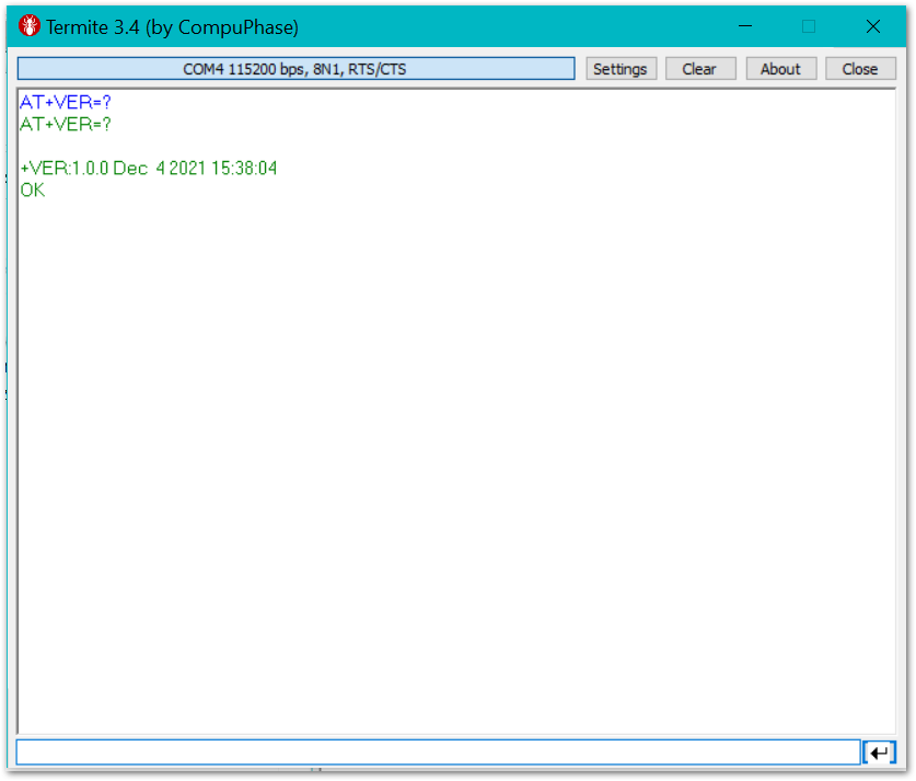 Figure 1: AT+Command Sample Serial Communication Test
Connecting to the Helium Network
Helium has quickly become the most widespread LPWAN communal network with more than 400,000 hotspots deployed globally at the beginning of 2021. All the RAKwireless node products are compatible with it, and the process of adding a device to the network is intuitive and straightforward.
This section will focus on giving a brief guide on how to connect the GNSS Tracker to the network console, assuming that there is a Helium Hotspot within range.
- Login or create your account on the Helium console page.
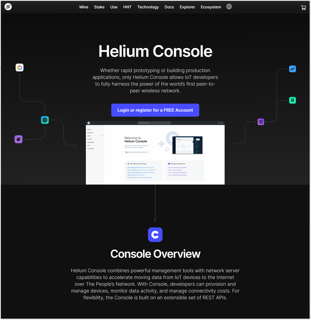 Figure 1: Helium console
- Once registered and logged in, you will end up at the home page where you can see your function tree on the left and your DC balance at the top, as well as several useful links.
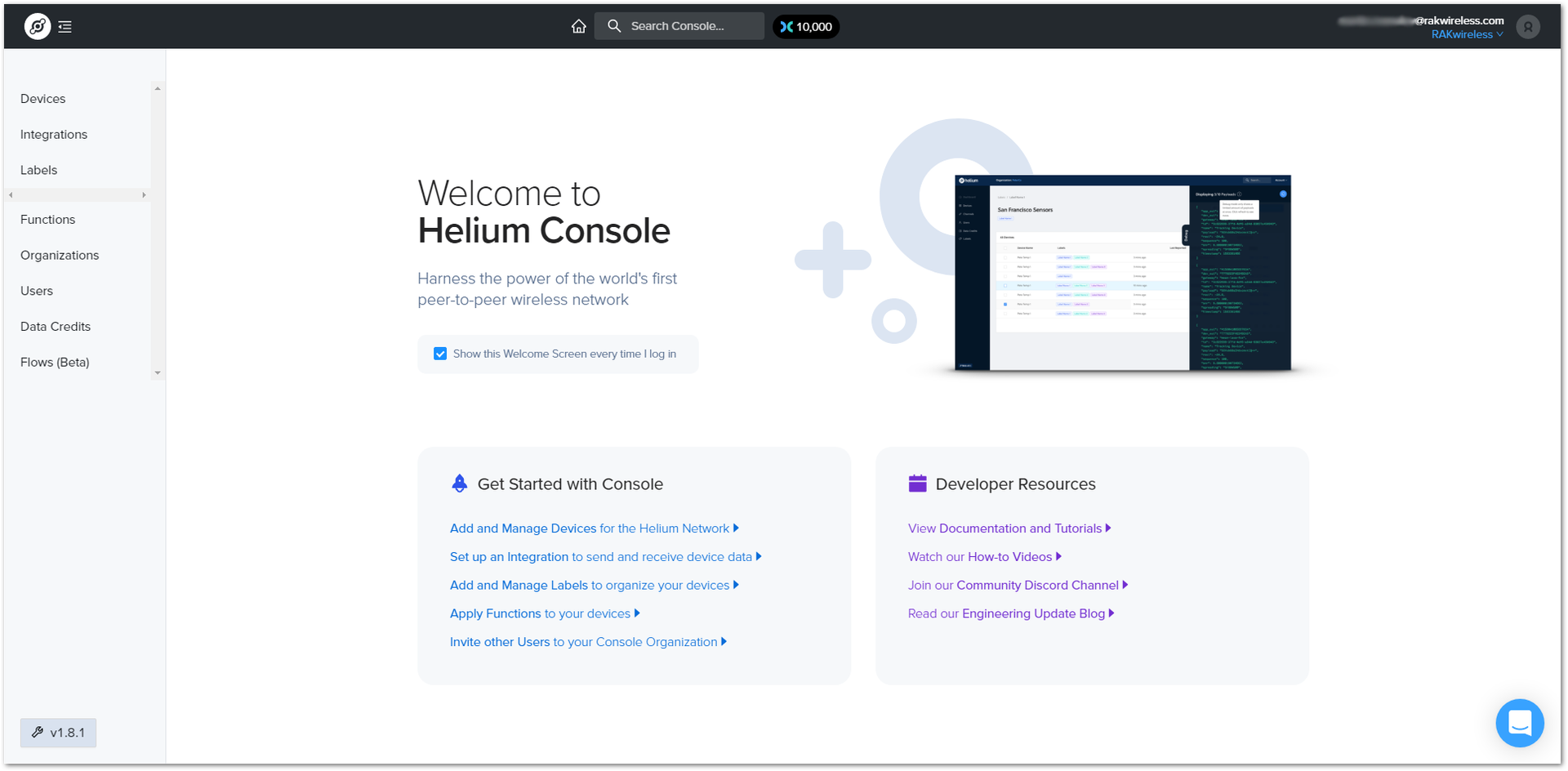 Figure 1: Helium console home screen
- Go to the Devices section in the function tree. If this is your first time doing this, there will be no devices registered. Click the + Add Device button to get started.
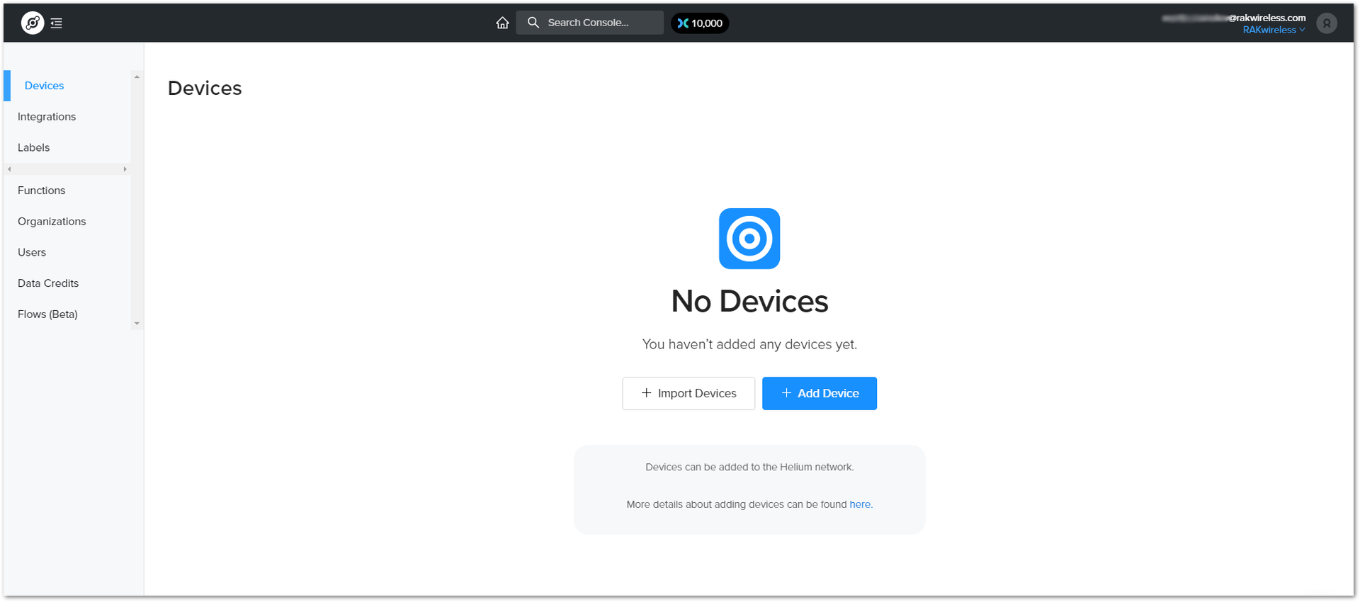 Figure 1: Devices section
- A window will pop up with a set of fields containing the device parameters required for its registration.
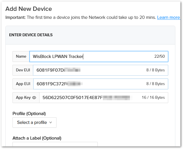 Figure 1: Adding a new device
- Fill in a name of your choosing. The Dev EUI, App EUI, and App Key will have random values generated for you by default. Press the eye icon to reveal the values. You can manually replace them with values of your own. For this tutorial, use the default values. Press the Submit button, and you are done.
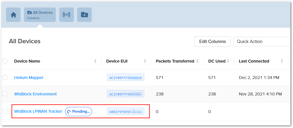 Figure 1: Helium devices
- To see the decoded values in the Helium Console, create a Flow that decodes the data.
- First, go to Functions in the Helium Console and create a new function. For the name, you can choose anything, the function type needs to be Decoder. For the format, choose Cayenne LPP.
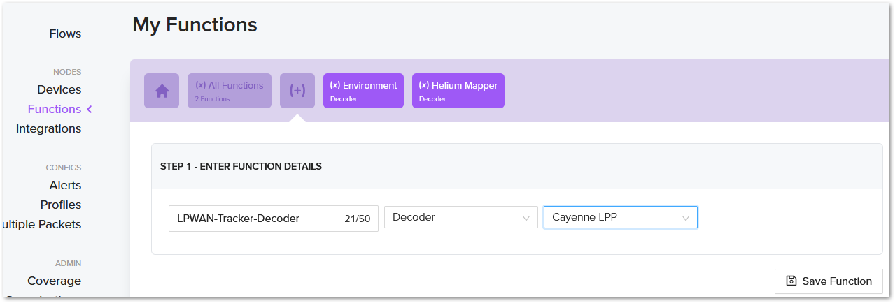 Figure 1: Helium decoder
- Next, go to Flows in the Helium Console and create a new flow. Connect your device to the flow that you just created.
 Figure 1: Helium flow
-
Now, your GNSS Tracker is registered and is awaiting activation. For this to happen, you need to import the Dev EUI, App EUI, and App Key in the GNSS Tracker using the Serial Port Tool.
-
Open the tool, select the desired port (default baud rate) and open it. Then start importing your settings.
-
Configure your LoRa band and activation mode. This tutorial will be using the AS923-3 band and OTAA (the only option available for now with Helium) with device class A (the default one and does not need configuring).
The different regions are selected by number:
- 0: AS923
- 1: AU915
- 2: CN470
- 3: CN779
- 4: EU433
- 5: EU868
- 6: KR920
- 7: IN865
- 8: US915
- 9: AS923-2
- 10: AS923-3
- 11: AS923-4
- 12: RU864
- Regional band and activation mode setting
AT+NJM=1
AT+BAND=10
- Enter the Dev UI
Use the command below by replacing the XXXX with your Device EUI from the Helium console:
AT+DEVEUI=XXXX
- Enter the App EUI
Update the APPEUI value of your LPWAN tracker by replacing the XXXX with the APPEUI value you get from the Helium Console:
AT+APPEUI=XXXX
- Enter the App Key
You also need to update the APPKEY by getting the 16-byte APPKEY from the Helium Console:
AT+APPKEY=XXXX
- Join Network
Finish executing the join command for the node to initiate the join procedure.
AT+JOIN=1:0:8:30
Once the procedure is initiated and successfully completed, you will have a notification in the serial console.
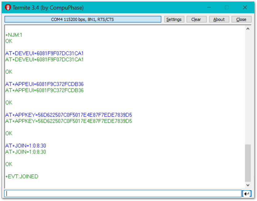 Figure 1: GNSS Tracker OTAA Parameters and Successful Join
If you take a look at the Helium console, you will also see the join request packets both in the graph and event log. Your node is now a part of the Helium Network.
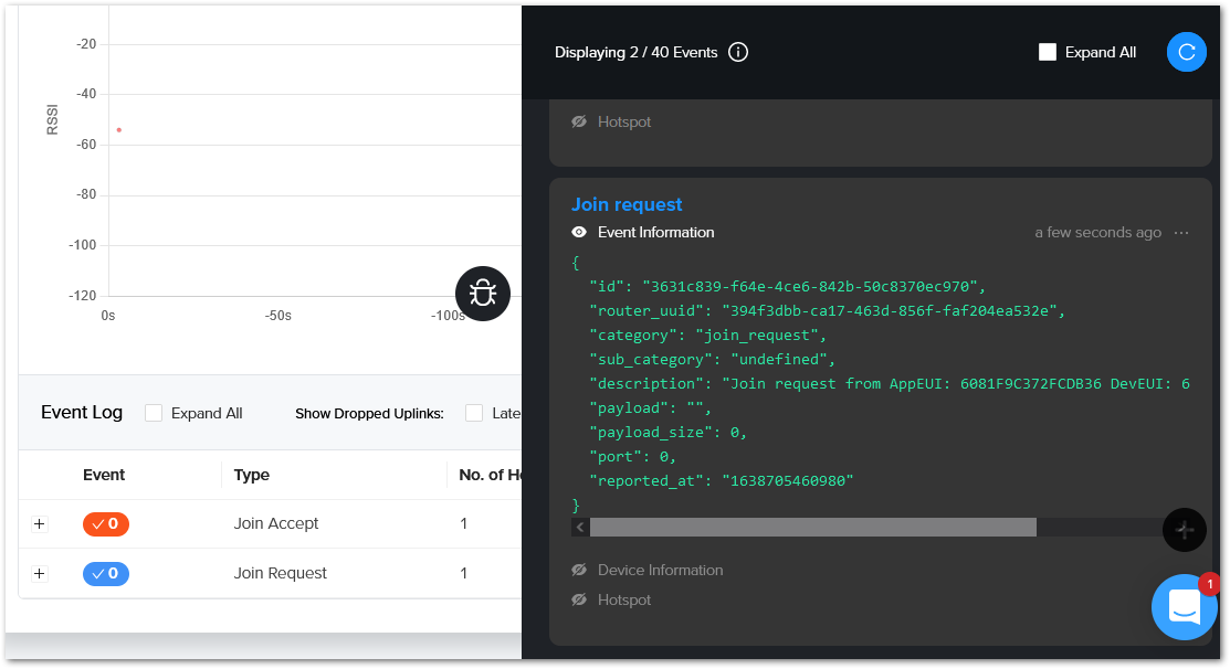 Figure 1: Helium console live device data
If your GNSS Tracker can get a location fix, you can see the live data in the Helium Console Debug window.
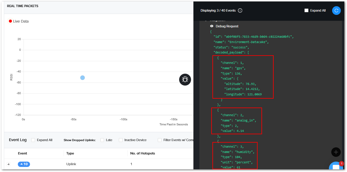 Figure 1: Helium console decode live device data
Connecting to The Things Network V3 (TTNv3)
In this section, it will be shown how to connect GNSS Tracker to The Things Stack.
First, log in to the TTNv3. To do so, head to the TTNv3 site. If you already have a TTN account, you can use your The Things ID credentials to log in.
 Figure 1: The Things Stack Home Page
 Figure 1: Console Page after a successful login
-
To connect GNSS Tracker to TTNv3, you should already have connected a gateway in range to TTNv3. Or, you have to be sure that you are in the range of a public gateway.
-
This tutorial is for the EU868 Frequency band.
Adding an Application
- If you do not have created applications yet, to create an application, choose Create an application. If you have created applications before, navigate through Go to applications > + Add application.
 Figure 1: Create an application page
-
Fill in the needed information. After filling in, click Create application.
- Owner - Automatically filled by The Things Stack, based on your account or created organization.
- Application ID - This will be the unique ID of your application in the Network. ID must contain only lowercase letters, numbers, and dashes (-).
- Application name (optional) - This is the name of your application.
- Description (optional) – Description of your application. Optional application description; can also be used to save notes about the application.
 Figure 1: Create an application page
OTAA Mode
Register the Device
- From the Application Overview page, click on + Add end device.
 Figure 1: Adding a device in OTAA mode
- Below the Register end device heading, you can find two options for registering a device. Choose Manually.
- For Activation mode, choose Over the air activation (OTAA).
- For the LoRaWAN version, choose MAC V1.0.2 (GNSS Tracker is LoRaWAN 1.0.2 fully compliant).
 Figure 1: Registering the device in OTAA mode
- To get to the next step of the registration, click Start.
 Figure 1: Basic settings for OTAA mode
-
Fill in the basic settings for the device:
- End device ID - This is the unique identifier for your GNSS Tracker in your application. You need to enter this manually. The End device ID must contain only lowercase letters, numbers, and dashes (-).
- AppEUI - The AppEUI uniquely identifies the owner of the end device. It is provided by the device manufacturer. To get the AppEUI, connect your device via USB cable to your computer. Open Serial Port Tool, choose the correct COM port and BaudRate, and run the following command:
AT+STATUS=?
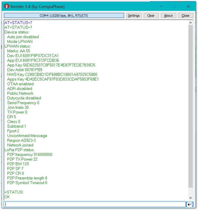 Figure 1: AppEUI of the device
- DevEUI - The unique identifier for this end device. It can be found on a sticker on the back of the device.
- End device name (optional) - A unique, human-readable identifier for your device. You make it up, so be creative. Device IDs cannot be used by multiple devices within the same application.
- End device description (optional) - Optional end device description; can also be used to save notes about the end device.
- Click Network layer setting.
 Figure 1: Network layer setting for OTAA mode
- Here, you must configure the Network layer settings for the device:
- Frequency plan - The frequency plan used by the end device. Note that, for this tutorial, the frequency plan used is Europe 863-870 MHz (SF9 for RX2 – recommended).
- Regional Parameters version - The Regional Parameters specify frequency, dwell time, and other communication settings for different geographical areas. The Regional Parameters version is the version of the LoRa Alliance specification which your device supports. This should be provided by the device manufacturer in a datasheet. For this example, PHY V1.0.2 REV A is chosen.
- LoRaWAN class capabilities – Here you can select if your device supports Class B, Class C, or both.
- In the Advanced settings, you can configure additional settings for your device.
 Figure 1: Advanced network layer settings of the device
For this example, these settings will be left as default.
- Click Join settings.
 Figure 1: Join settings for OTAA mode
- Fill in the Application key (AppKey) to secure communication between the end device and the application. The AppKey can be generated automatically by clicking the Generate button next to the AppKey field.
 Figure 1: Generate the AppKey
- In the Advanced settings, you can configure more options about your device.
 Figure 1: Advanced join settings for OTAA mode
For this example, these settings will be left as default.
- Finally, to finish registering your device, click Add end device.
Configuring the Device in OTAA Mode
- For configuring the node, you will need the following three parameters: Device EUI, Application EUI, and Application Key. You can see them all on the Device Overview page. But since the two EUI's come with the device, you only need the Application Key from there.
 Figure 1: OTAA device parameters
- Using the Serial Port Tool, set the join mode, device class, and your LoRaWAN region to your correct frequency band, with the following set of AT commands:
- For the join mode (OTAA):
AT+NJM=1
- For the class (Class A):
AT+CLASS=A
- For the region:
AT+BAND=5
Remember to replace the frequency band with the one for your LoRaWAN region. Check first your frequency plan.
 Figure 1: Setting up the GNSS Tracker operation mode
The following tutorial is based on using the EU868 frequency band.
- Now that those parameters are set, enter the App Key, using the command below. Remember to replace the
XXXXwith the corresponding parameter value for your particular case.
AT+APPKEY=XXXX
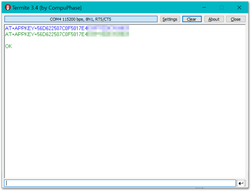 Figure 1: Setting up the GNSS Tracker OTAA parameters
- Finally, execute the join command:
AT+JOIN=1:0:8:30
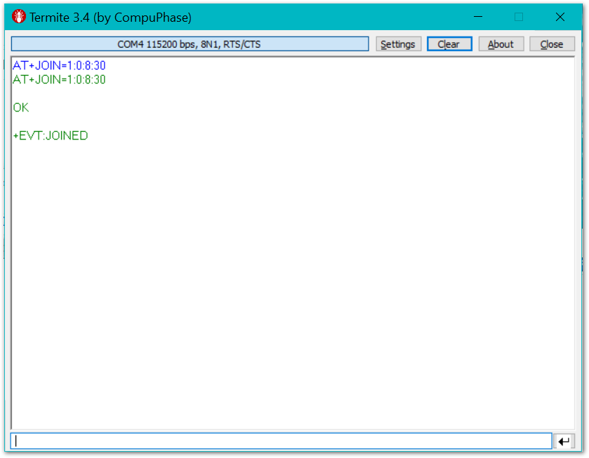 Figure 1: Join command
If you get a response in the Live data feed in The Things Stack, it means your GNSS Tracker is successfully connected.
 Figure 1: Sending data to The Things Stack from GNSS Tracker
Connecting with ChirpStack
In this section, a practical exercise will be performed to show how to connect the GNSS Tracker to the ChirpStack platform.
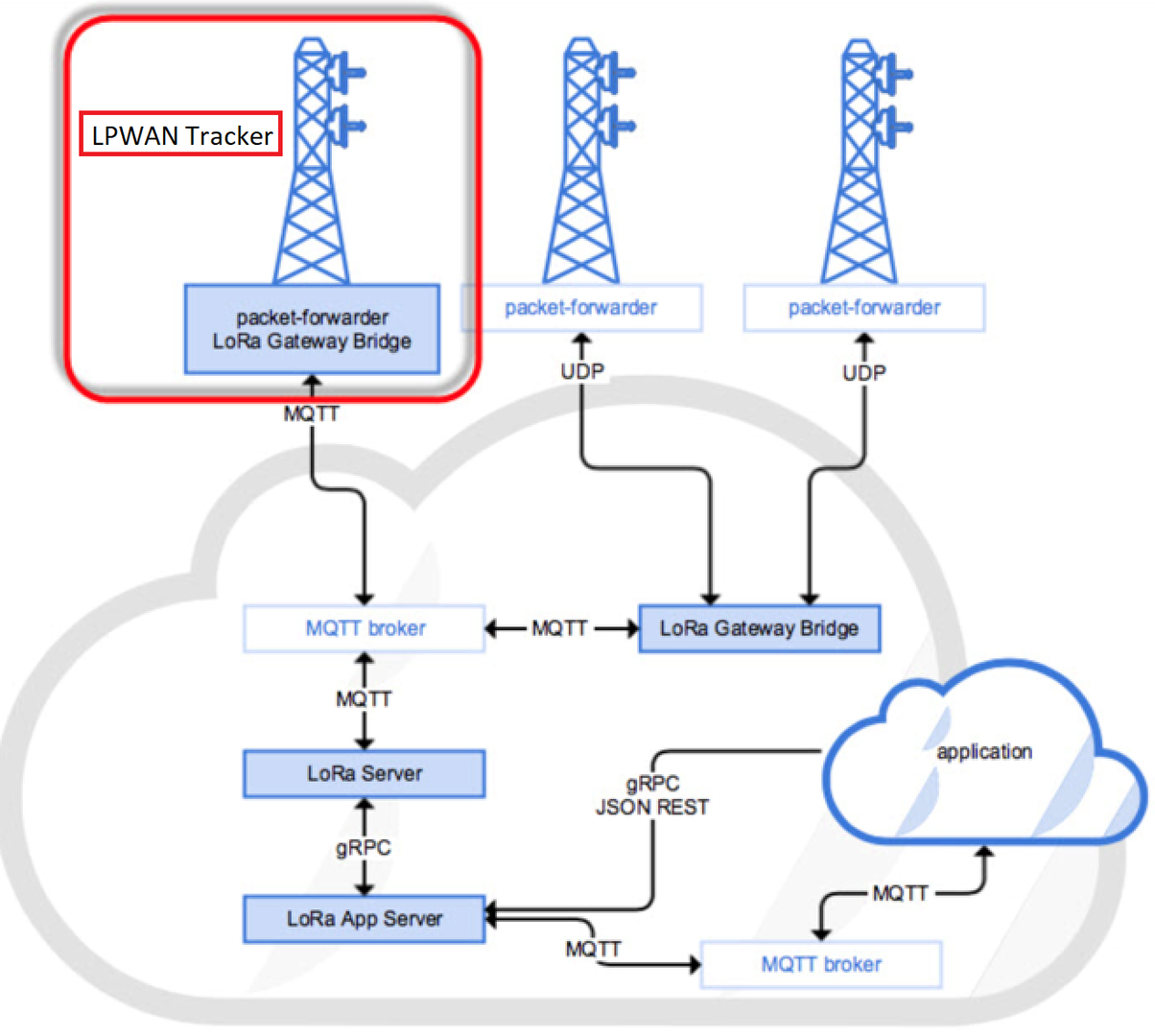 Figure 1: GNSS Tracker in the context of the ChirpStack platform
The ChirpStack, previously known as the LoRaServer project, provides open-source components for building LoRaWAN networks. Like the case of TTN, the GNSS Tracker is located in the periphery and transmits the data to the backend servers through a LoRa gateway. Learn more about ChirpStack.
In this guide, it is assumed that you are using a RAK LoRa gateway, such as RAK7249. The gateway must be configured and registered previously to a Chirpstack deployment. For further information, check the Chirpstack documents for more details.
In this section, you need the following requirements:
- A ChirpStack deployment
- Access to a LoRaWAN gateway registered at the ChirpStack server
- Chirpstack already setup with a Network Server and Service Profile
- Serial Port Tool
- GNSS Tracker
Before you start, you must choose which mode you are going to use, whether in OTAA or ABP mode, to register the device to the network server.
Sign up and Log inSign in to Chirpstack with your username and password.
Create a New Application
- Go to the Application section, as shown in Figure 34.
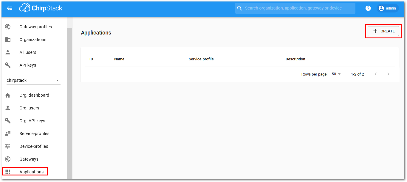 Figure 1: Application Section of ChirpStack LoRaServer
- By default, you should create a new Application, although you can reuse the existing ones. For this setup, create a new Application by clicking on the “CREATE” button, and filling the required parameters, as shown in Figure 35 and Figure 36.
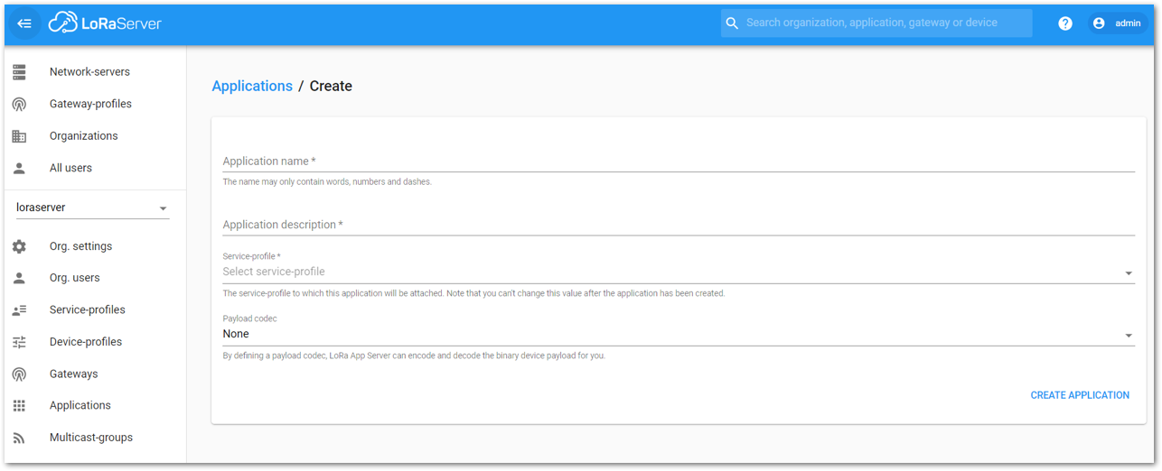 Figure 1: Creating a New Application
- For this setup, create an Application named RAK-PH-Testapp. You can choose any name that fits better for you.
ChirpStack LoraServer supports multiple system configurations, with only one by default.
- Service profile: field is to select the system profile.
- Payload codec: is the parsing method for selecting load data. Choose Cayenne LPP for the GNSS Tracker, because this format is used for the payload.
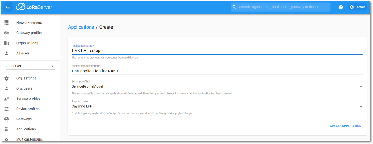 Figure 1: Filling Parameters of an Application
Create Device Profiles
Before you can add devices to the newly created application, you need to define Device Profiles. Device profiles define basic settings of devices, like join mode (OTAA or ABP) and the payload decoder used for this device.
Create Profile for OTAA Join Mode
- Go to Device-profiles, then click the CREATE button.
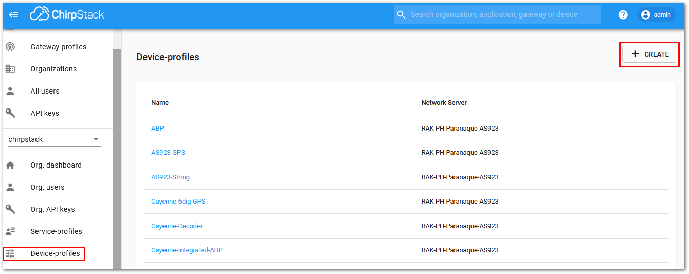 Figure 1: Filling Parameters of an Application
- You will create two profiles. The only difference is the Join mode (OTAA or ABP).
Parameters for the Device Profile:
| Field | Entry |
|---|---|
| Device-profile name | Choose a name that describes the usage |
| Network-server | Name of the Network Server (click to see available servers) |
| LoRaWAN MAC version | GNSS Tracker uses 1.0.2 |
| LoRaWAN Regional Parameters revision | GNSS Tracker uses B |
| Max EIRP | Leave it a 0 |
| Uplink interval (seconds) | Set to a value matching with the sending frequency of the GNSS Tracker |
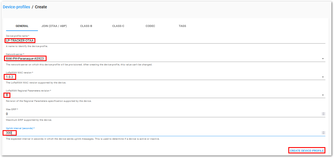 Figure 1: Create Device Profile
- Switch to Join (OTAA/ABP) tab. The only thing here is to check the Device supports OTAA check box.
 Figure 1: Create Device Profile - Join Settings
- Switch to the CODEC tab. Select Cayenne LPP as payload decoder, then click CREATE DEVICE-PROFILE.
 Figure 1: Create Device Profile - Select Payload Decoder
Create Profile for ABP Join Mode
- Go to Device-profiles, then click the CREATE button.
 Figure 1: Filling Parameters of an Application
- You will create two profiles. The only difference is the Join mode (OTAA or ABP).
Parameters for the Device Profile:
| Field | Entry |
|---|---|
| Device-profile name | Choose a name that describes the usage |
| Network-server | Name of the Network Server (click to see available servers) |
| LoRaWAN MAC version | GNSS Tracker uses 1.0.2 |
| LoRaWAN Regional Parameters revision | GNSS Tracker uses B |
| Max EIRP | Leave it a 0 |
| Uplink interval (seconds) | Set to a value matching with the sending frequency of the GNSS Tracker |
 Figure 1: Create Device Profile
- Switch to Join (OTAA/ABP) tab. Make sure Device supports OTAA is not checked.
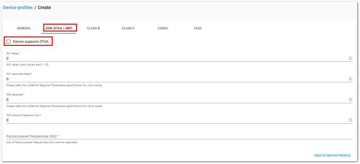 Figure 1: Create Device Profile - Join Settings
- Switch to the CODEC tab. Select Cayenne LPP as payload decoder, then click CREATE DEVICE-PROFILE
 Figure 1: Create Device Profile - Select Payload Decoder
Register a New Device
- Choose the Application created in the previous step, then select the DEVICES tab, as shown in Figure 45 and Figure 46.
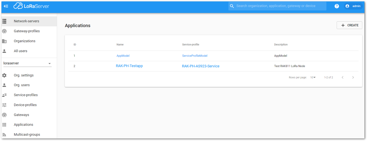 Figure 1: List of Applications Created
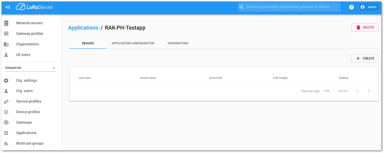 Figure 1: Device Tab of an Application
- Once inside of the DEVICE tab, create a new device (LoRa node) by clicking on the “+ CREATE” button.
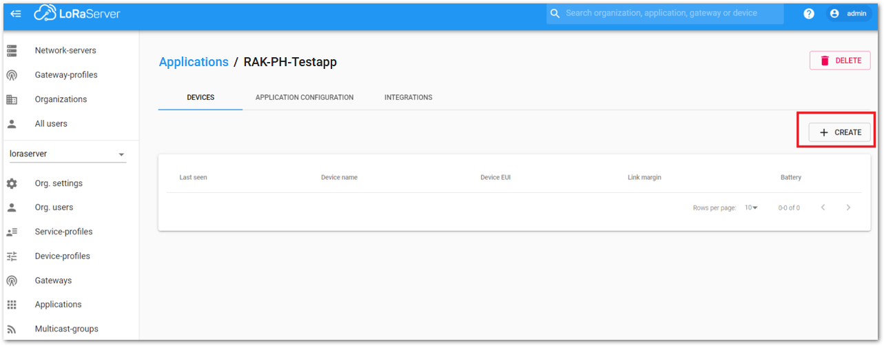 Figure 1: Add a New Device at Device Tab
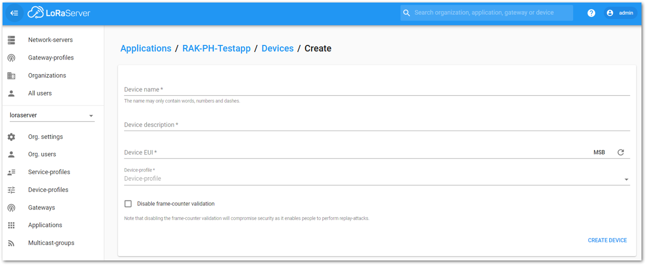 Figure 1: New Device Registration Form
- Once the node is created, fill in the necessary data. You can generate a Device EUI automatically by clicking the following icon, or you can write a correct Device EUI in the edit box.
- Device name and Device description: These are descriptive texts about your device.
- Device EUI: Enter the device EUI of your GNSS Tracker here.
- Application Key: This key is required during the OTAA join process. You can use the AppKey from the GNSS Tracker here.
- Device Profile:
- If you want to join in OTAA mode, select “DeviceProfile_OTAA”.
- If you want to join in ABP mode, select “DeviceProfile_ABP”.
- Get the DevEUI and AppKey from the GNSS Tracker using the command
AT+STATUS=?using the Serial Port Tool
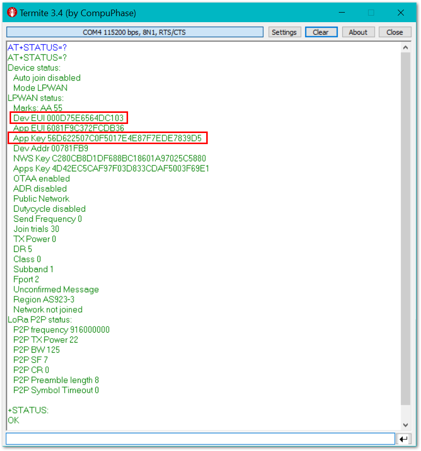 Figure 1: Get DevEUI and AppKey from the GNSS Tracker
- Enter the values in Chirpstack.
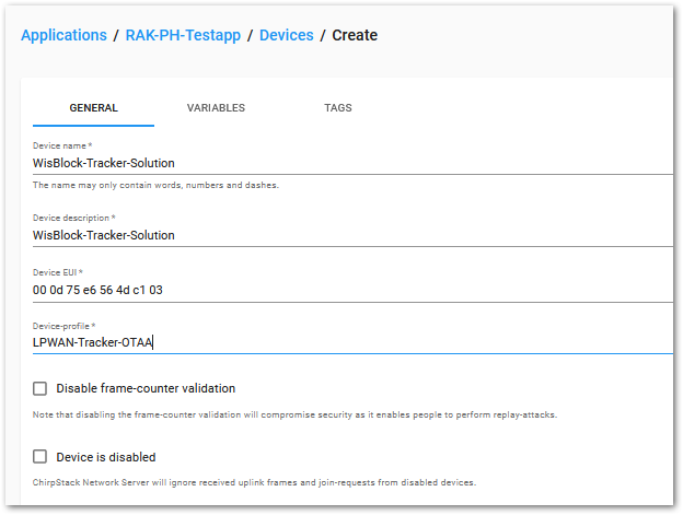 Figure 1: Enter Device EUI
 Figure 1: Enter Application Key
LoRaWAN Join Mode
In LoRaWAN, there are two ways a node can connect itself to the LoRaWAN network. This is referred to as Join Mode. LoRaWAN allows the OTAA mode and the ABP mode. In this section, the configuration process of these two modes, both on the platform side and the node side will be explained.
OTAA Mode
Configure the OTAA Mode on the Platform
You have created the device before as an OTAA device, and it can be used to connect the GNSS Tracker to Chirpstack using OTAA join mode.
Standard OTAA mode requires the Device EUI, Application Key, and the Application EUI. But in ChirpStack’s implementation, only the Device EUI and the Application Key are mandatory. The Application EUI is not required and is not recorded in the Application tab. Nevertheless, the Application EUI is a mandatory parameter in the LPWAN Tracker’s firmware. To resolve this mismatch, you can reuse the Device EUI as the Application EUI during the configuration on the side of the node.
Configure the OTAA Mode on the GNSS Tracker
The GNSS Tracker supports a series of AT commands to configure its internal parameters and control the functionalities of the module.
To set up the GNSS Tracker to join ChirpStack using OTAA, start by connecting the GNSS Tracker to the Computer (see Figure 2). Open the RAK Serial Port Tool and wait for the communication to start. It is recommended to test the serial communication by sending either of these two AT commands:
AT+STATUS=?
AT+VER=?
As an example, the following are the list of the parameters you need to configure in GNSS Tracker:
- LoRa join mode: OTAA
- LoRa class: Class A
- LoRa region: AS923-3
- Device EUI: 000d75e6564dc103
- Application EUI: Not used by Chirpstack
- Application Key: 56D622507C0F5017E4E87F7EDE7839D5
- Set the LoRa join mode to OTAA.
AT+NJM=1
- Set the LoRa class to Class A.
AT+CLASS=A
- Set the frequency/region to AS923-3.
- Refer to the GNSS Tracker Datasheet for the list of supported frequencies.
AT+BAND=10
- Set the Device EUI (if different to default GNSS Tracker DevEUI).
AT+DEVEUI=000d75e6564dc103
- Set the Application Key (if different to default GNSS Tracker AppKey).
AT+APPKEY=56D622507C0F5017E4E87F7EDE7839D5
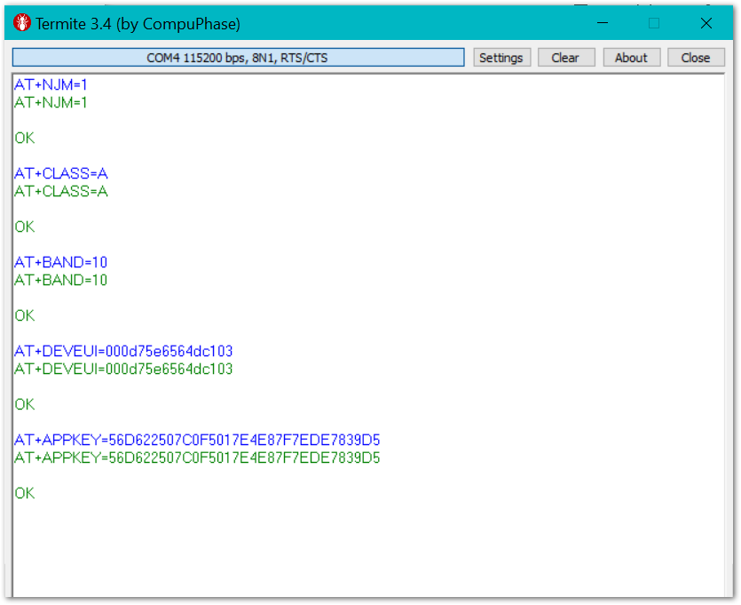 Figure 1: Setting LoRa Application Key Parameter
After configuring all the parameters, you need to reset the GNSS Tracker to save the parameters.
- After resetting, start to join.
AT+JOIN=1:0:8:30
After 5 or 6 seconds, if the request is successfully received by a LoRa gateway, then you should see the messages shown in Figure 53.
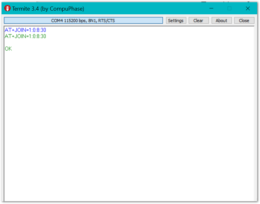 Figure 1: Chirpstack OTAA Join the Network via Serial Port Tool
- You can then see the JoinRequest and JoinAccept on the ChirpStack page.
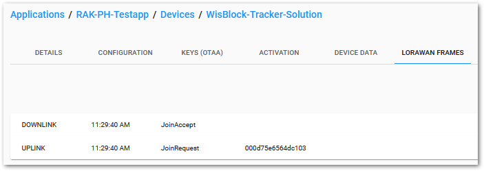 Figure 1: Checking LoRaWAN Joint Request in Chirpstack OTAA Console
- On the ChirpStack platform, you should also see the messages in the LORAWAN FRAMES tab, as shown in Figure 54.
By convention, messages sent from nodes to gateways are considered as Uplinks, while messages sent by gateways to nodes are considered as Downlinks.
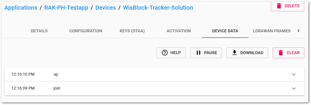 Figure 1: Chirpstack Data Received Preview
As the payload decoder is set as Cayenne LPP in the device profile, the data is decoded and you can see the values when you open the received frame in the Chirpstack Device Data tab:
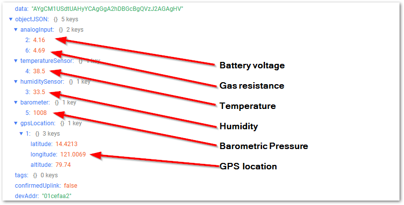 Figure 1: Chirpstack Data Received Decoded Preview
ABP Mode
Configure the ABP Mode on the Platform
During the registration of a new device for OTAA join mode, you select LPWAN-Tracker-OTAA. To switch the device to ABP join mode, you need to change the Device Profile from LPWAN-Tracker-OTAA to LPWAN-Tracker-ABP, as shown in Figure 57, in the device CONFIGURATION tab
Check Disable counting frame verification. During the test, when the module is restarted, the frame counting number will be also be restarted from zero. This would cause a synchronization problem with the ChirpStack server treating it as a replay attack. For the testing purpose, it is safe to disable this feature, but remember to activate it in a production environment.
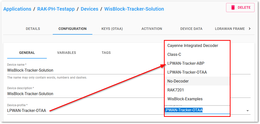 Figure 1: ChirpStack Console, Configuring a Device
Next, get the Device Address, Application Session Key, and Network Session Key from the device using the Serial Port Tool.
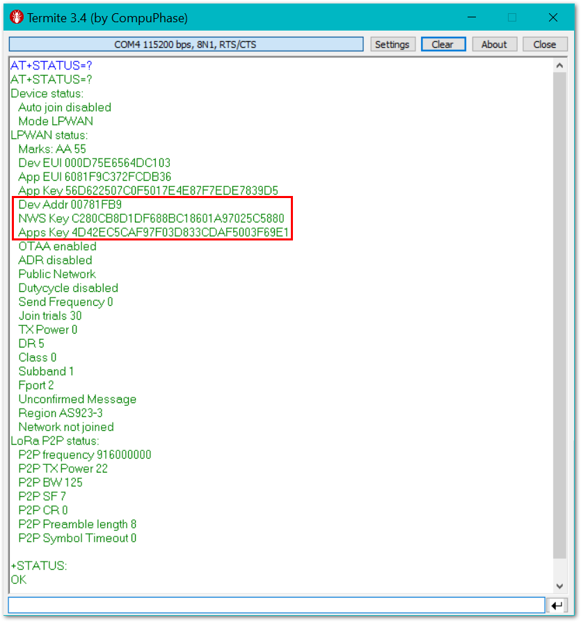 Figure 1: ChirpStack Console, Configuring a Device
In Chirpstack, after selecting the ABP mode, the following parameters appear in the Activation tab:
- Device address
- Network Session Key
- Application Session Key
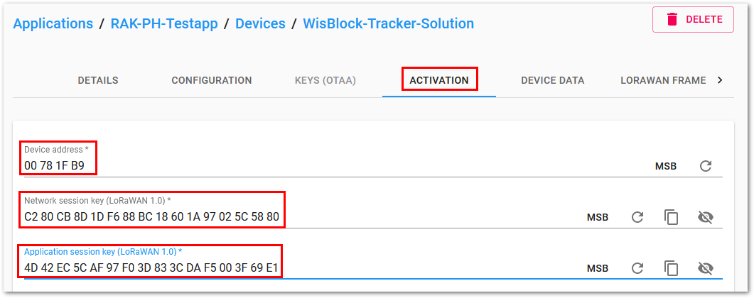 Figure 1: Chirpstack ABP Activation Parameters Needed
- Set the parameters with the values received from the device.
Configure the ABP Mode on the GNSS Tracker
In the following steps, you will configure the GNSS Tracker to work in the ABP mode. To set up the GNSS Tracker to join ChirpStack using ABP start by connecting the GNSS Tracker to the Computer (see Figure 2). Open the Serial Port Tool and wait for the communication to start. It is recommended to test the serial communication by sending either of these two AT commands:
AT+STATUS=?
AT+VER=?
As an example, the following are the list of the parameters you need to configure in GNSS Tracker:
- LoRa join mode: ABP
- LoRa class: Class A
- LoRa region: AS923-3
- Device address: 00781FB9
- Network Session Key: C280CB8D1DF688BC18601A97025C5880
- Application Session Key: 4D42EC5CAF97F03D833CDAF5003F69E1
- Set LoRa join mode to ABP.
AT+NJM=0
- Set LoRa class to Class A.
AT+CLASS=A
- Set the frequency/region to AS923-3.
- Refer to the GNSS Tracker Datasheet for the list of supported frequencies.
AT+BAND=10
- Set the Device Address (if different to default GNSS Tracker Device Address).
AT+DEVADDR=00781FB9
- Set the Network Session Key (if different to default GNSS Tracker Network Session Key).
AT+NWKSKEY=C280CB8D1DF688BC18601A97025C5880
- Set the Application Session Key (if different to default GNSS Tracker Application Session Key).
AT+APPSKEY=4D42EC5CAF97F03D833CDAF5003F69E1
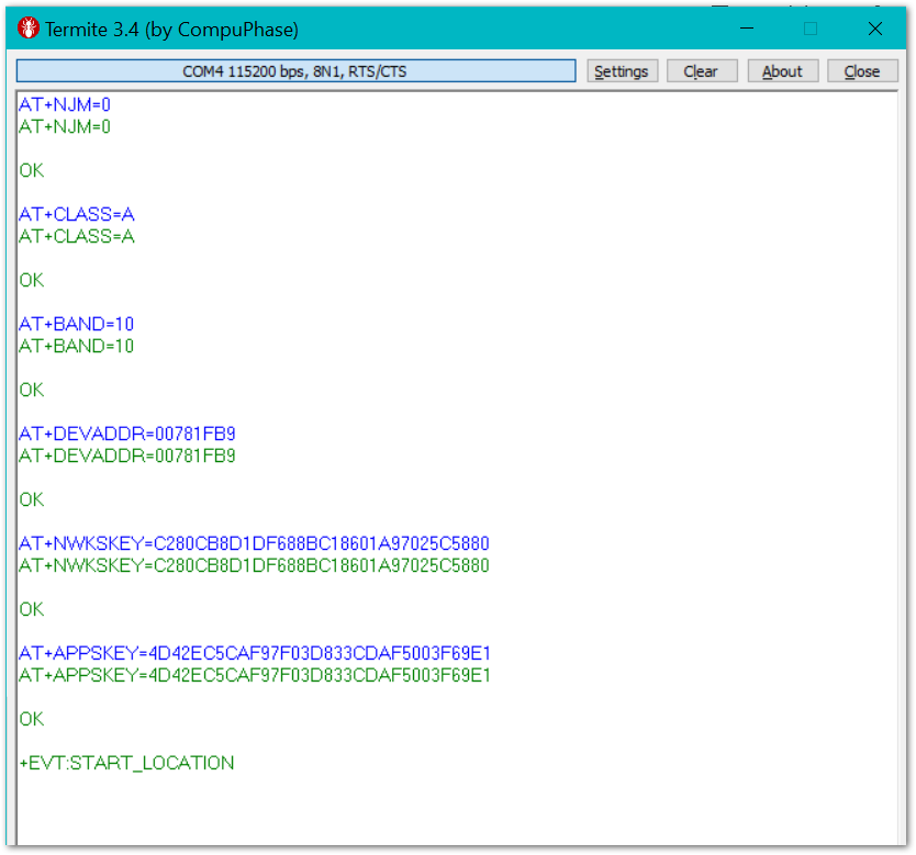 Figure 1: Setting LoRa Network Session Parameter
After configuring all the parameters, you need to reset the GNSS Tracker to save the parameters.
- After resetting GNSS Tracker, join in ABP mode.
AT+JOIN=1:0:8:30
By using the ABP mode in the LoRaWAN protocol, it doesn’t require to join a network before sending the LoRaWAN package. But to keep the consistency of internal states of the firmware of the GNSS Tracker, it is still required to send the AT+JOIN=1:0:8:30 command in the ABP mode. This time, the firmware should reply almost immediately with an “OK”.
- Once the GNSS Tracker joined into a LoRaWAN network, it will start to send periodically the data collected from the GPS and other sensors. Then go to the ChirpStack platform to confirm that the messages are properly received, as shown in Figure 61.
 Figure 1: Data Collected in ChirpStack
- As the payload decoder is set as Cayenne LPP in the device profile, the data is decoded and you can see the values when you open the received frame in the Chirpstack Device Data tab:
 Figure 1: Chirpstack Data Received Decoded Preview
Using LoRa P2P
LoRa P2P is a transmitting packet using the LoRa technology. Different from LoRaWAN, there is no transmission protocol available. Devices do not need to be registered on a server. LoRa P2P is not encrypting the packets during transmission. LoRa P2P packets cannot be received by LoRaWAN gateways.
To use LoRa P2P, you need at least two (2) devices. One device (the GNSS Tracker) is the sending device, and the other is the receiving device. To be able to transmit packets between the two devices, both devices need to be set up to use the same frequency, spreading factor (SF), bandwidth (BW), coding rate (CR), and preamble length (PL). In this example we setup both devices to
| Parameter | Value |
|---|---|
| Frequency | 916100000 Hz |
| SF | 7 |
| BW | 125 kHz |
| CR | 4/5 |
| PL | 8 |
- Set up P2P parameters, as shown in the table above.
AT+P2P=916100000:7:125:0:8:22
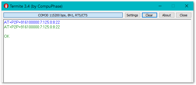 Figure 1: LoRa P2P Setup
- If the receiver is set up with the same parameters, it will receive the packets from the GNSS Tracker.
 Figure 1: LoRa P2P Data Received
- The data is decoded in Cayenne LPP format and will require a decoder in your receiver module to get the values.
The next paragraph is explaining the payload format. If your receiver is using firmware based on Arduino, you can use a Cayenne LPP Decoder library like the CayenneLPPdec to decode the payload.
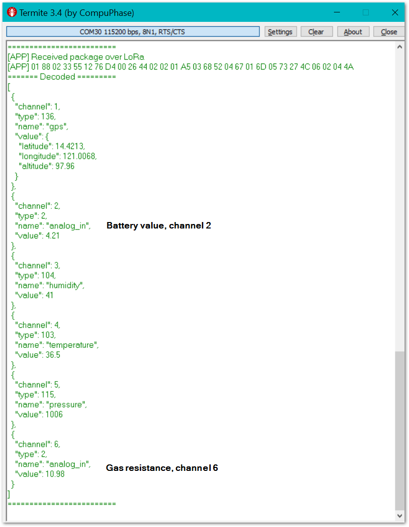 Figure 1: LoRa P2P Received Decoded Preview
Decoding the Payload
Cayenne LPP Data Format
The Cayenne Low Power Payload (LPP) provides a convenient and easy way to send data over LPWAN networks such as LoRaWAN. The Cayenne LPP is compliant with the payload size restriction, which can be lowered down to 11 bytes, and allows the device to send multiple sensor data at a time or split into several frames.
The Data Channel uniquely identifies each sensor or actuator within a device. The acceptable range is from 0 to 64. The device developer is responsible to assign a unique channel for each of the device's sensor and actuator and conform to it across the device life cycle.
Data Types are based on the IPSO Alliance Smart Objects Guidelines, which identify each data type with an "Object ID". However, as shown below, a conversion is made to fit the Object ID into a single byte.
LPP_DATA_TYPE = IPSO_OBJECT_ID - 3200
Each data type can use 1 or more bytes to send the data according to the following table:
| Type | IPSO | LPP | Hex | Data Size | Data Resolution per bit |
|---|---|---|---|---|---|
| Digital Input | 3200 | 0 | 0 | 1 | 1 |
| Digital Output | 3201 | 1 | 1 | 1 | 1 |
| Analog Input | 3202 | 2 | 2 | 2 | 0.01 Signed |
| Analog Output | 3203 | 3 | 3 | 2 | 0.01 Signed |
| Illuminance Sensor | 3301 | 101 | 65 | 2 | 1 Lux Unsigned MSB |
| Presence Sensor | 3302 | 102 | 66 | 1 | 1 |
| Temperature Sensor | 3303 | 103 | 67 | 2 | 0.1 °C Signed MSB |
| Humidity Sensor | 3304 | 104 | 68 | 1 | 0.5 % Unsigned |
| Accelerometer | 3313 | 113 | 71 | 6 | 0.001 G Signed MSB per axis |
| Barometer | 3315 | 115 | 73 | 2 | 0.1 hPa Unsigned MSB |
| Gyrometer | 3334 | 134 | 86 | 6 | 0.01 °/s Signed MSB per axis |
| GPS Location | 3336 | 136 | 88 | 9 | Latitude : 0.0001 ° Signed MSB Longitude : 0.0001 ° Signed MSB Altitude : 0.01 meter Signed MSB |
Data Format Used
The packet data is based on the Cayenne LPP packet format, which makes it very easy to decode because most LoRaWAN servers and Integrations support this format already. The data format is like this:
uint8_t data_flag1 = 0x01;  // 1 Cayenne LPP channel
uint8_t data_flag2 = 0x88;  // 2 Cayenne LPP location
uint8_t lat_1 = 0;      // 3
uint8_t lat_2 = 0;      // 4
uint8_t lat_3 = 0;      // 5
uint8_t long_1 = 0;     // 6
uint8_t long_2 = 0;     // 7
uint8_t long_3 = 0;     // 8
uint8_t alt_1 = 0;      // 9
uint8_t alt_2 = 0;      // 10
uint8_t alt_3 = 0;      // 11
uint8_t data_flag3 = 0x02;  // 12 Cayenne LPP channel
uint8_t data_flag4 = 0x02;  // 13 Cayenne LPP analog value
uint8_t batt_1 = 0;     // 14
uint8_t batt_2 = 0;     // 15
uint8_t data_flag5 = 0x03;  // 16 Cayenne LPP channel
uint8_t data_flag6 = 0x68;  // 17 Cayenne LPP humidity
uint8_t humid_1 = 0;    // 18
uint8_t data_flag7 = 0x04;  // 19 Cayenne LPP channel
uint8_t data_flag8 = 0x67;  // 20 Cayenne LPP temperature
uint8_t temp_1 = 0;     // 21
uint8_t temp_2 = 0;     // 22
uint8_t data_flag9 = 0x05;  // 23 Cayenne LPP channel
uint8_t data_flag10 = 0x73; // 24 Cayenne LPP barometric pressure
uint8_t press_1 = 0;    // 25
uint8_t press_2 = 0;    // 26
uint8_t data_flag11 = 0x06; // 27 Cayenne LPP channel
uint8_t data_flag12 = 0x02; // 28 Cayenne LPP analog value
uint8_t gas_1 = 0;      // 29
uint8_t gas_2 = 0;      // 30
This application uses the RAK1904 acceleration sensor only for the detection of movement to trigger the sending of a location packet, so the data packet does not include the accelerometer part.
Miscellaneous
Upgrading the Firmware / Custom Firmware
Upgrading the Firmware
Before you start working with the GNSS Tracker, it is recommended to keep the GNSS Tracker updated to the latest version of the firmware. Download the latest GNSS Tracker firmware.
Custom Firmware
The firmware of the RAK10700 WisBlock GNSS Tracker for LoRaWAN is open source. You can find the sources in our Github Repo. You can find their projects for both Arduino IDE and PlatformIO. The sources in the two projects are identical.
You can extend the functionality of the GNSS Tracker by using these sources. You can as well write your own GNSS Tracker application based on these sources.
Appendix
LoRa P2P Receiver App for GNSS Tracker
RAK4631 LoRa P2P receiver for GNSS Tracker Solution receives Cayenne LPP encoded packets over LoRa P2P, decodes them, and displays them in the serial log. It is based on the WisBlock API and sets up LoRa P2P parameters over AT command interface.
As it is based on the WisBlock API, the LoRa P2P parameters are not hardcoded in the source code. Instead, they are set with a single AT command.
Set Device Into LoRa P2P Mode
AT+NWM=0
Set Up P2P Parameters
| Parameter | Value |
|---|---|
| Frequency | 916100000 Hz |
| SF | 7 |
| BW | 125 kHz |
| CR | 4/5 |
| PL | 8 |
AT+P2P=916100000:7:125:0:8:22
Set the Device to Permanent RX Mode
AT+PRECV=65534
Log Output on USB
 Figure 1: LoRa P2P Received Decoded Preview
Source Code:
/**
   @file app.cpp
   @author Bernd Giesecke (bernd.giesecke@rakwireless.com)
   @brief RAK4631 LoRa P2P receiver for LPWAN Tracker Solution
   Receives Cayenne LPP encoded packets over LoRa P2P, decodes them and
   displays them in the Serial Log.
   Based on the WisBlock API. Setup of LoRa P2P parameters over AT command interface
   @version 0.1
   @date 2021-04-23

   @copyright Copyright (c) 2021
*/

#include <Arduino.h>
/** Add you required includes after Arduino.h */

#include <Wire.h>
/** Include the WisBlock-API */
#include <WisBlock-API.h>    // Click here to install the library: http://librarymanager/All#WisBlock-API
#include <CayenneLPP.h>      // Click here to install the library: http://librarymanager/All#CayenneLPP
#include <ArduinoJson.h>     // Click here to install the library: http://librarymanager/All#ArduinoJson

// Debug output set to 0 to disable app debug output
#ifndef MY_DEBUG
#define MY_DEBUG 1
#endif

#if MY_DEBUG > 0
#define MYLOG(tag, ...)           \
  do                            \
  {                             \
    if (tag)                  \
      PRINTF("[%s] ", tag); \
    PRINTF(__VA_ARGS__);      \
    PRINTF("\n");             \
  } while (0)
#else
#define MYLOG(...)
#endif

/** Set the device name, max length is 10 characters */
char g_ble_dev_name[10] = "RAK-TEST";

/**
   @brief Application specific setup functions
*/
void setup_app(void)
{
  pinMode(LED_BLUE, OUTPUT);
  // Initialize Serial for debug output
  Serial.begin(115200);

  time_t serial_timeout = millis();
  // On nRF52840 the USB serial is not available immediately
  while (!Serial)
  {
    if ((millis() - serial_timeout) < 1000)
    {
      delay(100);
      digitalWrite(LED_BUILTIN, !digitalRead(LED_BUILTIN));
    }
    else
    {
      break;
    }
  }
}

/**
   @brief Application specific initializations

   @return true Initialization success
   @return false Initialization failure
*/
bool init_app(void)
{
  MYLOG("APP", "init_app");

  return true;
}

/**
   @brief Application specific event handler
          Requires as minimum the handling of STATUS event
          Here you handle as well your application specific events
*/
void app_event_handler(void)
{
  // Timer triggered event
  if ((g_task_event_type & STATUS) == STATUS)
  {
    g_task_event_type &= N_STATUS;
    MYLOG("APP", "Timer wakeup");
  }
}

/**
   @brief Handle received LoRa Data

*/
void lora_data_handler(void)
{
  // LoRa TX finished handling
  if ((g_task_event_type & LORA_TX_FIN) == LORA_TX_FIN)
  {
    g_task_event_type &= N_LORA_TX_FIN;

    MYLOG("APP", "LPWAN TX cycle %s", g_rx_fin_result ? "finished ACK" : "failed NAK");
  }

  // LoRa data handling
  if ((g_task_event_type & LORA_DATA) == LORA_DATA)
  {
    digitalToggle(LED_BLUE);
    /**************************************************************/
    /**************************************************************/
    // LoRa data arrived
    // parse them here
    /**************************************************************/
    /**************************************************************/
    g_task_event_type &= N_LORA_DATA;
    MYLOG("APP", "Received package over LoRa");
    char log_buff[g_rx_data_len * 3] = {0};
    uint8_t log_idx = 0;
    for (int idx = 0; idx < g_rx_data_len; idx++)
    {
      sprintf(&log_buff[log_idx], "%02X ", g_rx_lora_data[idx]);
      log_idx += 3;
    }

    MYLOG("APP", "%s", log_buff);

    // Create a Json buffer big enough.
    StaticJsonDocument<2048> jsonBuffer2;

    // Create an array to parse data to
    JsonArray root2 = jsonBuffer2.createNestedArray();
    CayenneLPP lpp(255);

    lpp.decode(g_rx_lora_data, g_rx_data_len, root2);

    // Print JSON data to serial
    Serial.println("======= Decoded =========");
    serializeJsonPretty (root2, Serial);
    Serial.println("\n=========================");
  }
}
