RAK11200 WisBlock WiFi Module Quick Start Guide
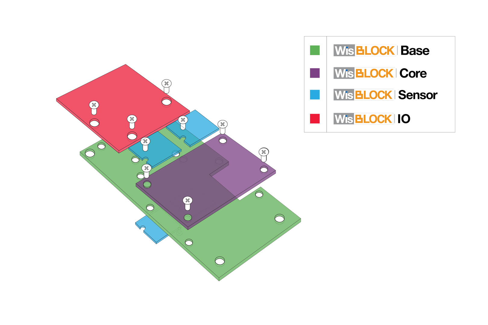 Figure 1: WisBlock-Assembly
Introduction
WisBlock is an amazing product built by RAK company for the IoT industry. It can build circuits like building blocks quickly to realize your idea, and through high-speed connectors and fasteners interconnection, it can directly compose reliable industrial products.
WisBlock consists of WisBlock Base, WisBlock Core, WisBlock Sensor, and WisBlock IO.
RAK5005-O is the WisBlock Base board which can be connected with WisBlock Core and WisBlock IO through the connector of the board and provides direct data bus interconnection. WisBlock Base module also integrates the power supply circuit to realize low power battery power supply. In order to facilitate users, WisBlock Base has reserved USB ports, indicator lights, keys, and extended IO interfaces.
RAK11200 is the WisBlock Core board which consists of ESP32 WROVER. It supports WiFi and BLE functions, and supply a rich resource MCU so that you can program it if you want.
WisBlock is not only a functional test capable product in the product development verification stage but also industrial products oriented to mass production. It uses a high-speed connector to ensure the integrity of the signal. At the same time, it is equipped with a fastening screw, which can be used in a vibration environment. And WisBlock can be used reliably in various civil and industrial scenarios through rigorous reliability tests.
WisBlock uses a compact stacked hardware design, which integrates various computing, connecting, and sensor circuits in the size of 60*30 mm. The compact size makes it easy for users to build in various customized housings to achieve complete products. RAK also has a series of housings for WisBlock modules, which can meet the requirements of various protection levels.
Safety Information
Read the following items carefully so that WisBlock can be used safely.
Hardware
- Use WisBlock according to its hardware specification, including the power supply, the temperature of use, the battery, and so on.
- Don't submerge WisBlock in liquids, and don't place WisBlock where water can reach.
- Don't power WisBlock using other power sources which RAK hasn't suggested.
- Some WisBlock modules require higher current that can't be provided by USB port alone. In this case, it is recommended to connect a battery to WisBlock Base Board.
- Battery can cause harm if not handled properly.
- Only 3.7-4.2 V Rechargeable LiPo batteries are supported. It is highly recommended not to use other types of batteries with the system unless you know what you are doing.
- If a non-rechargeable battery is used, it has to be unplugged first before connecting the USB cable to the USB port of the board to configure the device. Not doing so might damage the battery or cause a fire.x
- Make sure the battery wires match the polarity on the RAK WisBlock Base Board. Not all batteries have the same wiring.
- Only 5 V solar panels are supported. Do not use 12 V solar panels. It will destroy the charging unit and eventually other electronic parts.
-
There is already a bootloader in every WisBlock core board MCU when you receive the device so that you don't need to flash the bootloader again. Normally, you only need to use it directly or upload new code into it through Arduino IDE. If you accidentally erase the bootloader, contact RAK forum.
-
Don't unplug any hardware connector when you are uploading code into it, otherwise WisBlock may become unresponsive.
Hardware Setup
The RAK5005-O board offers several GPIO's on solder pads or the WisBlock Sensor or WisBlock IO modules. These GPIO's are named IO1 to IO6 and SW1. These GPIO's are connected to GPIO's of the RAK11200 module.
The GPIO assignments are defined in the RAK11200 variant.h file of the Arduino BSP.
RAK5005-O GPIO mapping to RAK11200 GPIO ports
| RAK5005-O GPIO port | RAK11200 GPIO port |
|---|---|
| RAK5005-O | ESP32 |
| IO1 | Arduino GPIO number 14 |
| IO2 | Arduino GPIO number 27 |
| IO3 | Arduino GPIO number 26 |
| IO4 | Arduino GPIO number 23 |
| IO5 | Arduino GPIO number 13 |
| IO6 | Arduino GPIO number 22 |
| SW1 | Arduino GPIO number 34 |
| A0 | Arduino GPIO number 36 |
| A1 | Arduino GPIO number 39 |
| SPI_CS | Arduino GPIO number 32 |
| LED1 | Arduino GPIO number 12 |
| LED2 | Arduino GPIO number 2 |
Defined names from variant.h
#define WB_IO1 14
#define WB_IO2 27
#define WB_IO3 26
#define WB_IO4 23
#define WB_IO5 13
#define WB_IO6 22
#define WB_SW1 34
#define WB_A0 36
#define WB_A1 39
#define WB_CS 32
#define WB_LED1 12
#define WB_LED2 2
Software Setup
Getting started with RAK11200 is simple and straightforward. The first thing you need is to set up your software development environment. We have made detailed tutorials on how to set up Arduino™ IDE and the PlatformIO extension to be ready to use the WisBlock 11200.
Arduino IDE BSP Installation
Install RAKWireless ESP32 BSP on Arduino Boards Manager
- To add board support for RAK11200 on Arduino, start Arduino IDE and open the Preferences window (File > Preferences).
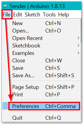 Figure 1: Arduino File Preferences Window
- In the Preferences window, look for Additional Boards Manager URLs and click the icon on the right side.
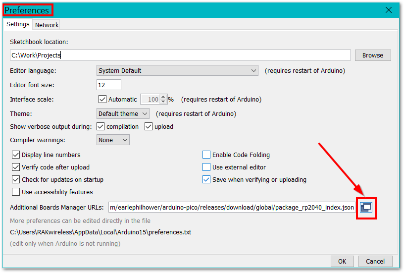 Figure 1: Arduino Preferences
- Copy
https://raw.githubusercontent.com/RAKwireless/RAKwireless-Arduino-BSP-Index/main/package_rakwireless_index.jsonand paste it into the new window.
- If there is already an URL from another manufacturer in that field, paste the above URL into a new line. Then press the OK button.
 Figure 1: Arduino Additional Boards Manager URLs
- Next, open the Boards Manager in the menu Tools.
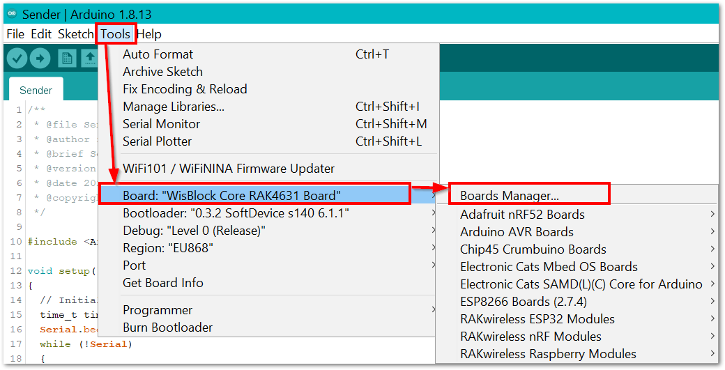 Figure 1: Arduino Boards Manager
- Type RAK in the search bar. The RAKwireless WisBlock Core modules will be shown in the window.
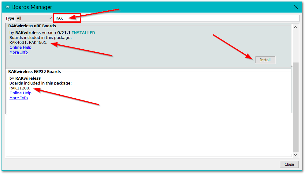 Figure 1: Arduino Tools Boards Manager
- Select RAKwireless ESP32 Boards and click on Install button.
Depending on your connection speed, the installation can take some time. Just be patient.
Compiling a Project
- The compiling process is very easy, what you need to do is just to click the Verify/Compile button on Arduino IDE.
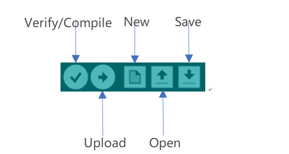 Figure 1: Arduino Verify/Compile
- After compiling successfully, you can see some information in the output message area, and the state is "Done compiling.":
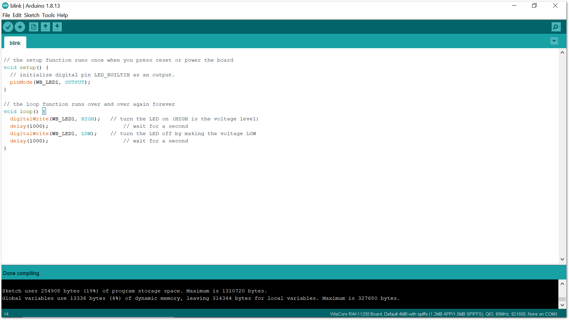 Figure 1: Arduino Done compiling
Now, you can connect your WisBlock hardware with your PC, and upload the code into it.
Uploading to WisBlock
Make sure that your WisBlock hardware has been connected with your PC correctly, and your PC has recognized WisBlock hardware successfully. If it is, you can select the board and port now, as shown in Figure 9:
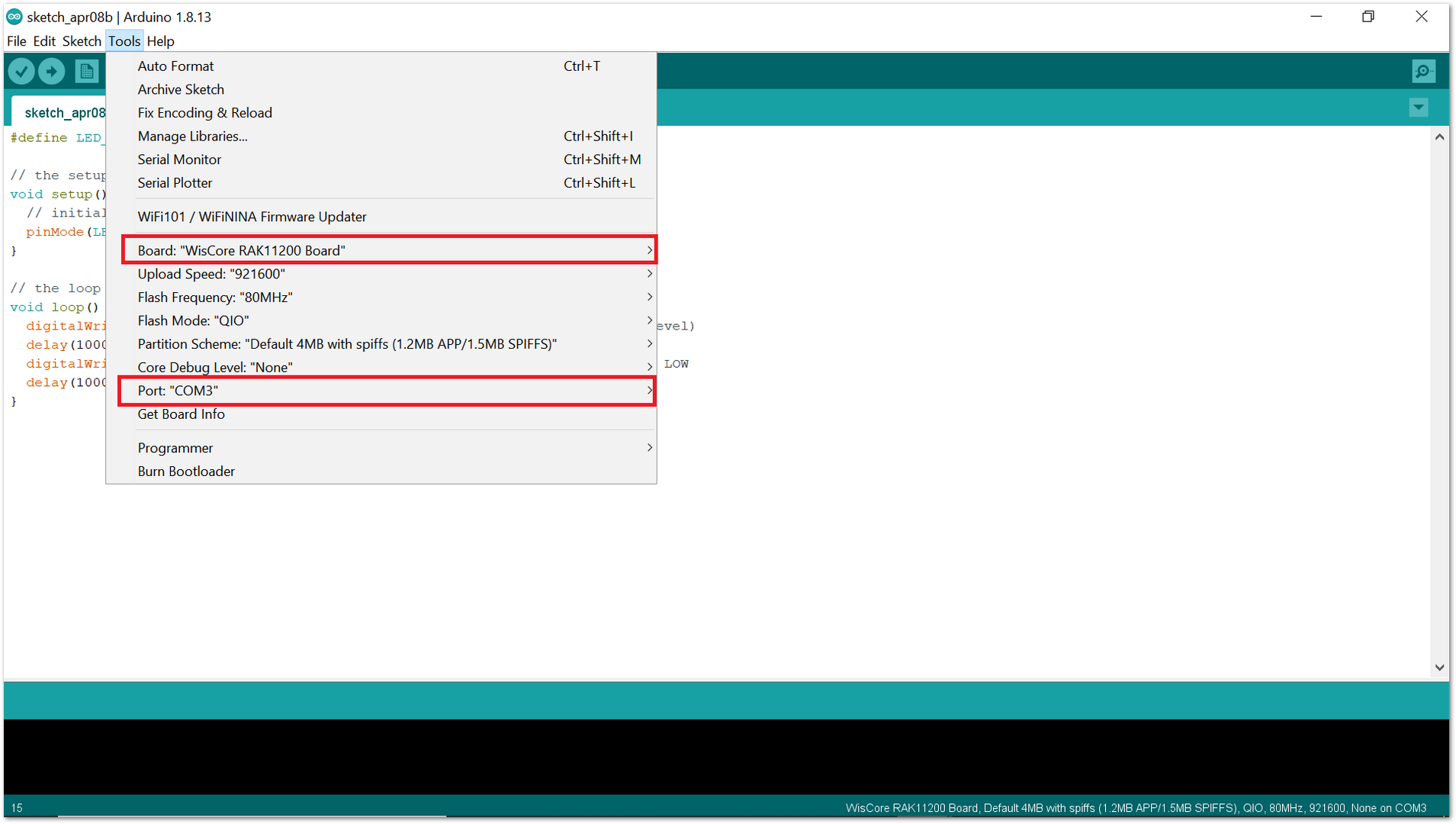 Figure 1: Arduino Tools Configuration
- Before uploading your sketch, short circuit BOOT0 and GND pin and press the reset button. Then click the Upload button using the configuration below.
Pin headers and jumpers are included on the RAK11200, which can be soldered to the WisBlock Base and help with BOOT0 pin accessibility.
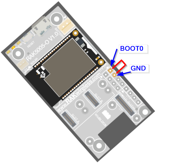 Figure 1: Force ESP32 Download mode
Board:"Wiscore RAK11200 board"
Upload Speed:"921600"
Flash Frequency:"80MHZ"
Flash Mode:"QIO"
Partition Scheme:"Default 4MB with spiffs(1.2MB APP/1.5MB SPIFFS)"
Core Debug Level:"No"
- After uploading successfully, push the reset button. Then you can see some information, as shown in Figure 11 in the output message area. That means you've uploaded the code into RAK11200 successfully.
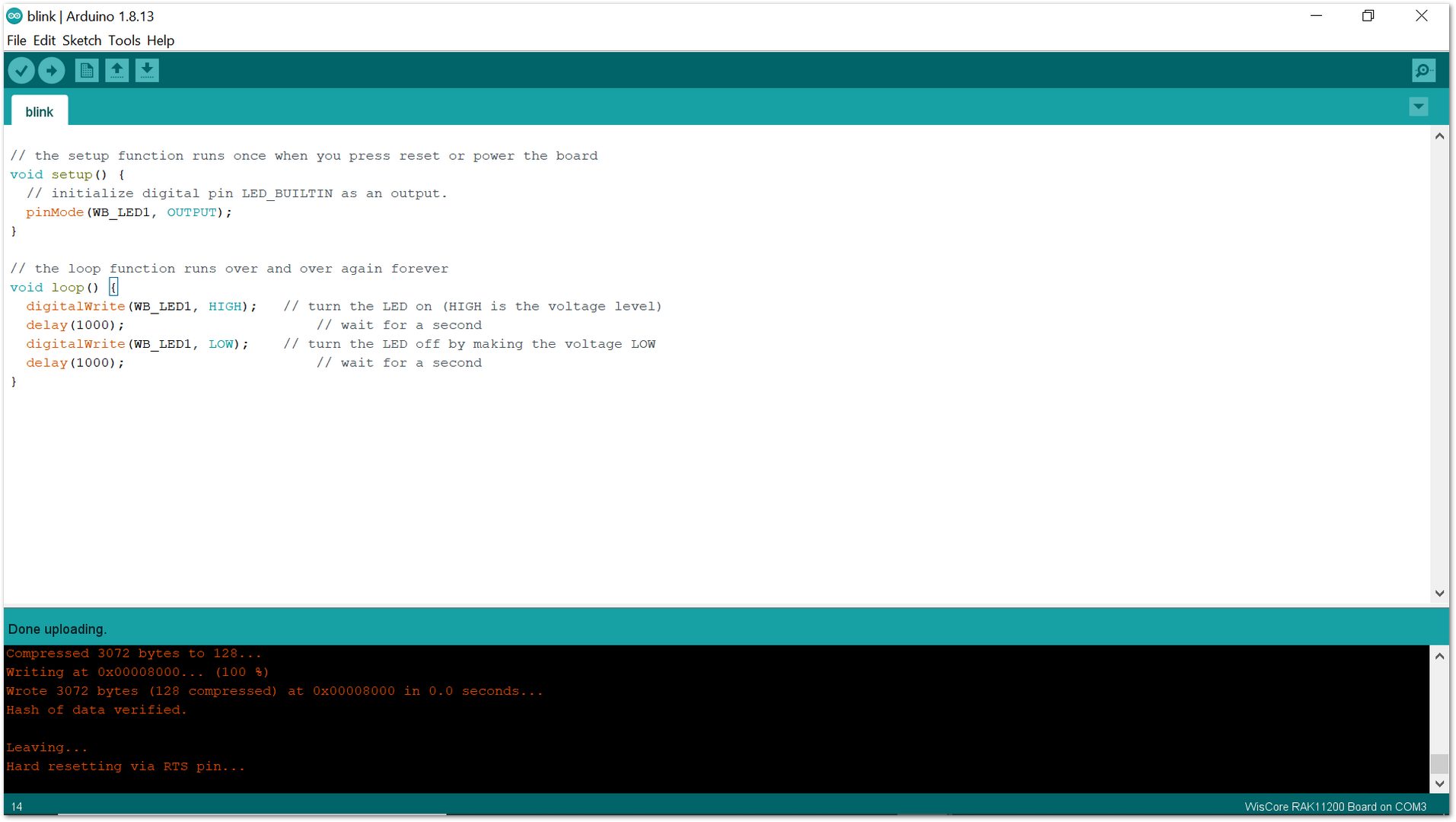 Figure 1: Arduino Done uploading
In case of upload error, the Upload Speed must be reduced.
Library Management on Arduino
In the Arduino IDE, the Library Manager and the libraries installed are available for every Arduino sketch.
Reserved GPIO Pins
It is not recommended to use the reserved GPIO pins. Some GPIO’s cannot be used freely, as they are already assigned to module peripherals or have special functions during booting.
Bootstraping Pins
-
GPIO0 pin is used as a bootstrapping pin and should be low to enter UART download mode. Make sure it is not pulled low by a peripheral device during boot or the firmware will not start.
-
GPIO2 pin is used as a bootstrapping pin, and should be low to enter UART download mode. Make sure it is not pulled high by a peripheral device during boot or you will not be able to flash a firmware to the module.
-
GPIO12 is used as a bootstrapping pin to select the output voltage of an internal regulator which powers the flash chip (VDD_SDIO). This pin has an internal pulldown so if left unconnected it will read low at reset (selecting default 3.3 V operation). Make sure it is not pulled high by a peripheral device during boot or the module might not be able to start.
-
GPIO15 can be used to stop debug output on Serial during boot. If pulled low, there will be no output on the Serial port during the boot process. This can be helpful in battery-powered applications where you do not want to use the Serial port at all to reduce power consumption.
SPI Flash Integrated Pins
GPIO06 to GPIO11 are connected to the integrated SPI flash on the ESP32-WROVER chip and are not recommended for other uses.
Input Only Pins
GPIO34-39 can only be set as input mode and do not have software pullup or pulldown functions.
PSRAM Pins
GPIO16 and 17 are used for the RAK11200 Pseudo static RAM (PSRAM).
ESP32 Basic Over The Air (OTA)
OTA stands for Over-The-Air. This feature allows uploading a new program to RAK11200 using WiFi instead of requiring the user to connect the RAK11200 to a computer via USB to perform the update. See the detailed instructions on the link below.
If you already installed the RAKwireless ESP32, then the BasicOTA sketch has also been installed.
- Open the Arduino IDE -> File -> Examples-> ArduinoOTA-> BasicOTA.
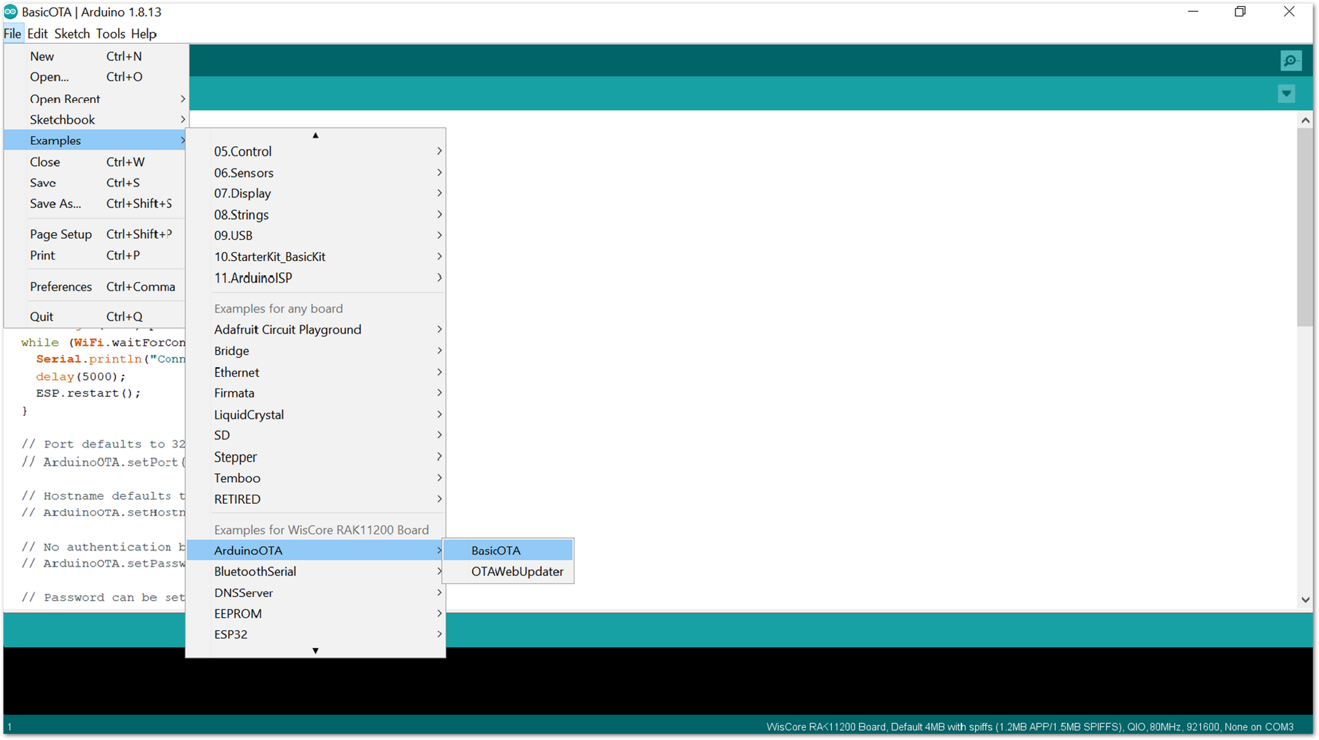 Figure 1: Arduino OTA Sketch
- Modify the following two variables with your network credentials, so that RAK11200 can establish a WiFi connection with the existing network. Then save and upload the BasicOTA sketch.
const char* ssid = "..........";
const char* password = "..........";
-
Now, upload a new sketch using over the air port.
-
Copy the blink LED sketch below to your Arduino IDE.
unsigned long previousMillis = 0;  // will store last time LED was updated
const long interval = 1000;  // interval at which to blink (milliseconds)
int ledState = LOW;  // ledState used to set the LED

void setup()
{
  pinMode(WB_LED1, OUTPUT);
}
void loop()
{

  //loop to blink without delay
  unsigned long currentMillis = millis();
  if (currentMillis - previousMillis >= interval) {
    // save the last time you blinked the LED
    previousMillis = currentMillis;
    // if the LED is off turn it on and vice-versa:
    ledState = not(ledState);
    // set the LED with the ledState of the variable:
    digitalWrite(WB_LED1,  ledState);
  }
}
The delay() for blinking builtin LED is not used because RAK11200 ESP32-WROVER pauses your program during the delay() routine. If the next OTA request is generated while the program is paused waiting for the delay() to pass, the OTA request will be lost.
- Open Arduino IDE and select Tools->Port->esp32-xxxx, as shown in Figure 13.
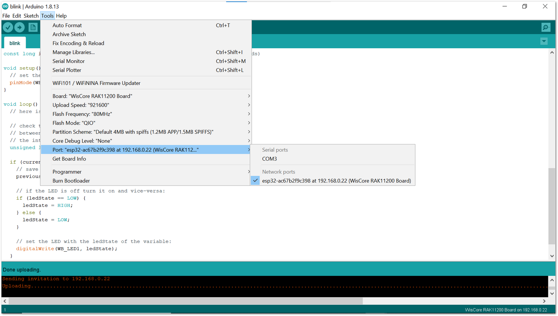 Figure 1: Arduino OTA WiFi Port
- Finally, click on Upload button.
Within a few seconds, the new sketch will be uploaded using over the air port.
ESP32 Deep Sleep
To achieve maximum power saving during deep sleep, it is necessary to switch off Bluetooth and WiFi before calling esp_deep_sleep_start().
#include <esp_wifi.h>
#include <esp_bt.h>
...
  esp_wifi_stop();
  esp_bt_controller_disable();
  esp_deep_sleep_start();
ESP32 Wiki Content
Installation of BSP in PlatformIO
Install PlatformIO
Download and install the Visual Studio Code which is a great and open source tool.
After installing the Visual Studio Code, you can search for PlatformIO and install it in the Extensions item.
Install Espressif 32 Arduino Framework
- After installing PlatformIO, you can see the PlatformIO icon and click open.
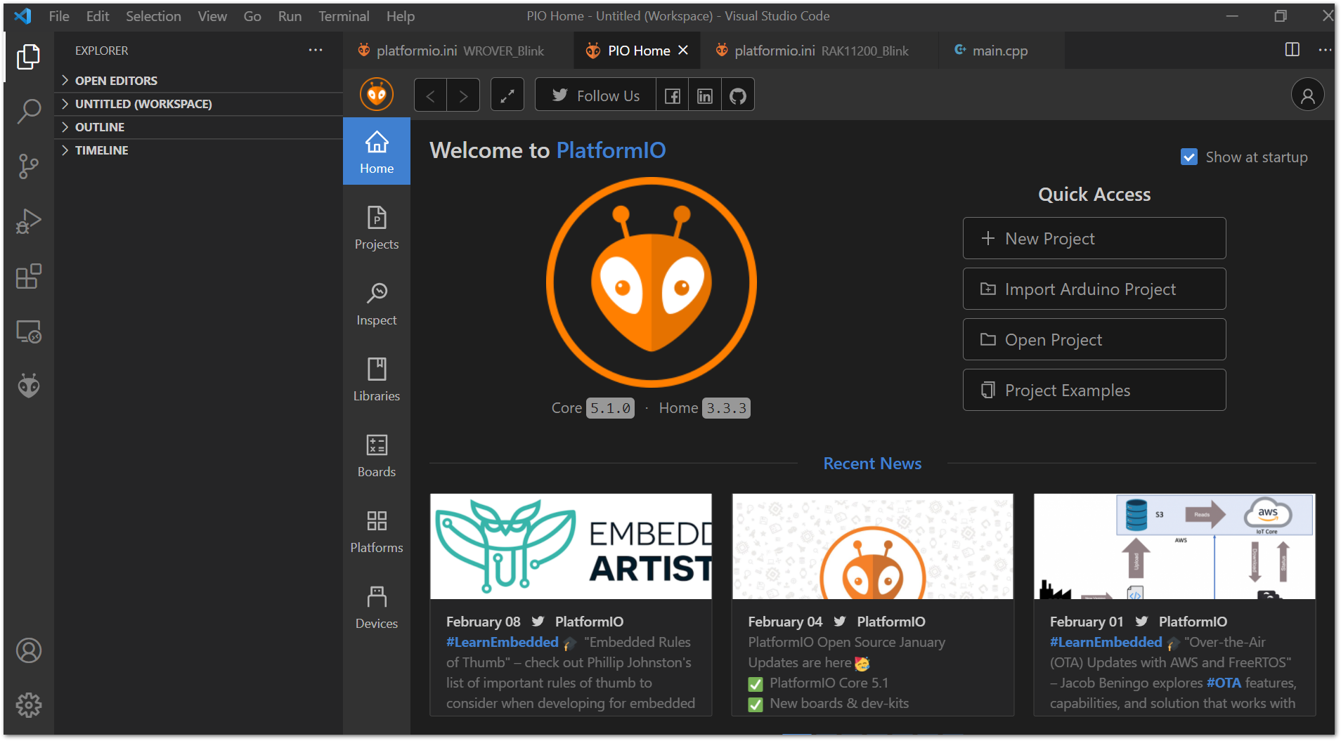 Figure 1: Visual Studio Code PlatformIO extension
- Open "Platforms" in PlatformIO and search for "Espressif" on Embedded tab.
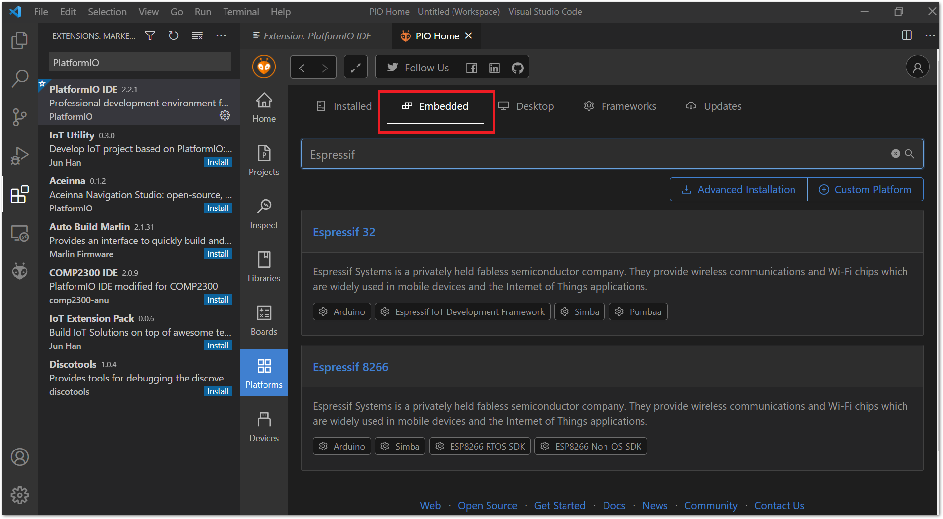 Figure 1: Espressif Platform
- You can see there are several items, just click "Espressif 32" item and then "Install".
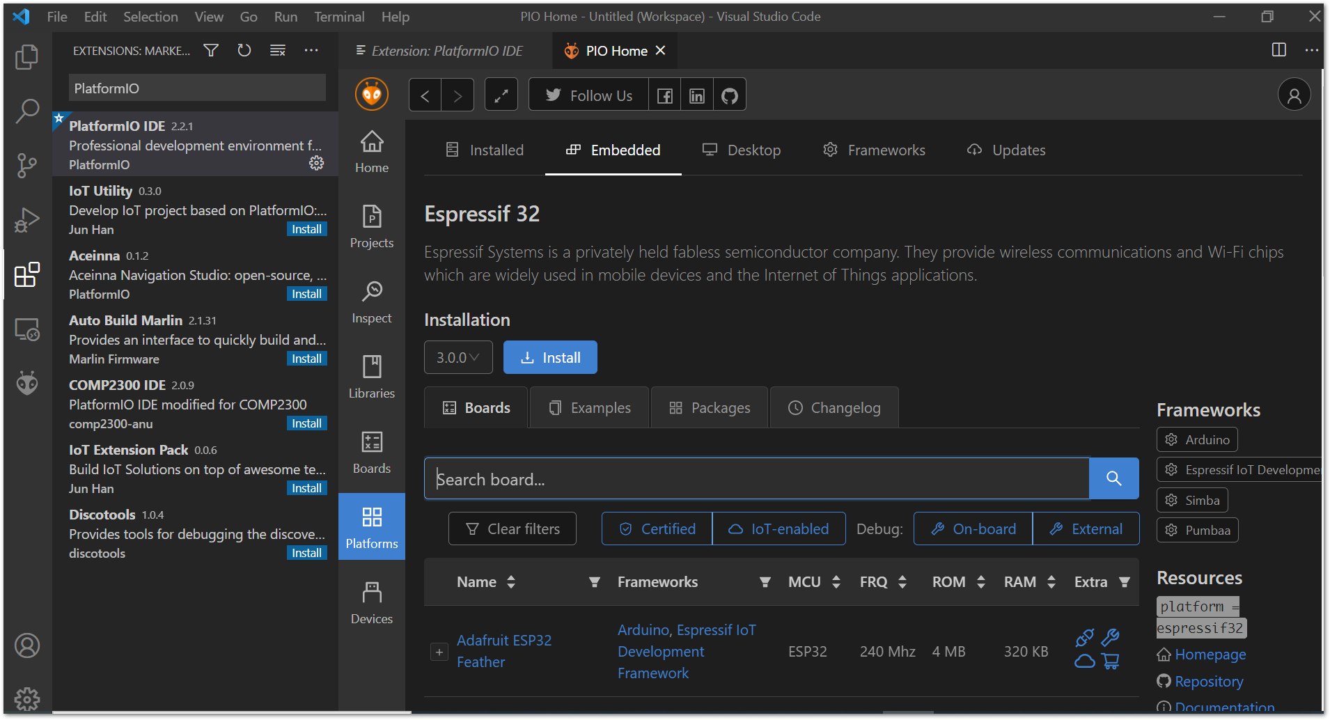 Figure 1: Espressif Framework
- Before running the first RAK11200 project on the PlatformIO, you need to ensure that the framework-arduinoespressif32 is installed. Then import a minimal project named arduino-blink. On PIO Home, click on "Project Examples".
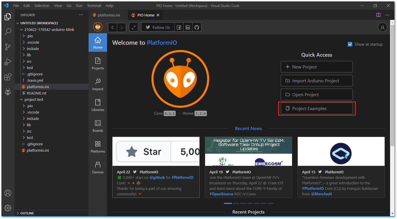 Figure 1: PIO Project Examples
- On "Import Project Example" window type arduino-blink and then click on Import button.
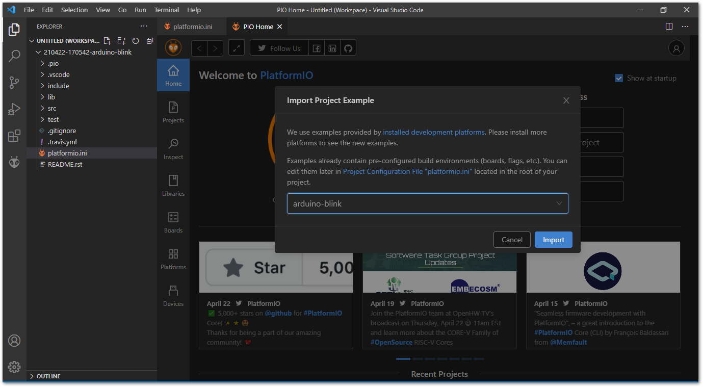 Figure 1: PIO arduino-blink
Add WisBlock Core RAK11200 to the Platform
- Clone WisBlock repository.
git clone https://github.com/RAKWireless/WisBlock.git
- Copy the file wiscore_rak11200.json located on folder cloned_dir\WisBlock\PlatformIO\RAK11200 to espressif32 platform folder.
-
The platform folder path is similar to the following:
- Windows: %userprofile%.platformio\platforms\espressif32\boards
- Linux (Ubuntu): $HOME/.platformio/platforms/espressif32/boards
- Mac OS: /Users/Your_User_id/.platformio/platforms/espressif32/boards
Add WisBlock Core RAK11200 to the Framework
Copy the folder WisCore_RAK11200_Board located on cloned_dir\WisBlock\PlatformIO\RAK11200 to the variants folder inside the espressif32 package folder.
-
The espressif32 package folder path is similar to the following:
- Windows: %userprofile%.platformio\packages\framework-arduinoespressif32\variants
- Linux (Ubuntu): $HOME/.platformio/packages/framework-arduinoespressif32/variants
- Mac OS: /Users/Your_User_id/.platformio/packages/framework-arduinoespressif32
Library Management on PlatformIO
The PlatformIO libraries are managed on a per-project basis. You install a library for a specific project and not for the entire IDE. Thus it is possible to have the same library working with different versions in two different projects.
