RAK12013 WisBlock Radar Sensor Module Datasheet
Overview
 Figure 1: RAK12013 WisBlock Radar Sensor
Description
RAK12013 is a 3.2GHz microwave radar module based on RCWL-9196. It uses the Doppler radar effect to detect moving objects/motion using microwaves. The RCWL-9196 will transmit and receive a 3GHz radar signal and compare the difference between the two signals to determine whether the object is moving or not.
- Radar signals don't interfere with other signals such as LoRa, WiFi, and Bluetooth; but multiple radar signals interfere with each other between single individuals over a distance greater than 1 meter.
- The component side of the PCB module or the front is the positive sensing face, while the opposite side which is the back is the negative sensing face. The negative sensing face is less effective in terms of sensing.
Features
- 3.3 V Power Supply
- Current Consumption: < 3 uA
- Chipset: RCWL RCWL-9196
- Motion Detection Module
- Detection Distance: 5 - 7 meters
- Detection Area: 360 degrees angle with no blind spot
- Frequency: 3.2 GHz
- Trigger Way: repeat trigger
- Module size: 25 x 35 mm
Specifications
Overview
Mounting
The RAK12013 WisBlock Radar Sensor Module can be mounted to the IO slot of the WisBlock Base board. Figure 2 shows the mounting mechanism of the RAK12013 on a WisBlock Base module.
 Figure 1: RAK12013 Mounting Mechanism on a WisBlock Base Module
Hardware
The hardware specification is categorized into five (5) parts. It shows the chipset of the module and discusses the pinouts and their corresponding functions and diagrams. It also covers the electrical and mechanical characteristics that include the tabular data of the functionalities and standard values of the RAK12013 WisBlock Radar Sensor Module.
Chipset
| Vendor | Part number |
|---|---|
| RCWL | RCWL-9196 |
Pin Definition
The RAK12013 module has a 40-pin WisConnector that is compatible to the WisBlock Base IO Slot. The pin order of the connector and the pinout definition is shown in Figure 3.
 Figure 1: RAK12013 Pinout Diagram
- Only OUT, EN, 3V3_S, and GND are connected to the WisConnector.
- EN is used to enable the module.
- OUT is the output signal from the module.
- 3V3_S voltage output from the WisBlock Base that powers the RAK12013 module can be controlled by the WisBlock Core via WB_IO2 (WisBlock IO2 pin). This makes the module ideal for low-power IoT projects since the WisBlock Core can totally disconnect the power of the RAK12013 module.
Electrical Characteristics
This section shows the maximum and minimum ratings of the RAK12013 module and its recommended operating conditions. Refer to the table presented below.
Absolute Maximum Ratings
| Parameter | Minimum | Maximum | Unit |
|---|---|---|---|
| 3V3_S | -0.3 | 4.7 | V |
Power Supply Ratings
| Symbol | Description | Condition | Min. | Nom. | Max. | Unit |
|---|---|---|---|---|---|---|
| VDD | Supply voltage | Input voltage must within this range | 2.2 | 3.3 | 4.7 | V |
| IDD | Supply current | Normal | - | 2.8 | 3 | uA |
| Power | Transmitting Power | Transmitting Power | - | 20 | 30 | mW |
Mechanical Characteristics
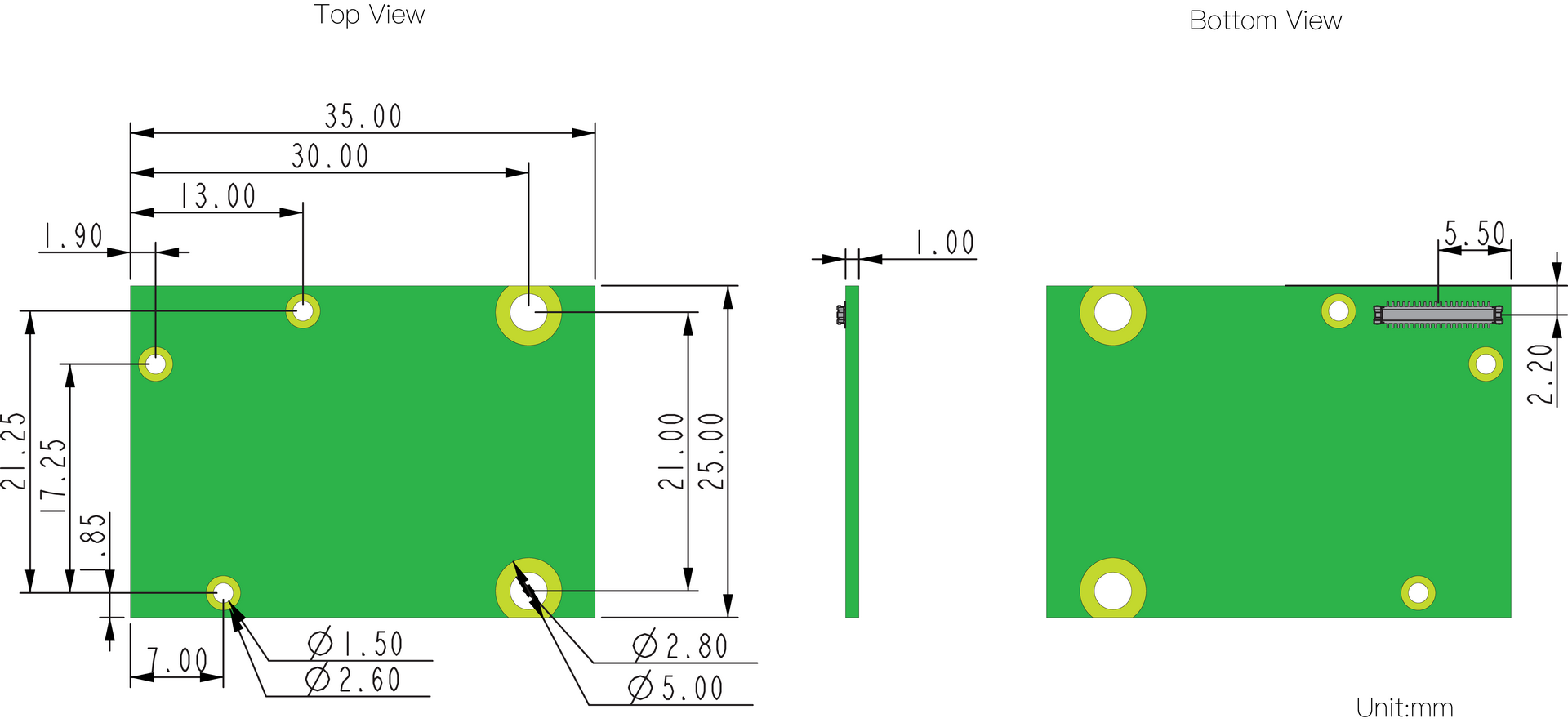
Board Dimensions
Figure 4 shows the mechanical dimensions of the RAK12013 Module.
 Figure 1: RAK12013 Mechanical Dimensions
WisConnector PCB Layout
 Figure 1: WisConnector PCB Footprint and Recommendations
Schematic Diagram
Figure 6 shows the schematic of the RAK12013 module.
 Figure 1: RAK12013 WisBlock Module Schematics
Boost Converter
The RCWL-9196 operating voltage is 4 V - 24 V. So, you need to boost it from 3.3 V to 5 V.
 Figure 1: Boost Converter
RCWL-9196
- Pin 1 is used for Mode Select, and R8 is used as default:
- Mode 0: Non-retriggerable
- Mode 1: Retriggerable
- C-TM: Adjust repeat trigger time (default 2s). To make the trigger repeat time longer, add a capacitor to the solder points of C-TM, and the actual counting trigger time can operate as follows:
- Stick capacitor on C-TM, test 9196 3-pin frequency (F), and repeat trigger time T=(1/f)*32768.
- R-GN: Detection distance adjustment. Connect with a resistor, and the detection distance will become shorter. If no resistor is connected, the default detection distance is 7 meters. If it is connected with a 1 MΩ resistor, the detection distance will become 5 meters. R7 is NC as default.
 Figure 1: RCWL-9196
Antenna
 Figure 1: Antenna