RAK12015 WisBlock Vibration Detection Sensor Module Quick Start Guide
Prerequisite
What Do You Need?
Before going through each and every step on using the RAK12015 WisBlock Vibration Detection Sensor Module, make sure to prepare the necessary items listed below:
Hardware
- RAK12015 WisBlock Vibration Detection Sensor Module
- Your choice of WisBlock Base with IO slot
- Your choice of WisBlock Core
- USB Cable
- RAK19008 WisBlock IO Extension Cable (optional)
- Li-Ion/LiPo battery (optional)
- Solar charger (optional)
Software
- Download and install ArduinoIDE.
- To add the RAKwireless Core boards on your Arduino Boards Manager, install the RAKwireless Arduino BSP.
Product Configuration
Hardware Setup
The RAK12015, a part of WisBlock Sensor, is a Vibration Detection Module that uses a high-precision sensor, the ANT-801S. This sensor is capable of detecting micro shocks or vibration without direction limits. For more information about RAK12015, refer to the Datasheet.
RAK12015 module can be connected to the IO slot of WisBlock Base to communicate with the WisBlock Core, as shown in Figure 1. Also, always secure the connection of the WisBlock module by using compatible screws.
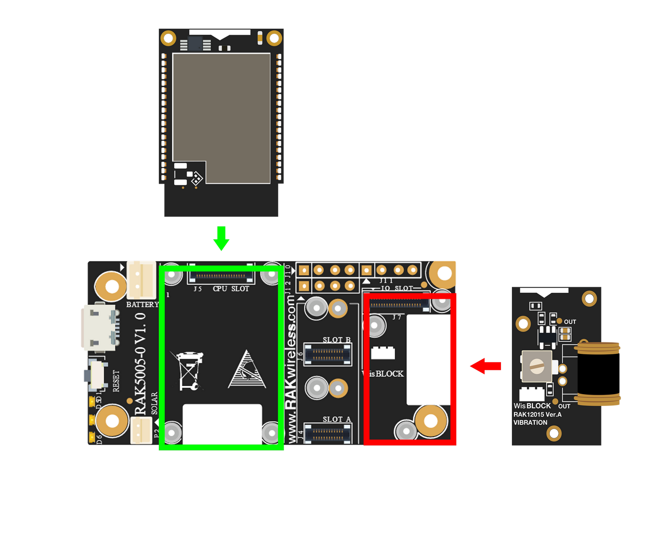 Figure 1: RAK12015 Connection to WisBlock Base
Assembling and Disassembling of WisBlock Modules
Assembling
As shown in Figure 2, the location for the IO slot is properly marked by silkscreen. Follow carefully the procedure defined in WisBlock Base board assembly/disassembly instructions to attach a WisBlock module. Once attached, carefully fix the module with three pieces of M1.2 x 3 mm screws.
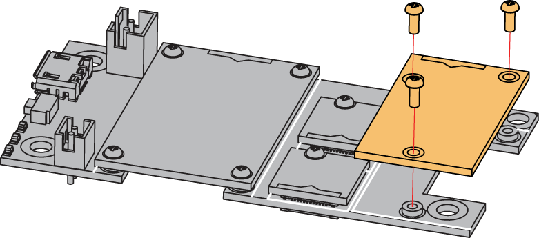 Figure 1: RAK12015 assembly to WisBlock Base
Disassembling
The procedure in disassembling any type of WisBlock modules is the same.
- First, remove the screws.
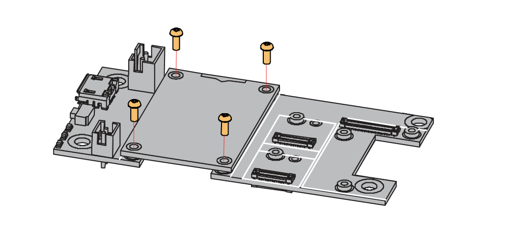 Figure 1: Removing screws from the WisBlock module
- Once the screws are removed, check the silkscreen of the module to find the correct location where force can be applied.
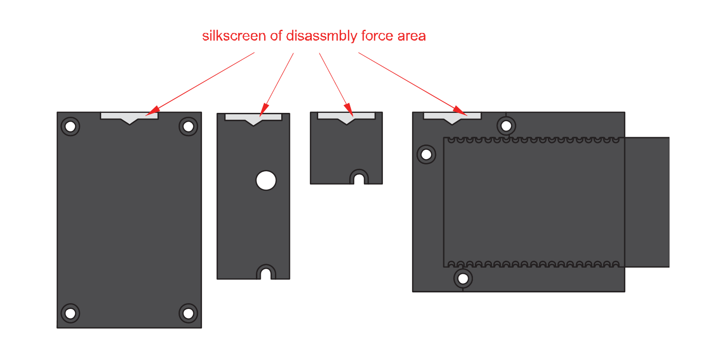 Figure 1: Detaching silkscreen on the WisBlock module
- Apply force to the module at the position of the connector, as shown in Figure 5, to detach the module from the baseboard.
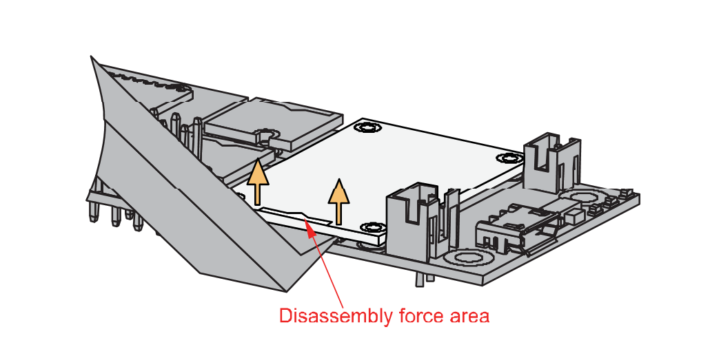 Figure 1: Applying even forces on the proper location of a WisBlock module
If you will connect other modules to the remaining WisBlock Base slots, check on the WisBlock Pin Mapper tool for possible conflicts.
After all this setup, you can now connect the battery (optional) and USB cable to start programming your WisBlock Core.
- Batteries can cause harm if not handled properly.
- Only 3.7-4.2 V Rechargeable LiPo batteries are supported. It is highly recommended not to use other types of batteries with the system unless you know what you are doing.
- If a non-rechargeable battery is used, it has to be unplugged first before connecting the USB cable to the USB port of the board to configure the device. Not doing so might damage the battery or cause a fire.
- Only 5 V solar panels are supported. Do not use 12 V solar panels. It will destroy the charging unit and eventually other electronic parts.
- Make sure the battery wires match the polarity on the WisBlock Base board. Not all batteries have the same wiring.
Software Configuration and Example
In this example, you will monitor if this sensor is triggered by nearby vibrations.
-
Install the RAKwireless Arduino BSP's for WisBlock by using the
package_rakwireless_index.jsonboard installation package, the WisBlock Core should now be available on the Arduino IDE. -
You need to select first the WisBlock Core you have, as shown in Figure 6 to Figure 8.
RAK4631 Board
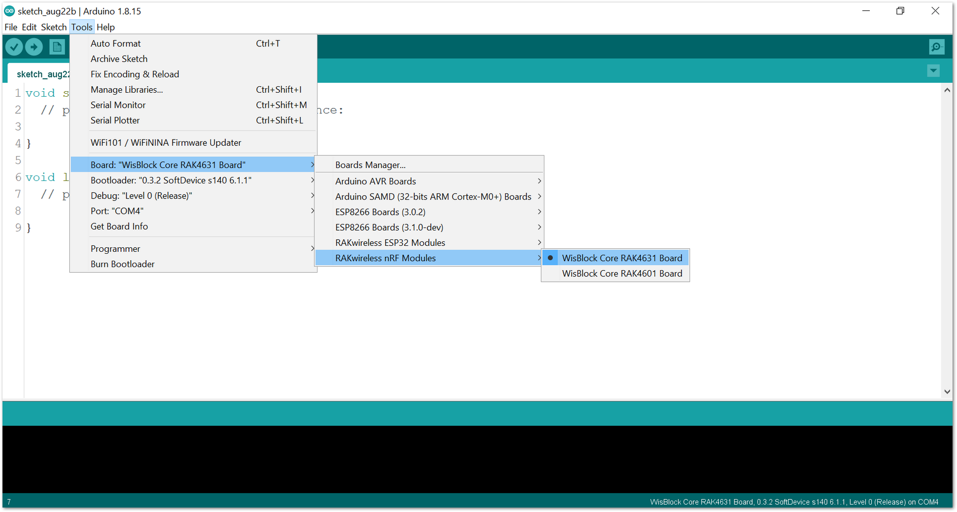 Figure 1: Selecting RAK4631 as WisBlock Core
RAK11200 Board
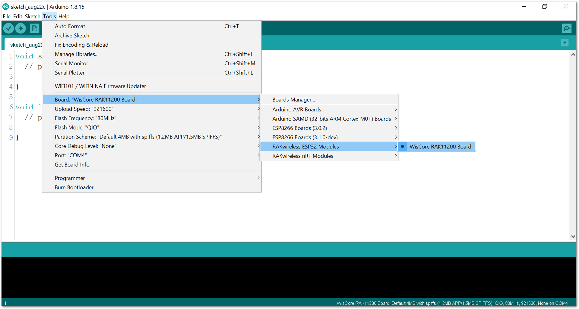 Figure 1: Selecting RAK11200 as WisBlock Core
RAK11310 Board
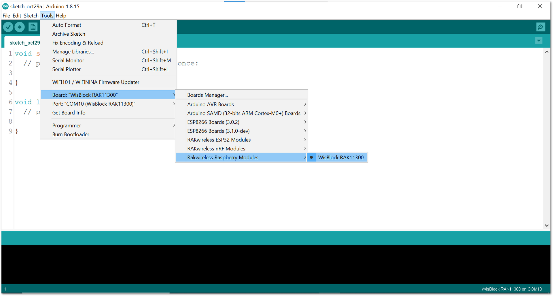 Figure 1: Selecting RAK11300 as WisBlock Core
- Copy the example code below:
Click to view the code
/**
   @file RAK12015_Shock_801S.ino
   @author rakwireless.com
   @brief Setup and read values from a 801S sensor
   @version 0.1
   @date 2021-07-23
   @copyright Copyright (c) 2021
**/

#include <Arduino.h>
#include "Wire.h"
#define SensorOutput   WB_A1
uint8_t interrupt1Flag = 0;

void setup() {
  // put your setup code here, to run once:
  time_t timeout = millis();
  Serial.begin(115200);
  /* WisBLOCK 12015 Power On*/
  pinMode(WB_IO2, OUTPUT);
  digitalWrite(WB_IO2, HIGH);
  delay(300);
  /* WisBLOCK 12015 Power On*/
  while (!Serial)
  {
    if ((millis() - timeout) < 5000)
    {
      delay(100);
    }
    else
    {
      break;
    }
  }
  //falling edge fires , triggers interrupt a1, and calls the interrupt flag function
  pinMode(SensorOutput, INPUT);
  attachInterrupt(SensorOutput, interruptHandle1, RISING);
  Serial.println("RAK12015 test Example");
}


/*
 * brief:The threshold of the sensor is determined by the resistance of the pull-up resistor.
 * Now the pull-up resistance is 10K
 */
void loop() {
  // put your main code here, to run repeatedly:
  if (interrupt1Flag == 1)
  {
    Serial.println("Trigger vibration sensor");
    interrupt1Flag=0;
  }
  delay(500);
}

void interruptHandle1(void)
{
  interrupt1Flag = 1;
}
If you experience any error in compiling the example sketch, check the updated code for the RAK12015 WisBlock Vibration Detection Sensor Module that can be found on the RAK12015 WisBlock Example Code Repository
- Then select the right Serial Port and upload the code, as shown in Figure 9 and Figure 10.
If you are using the RAK11200 as your WisBlock Core, the RAK11200 requires the Boot0 pin to be configured properly first before uploading. If not done properly, uploading the source code to RAK11200 will fail. Check the full details on the RAK11200 Quick Start Guide.
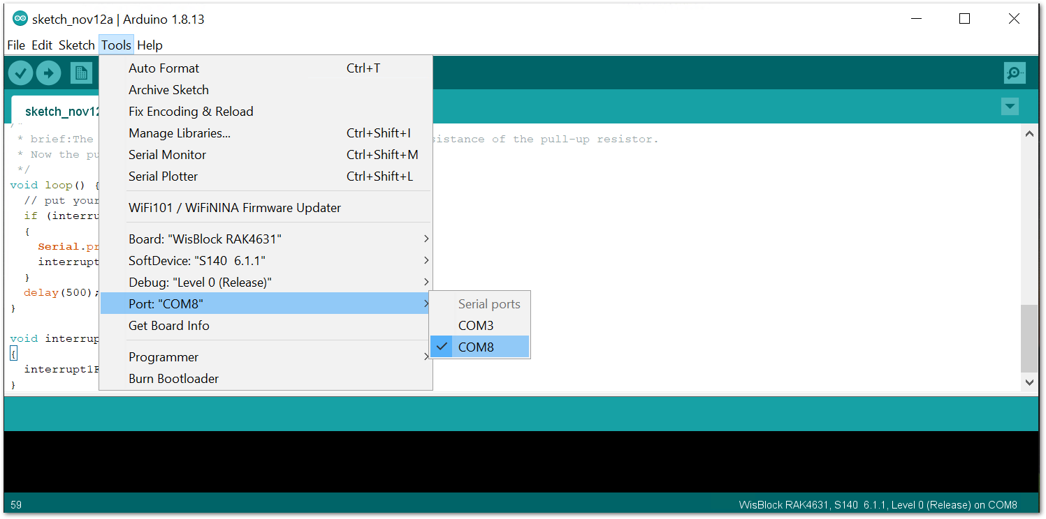 Figure 1: Selecting the correct Serial Port
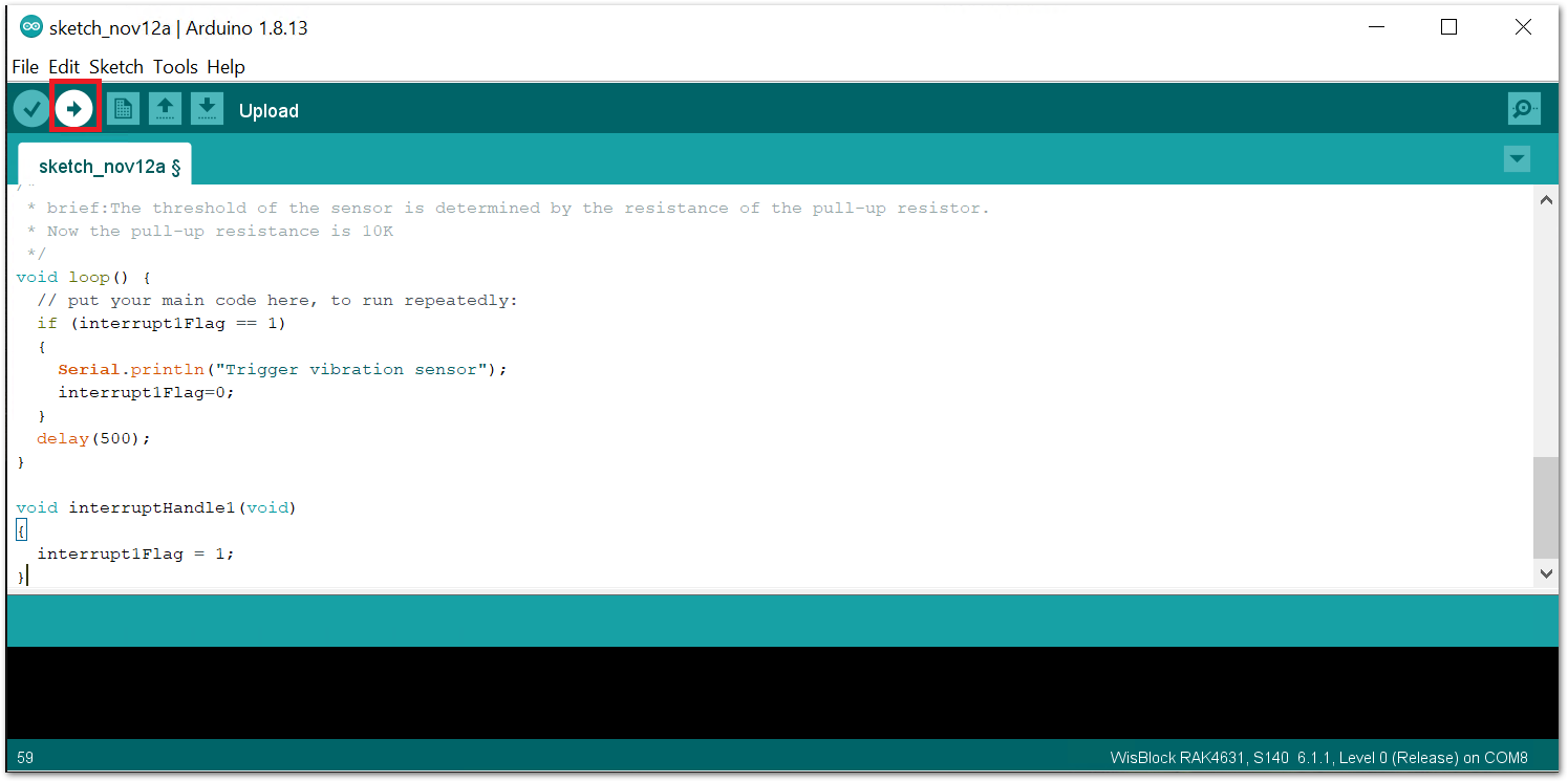 Figure 1: Uploading the sample code
- When you have successfully uploaded the sample code, lay the module flat on the table and hit or stomp the table, as shown in Figure 11. Then, you can open up your serial monitor to get the sensor reading, as shown in Figure 12.
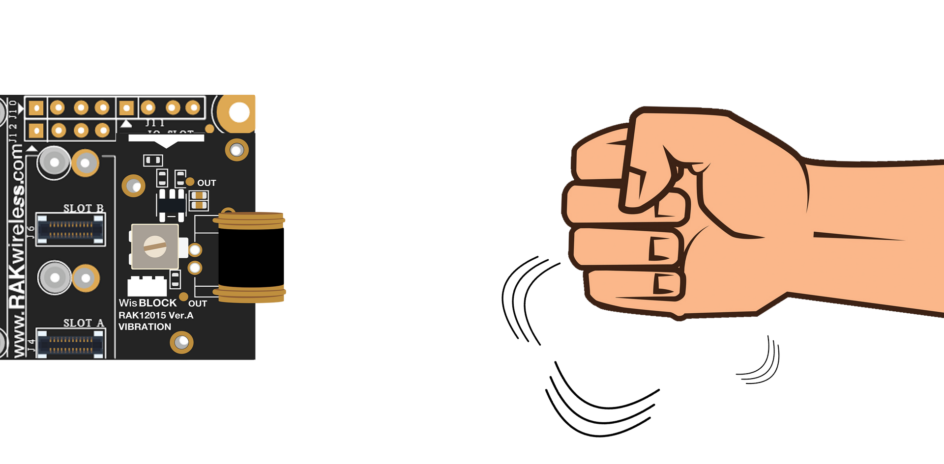 Figure 1: Hitting the desk or table to create vibrations
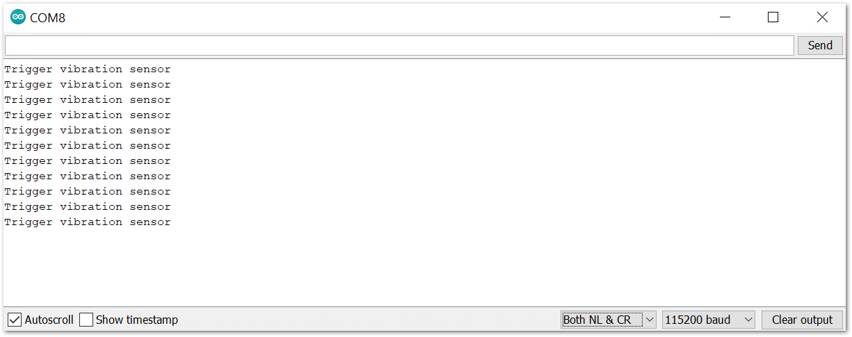 Figure 1: Triggered sensor reading in Serial Monitor