RAK12016 WisBlock Flex Sensor Module Quick Start Guide
Prerequisite
What Do You Need?
Before going through each and every step on using the RAK12016 WisBlock module, make sure to prepare the necessary items listed below:
Hardware
- RAK12016 WisBlock Flex Sensor Module
- Your choice of WisBlock Base with IO slot
- Your choice of WisBlock Core
- USB Cable
- Li-Ion/LiPo battery (optional)
- Solar charger (optional)
Software
- Download and install the ArduinoIDE.
- To add the RAKwireless Core boards on your Arduino board, install the RAKwireless Arduino BSP. Follow the steps in the Github repo.
Product Configuration
Hardware Setup
RAK12016 is a flex sensor module, a part of the RAKwireless WisBlock Sensor series. It uses an FS-L-0095-103-ST from Spectrasymbol, which can measure the amount of deflection or bending.
For more information about RAK12016, refer to the Datasheet.
RAK12016 module can be connected to the IO slot of WisBlock Base to communicate with the WisBlock Core, as shown in Figure 1. Also, always secure the connection of the WisBlock module by using compatible screws.
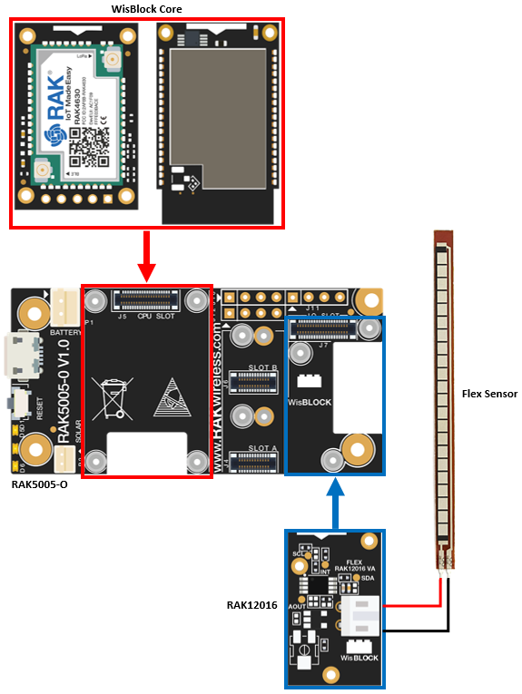 Figure 1: RAK12016 connection to WisBlock Base
Flex Sensor
A flex sensor uses carbon on a strip of plastic, which acts as a variable resistor. The more it bends, the higher the resistance of the sensor increases.
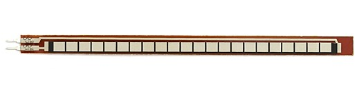 Figure 1: FS-L-0095-103-ST Flex Sensor
The Flex sensor can only be bent in one direction. Thus, bending the sensor in the other direction may not produce any reliable data and may damage the sensor. Also, be careful not to bend the flex sensor near the bottom where the wires are attached in the RAK12016 module, as they have the potential to kink and fail.
Assembling and Disassembling of WisBlock Modules
Assembling
As shown in Figure 3, the location for the IO slot is properly marked by silkscreen. Follow carefully the procedure defined in WisBlock Base board assembly/disassembly instructions to attach a WisBlock module. Once attached, carefully fix the module with three pieces of M1.2 x 3 mm screws.
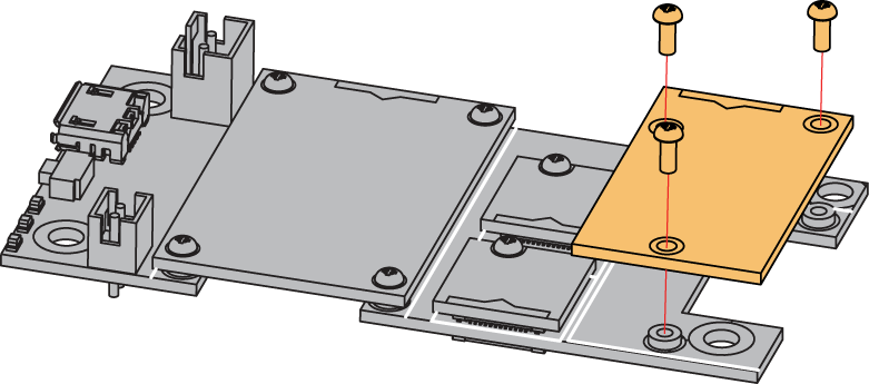 Figure 1: RAK12016 mounting connection to WisBlock Base module
Disassembling
The procedure in disassembling any type of WisBlock modules is the same.
- First, remove the screws.
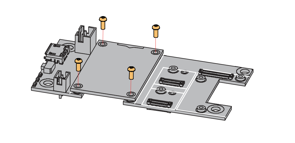 Figure 1: Removing screws from the WisBlock module
- Once the screws are removed, check the silkscreen of the module to find the correct location where force can be applied.
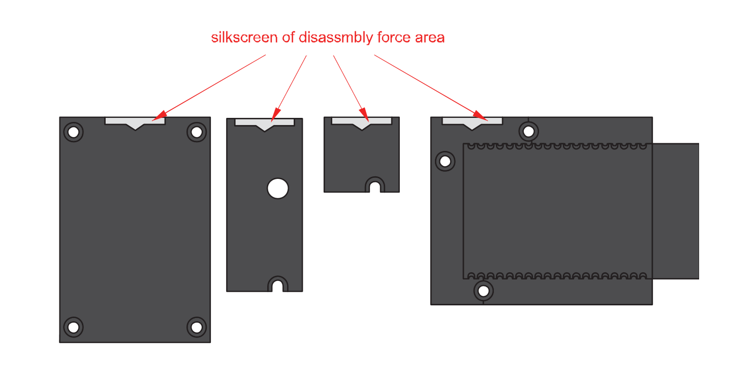 Figure 1: Detaching silkscreen on the WisBlock module
- Apply force to the module at the position of the connector, as shown in Figure 6, to detach the module from the base board.
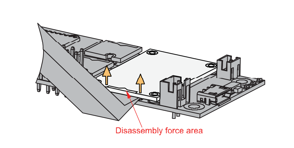 Figure 1: Applying even forces on the proper location of a WisBlock module
If you will connect other modules to the remaining WisBlock Base slots, check on the WisBlock Pin Mapper tool for possible conflicts.
After all this setup, you can now connect the battery (optional) and USB cable to start programming your WisBlock Core.
- Batteries can cause harm if not handled properly.
- Only 3.7-4.2 V Rechargeable LiPo batteries are supported. It is highly recommended not to use other types of batteries with the system unless you know what you are doing.
- If a non-rechargeable battery is used, it has to be unplugged first before connecting the USB cable to the USB port of the board to configure the device. Not doing so might damage the battery or cause a fire.
- Only 5 V solar panels are supported. Do not use 12 V solar panels. It will destroy the charging unit and eventually other electronic parts.
- Make sure the battery wires match the polarity on the WisBlock Base board. Not all batteries have the same wiring.
Software Configuration and Example
Initial Test of the RAK12016 WisBlock Module
-
Install the RAKwireless Arduino BSP for WisBlock by using the
package_rakwireless_index.jsonboard installation package. The WisBlock Core should now be available on the Arduino IDE. -
You need to select first the WisBlock Core you have.
RAK4631 Board
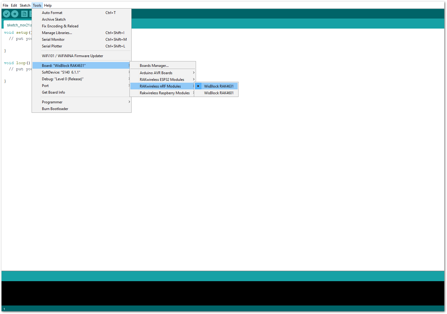 Figure 1: Selecting RAK4631 as WisBlock Core
RAK11200 Board
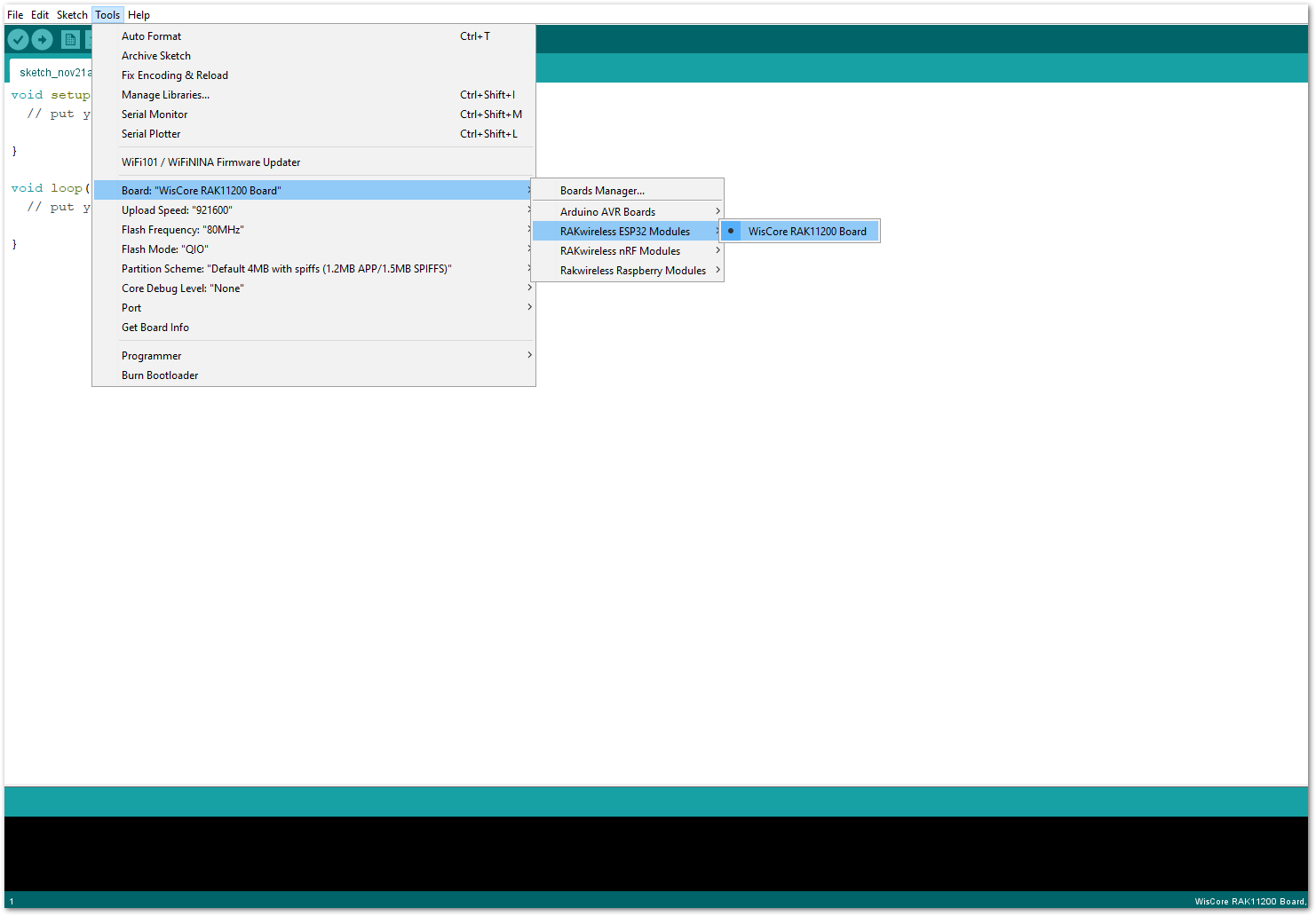 Figure 1: Selecting RAK11200 as WisBlock Core
RAK11310 Board
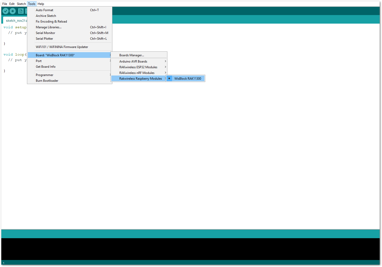 Figure 1: Selecting RAK11310 as WisBlock Core
- Next, copy the following sample code into your Arduino IDE:
Click to view the code
/**
   @file RAK12016_Flex_FSL0095103ST.ino
   @author rakwireless.com
   @brief use Flex sensor read sensor datas example.
   @version 0.1
   @date 2021-07-26
   @copyright Copyright (c) 2021
*/

#include <Wire.h>
#include "ADC121C021.h"    // Click here to get the library: http://librarymanager/All#RAKwireless_MQx_library
#define  ReferenceVoltage  3.3
#define  FLEX_ADDRESS      0x54    //the device i2c address

// Measure the voltage at 3.3V and the actual resistance of your// 10k resistor, and enter them below:
const float VCC = 3.3;                       //Module supply voltage, ADC reference voltage is 3.3V
const float R_DIV = 10000.0;                 // The partial voltage resistance is 10KΩ
// Upload the code, then try to adjust these values to more// accurately calculate bend degree.
const float STRAIGHT_RESISTANCE = 11563.0;   // The flat Resistance
const float BEND_RESISTANCE = 21117.0;      //Resistance at 90 degree bending
ADC121C021 Flex;
void setup() {
  // put your setup code here, to run once:
  /* WisBLOCK 12016 Power On*/
  pinMode(WB_IO2, OUTPUT);
  digitalWrite(WB_IO2, HIGH);
  delay(300);
  /* WisBLOCK 12016 Power On*/
  time_t timeout = millis();
  Serial.begin(115200);
  while (!Serial)
  {
    if ((millis() - timeout) < 5000)
    {
      delay(100);
    }
    else
    {
      break;
    }
  }

  //********ADC121C021 ADC convert init ********************************
  while (!(Flex.begin(FLEX_ADDRESS, Wire)))
  {
    Serial.println("please check device!!!");
    delay(200);
  }

  Flex.setVoltageResolution(ReferenceVoltage);
  float flexRef = Flex.getVoltageResolution();
  uint8_t flexflag = abs(flexRef - ReferenceVoltage);
  while(flexflag)
  {
    Serial.println("please check the Reference Voltage!!!");
    delay(200);
  }
  Serial.println("RAK12016 test Example");
}

/*
 * Step 1: Connect the Flex sensor to the sensor module, supply power VCC (3.3V) to the module
 * Step 2: Open serial debugging assistant (baud rate 115200), you can see the current printed resistance value. Record the resistance value (unit Ω) at the level and maximum bending to be measured respectively.
 * Step 3: Rerunned the test routine after correcting the values of STRAIGHT_RESISTANCE and BEND_RESISTANCE both horizontal resistance variables
 * Step 4: The Flex sensor can only be bent to one side of the print. Bending the sensor in the other direction does not produce any reliable data and may damage the sensor,Also be careful not to bend the sensors near the bottom, as they have the potential to kink and fail
 */

void loop() {
  // put your main code here, to run repeatedly:
  float flexVoltage = Flex.getSensorVoltage();
  float flexR = R_DIV * (VCC / flexVoltage - 1.0);
  Serial.println("Voltage: " + String(flexVoltage) + " V");
  Serial.println("Resistance: " + String(flexR) + " ohms");
  float angle = map(flexR, STRAIGHT_RESISTANCE, BEND_RESISTANCE, 0, 90.0);
  Serial.println("Bend: " + String(angle) + " degrees");
  Serial.println();
  delay(500);
}
If you experience any error in compiling the example sketch, check the updated code for your WisBlock Core Module that can be found on the RAK12016 WisBlock Example Code Repository. This sample code in Github will work on all WisBlock Core.
- Once the example code is open, install the RAKWireless MQx library by clicking the yellow highlighted link, as shown in Figure 10 and Figure 11.
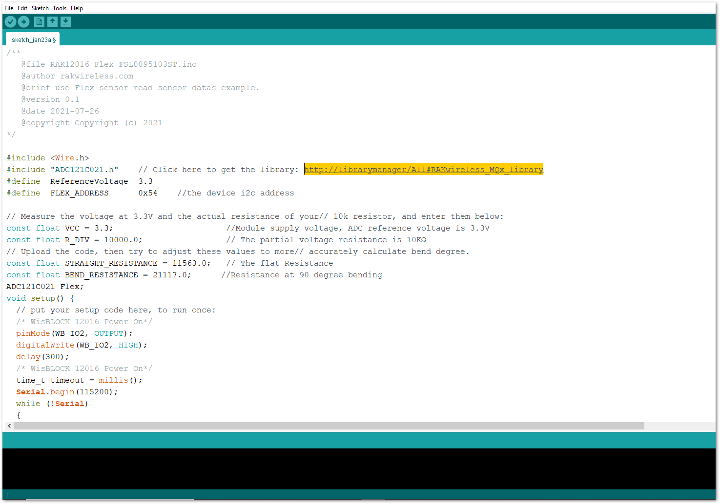 Figure 1: Accessing the library used for RAK12016 Module
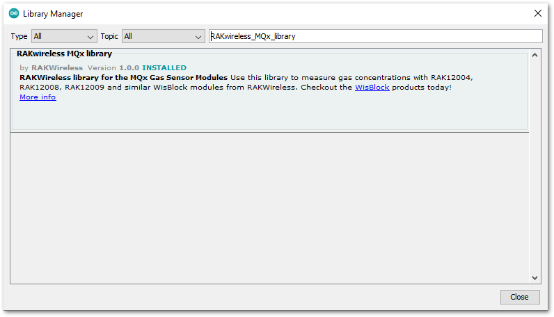 Figure 1: Installing the compatible library for RAK12016 Module
- After successful installation of the library, you can now select the right serial port and upload the code, as shown in Figure 12 and Figure 13.
If you are using the RAK11200 as your WisBlock Core, the RAK11200 requires the Boot0 pin to be configured properly first before uploading. If not done properly, uploading the source code to RAK11200 will fail. Check the full details on the RAK11200 Quick Start Guide.
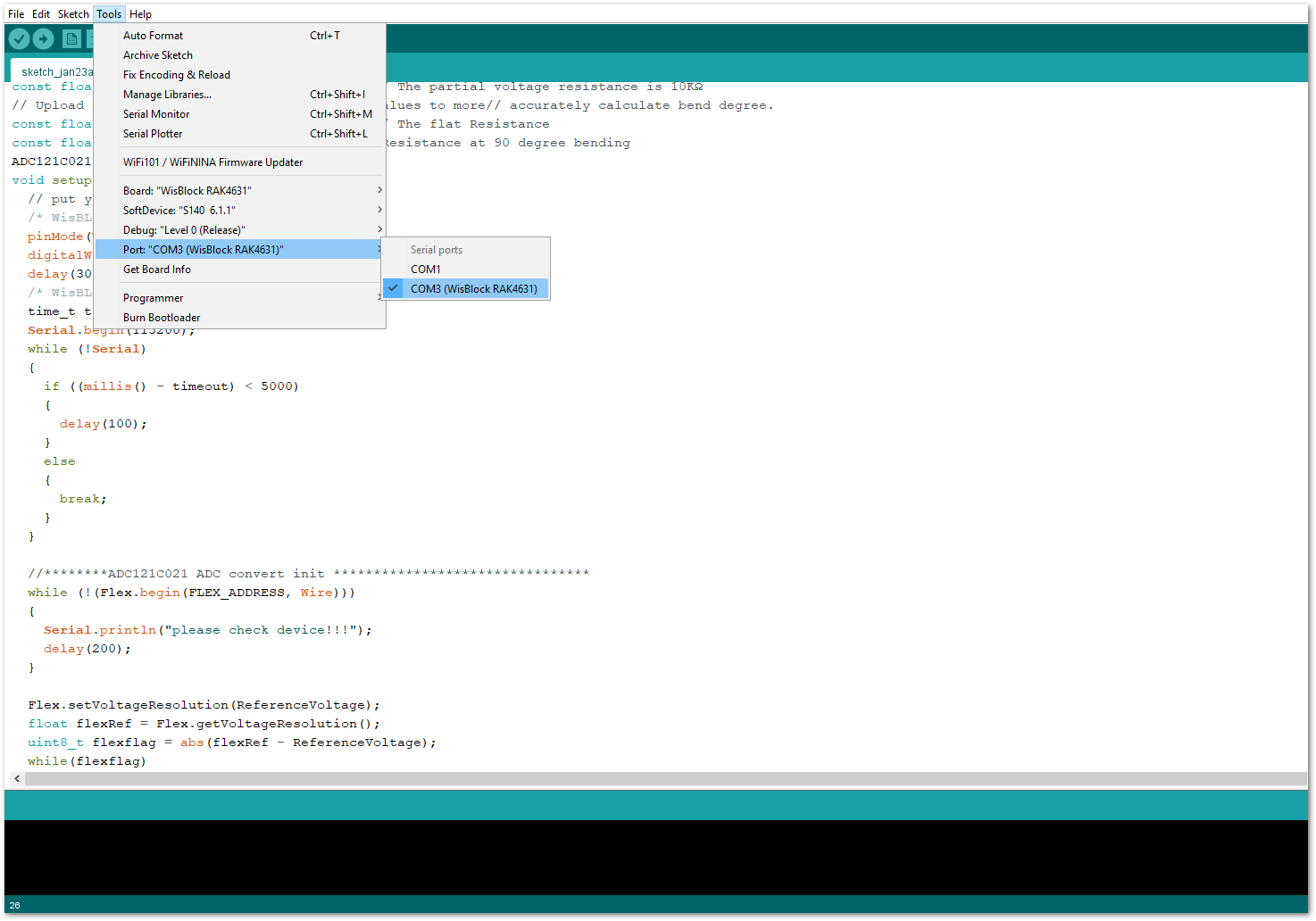 Figure 1: Selecting the correct Serial Port
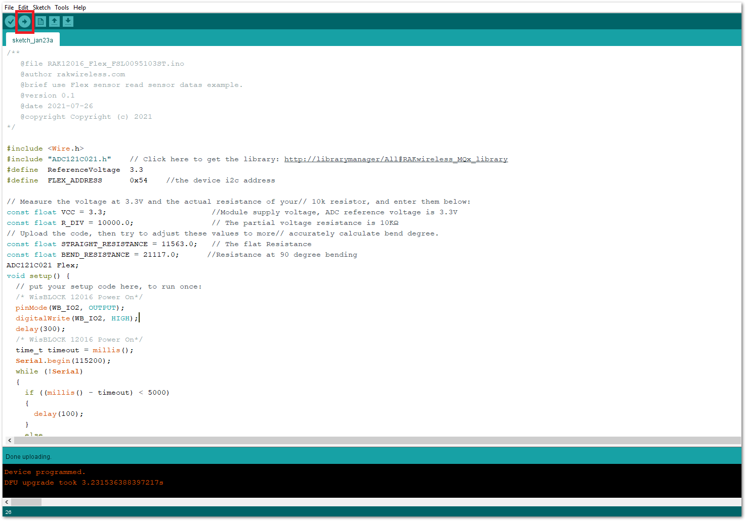 Figure 1: Uploading the RAK12016 example code
- When you successfully uploaded the example sketch, open the Serial Monitor of the Arduino IDE to see the sensor's reading logs, as shown in Figure 14. Try to bend the flex sensor, and you will see that the resistance readings increase, as well as the bent degrees. Therefore, your RAK12016 is properly communicating to the WisBlock core.
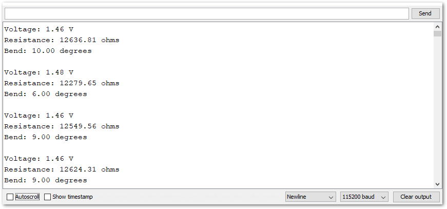 Figure 1: RAK12016 Flex Sensor readings