RAK13004 With RAK11200 WisBlock Core Guide
- First, you need to select the RAK11200 WisBlock Core.
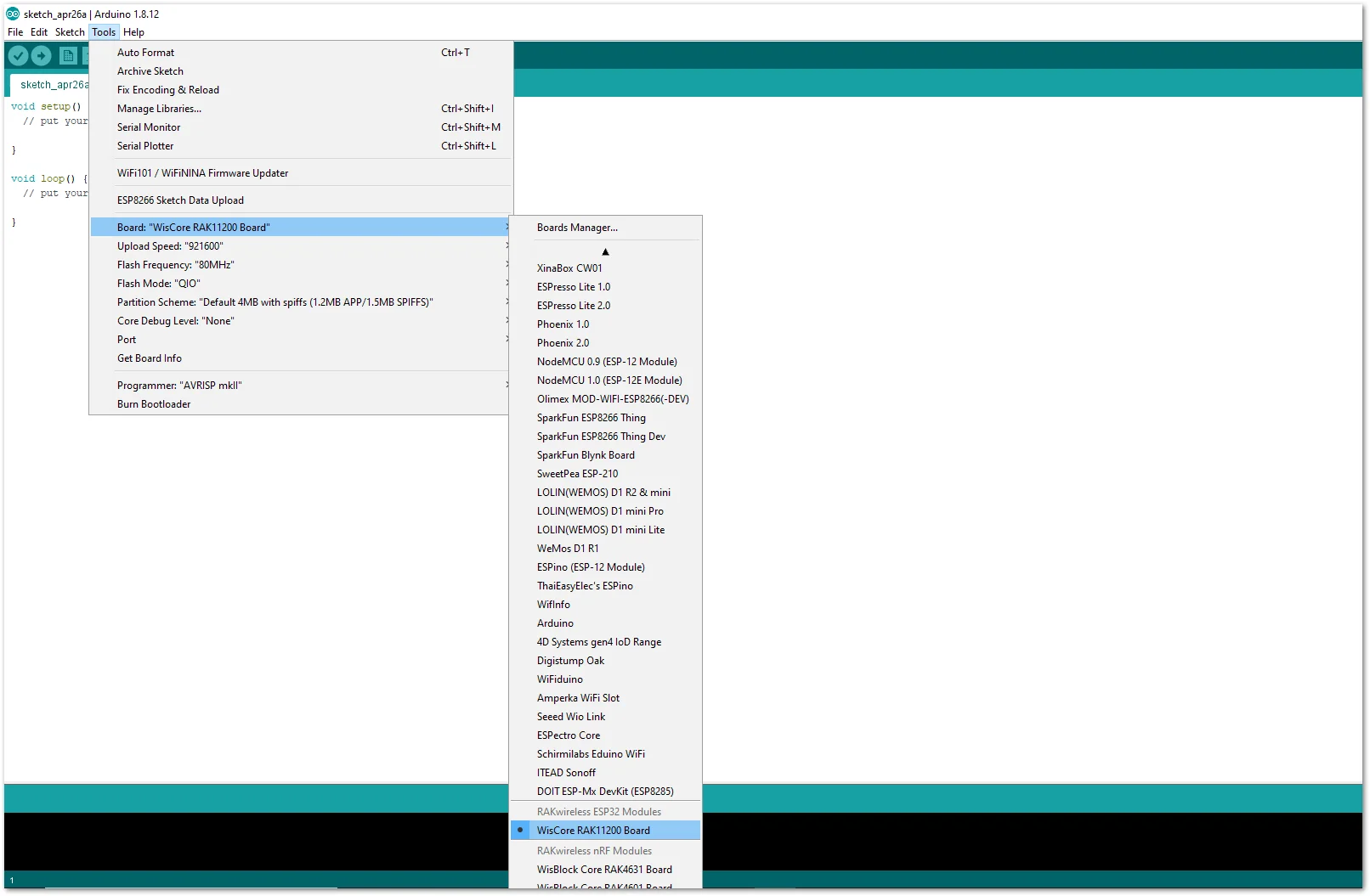 Figure 1: Selecting RAK11200 as WisBlock Core
- Next, copy the following sample code into your Arduino IDE.
Click to view the code
/**
   @file RAK13004_PWM_Expander_PCA9685.ino
   @author rakwireless.com
   @brief Use IIC to expand 16 PWM.
          Control PCA9685 channels 0~15 to output PWM with different duty cycles and time delays.
          The frequency can be adjusted supports 24HZ to 1526HZ.
   @version 0.1
   @date 2021-3-2
   @copyright Copyright (c) 2021
**/

#include <Arduino.h>
#include <PCA9685.h>  //Click the link to get the library: http://librarymanager/All#PCA9685

PCA9685 PCA9685;

void setup()
{
  pinMode(WB_IO2, OUTPUT);
  digitalWrite(WB_IO2, 1);

  PCA9685.setupSingleDevice(Wire,0x40);// Library using 0x40(0100 0000) i2c address, and default Wire @400kHz.

  PCA9685.setupOutputEnablePin(WB_IO6);// WB_IO6 active LOW output enable.
  PCA9685.enableOutputs(WB_IO6);

  PCA9685.setOutputsNotInverted();

  PCA9685.setToFrequency(500); // Set PWM freq to 500Hz (supports 24Hz to 1526Hz)

  // Set the PWM output of channel 0 .
  // PWM duty cycle = 50 % (LED on time = 50 %; LED off time = 50 %).
  // Delay time = 0 % .
  PCA9685.setChannelDutyCycle(0,  50, 0);
  PCA9685.setChannelDutyCycle(1,  50, 25);
  PCA9685.setChannelDutyCycle(2,  50, 50);
  PCA9685.setChannelDutyCycle(3,  10, 10);
  PCA9685.setChannelDutyCycle(4,  20, 20);
  PCA9685.setChannelDutyCycle(5,  30, 30);
  PCA9685.setChannelDutyCycle(6,  40, 40);
  PCA9685.setChannelDutyCycle(7,  50, 50);
  PCA9685.setChannelDutyCycle(8,  60, 60);
  PCA9685.setChannelDutyCycle(9,  70, 70);
  PCA9685.setChannelDutyCycle(10, 80, 80);
  PCA9685.setChannelDutyCycle(11, 90, 90);
  PCA9685.setChannelDutyCycle(12, 100, 0);
}

void loop()
{
  // Use channels 13, 14, 15 to make a simple breathing light example.
  for(uint8_t i=0 ;i < 100; i+=1)
  {
    PCA9685.setChannelDutyCycle(13, i,0);
    PCA9685.setChannelDutyCycle(14, 100-i,0);
    PCA9685.setChannelDutyCycle(15, i,0);
    delay(20);
  }
  for(uint8_t i=100 ;i >0; i-=1)
  {
    PCA9685.setChannelDutyCycle(13, i,0);
    PCA9685.setChannelDutyCycle(14, 100-i,0);
    PCA9685.setChannelDutyCycle(15, i,0);
    delay(20);
  }
}
NOTE
If you experience any error in compiling the example sketch, check the updated code for the RAK11200 WisBlock Core Module that can be found on the RAK13004 WisBlock Example Code Repository.
- Install the required library.
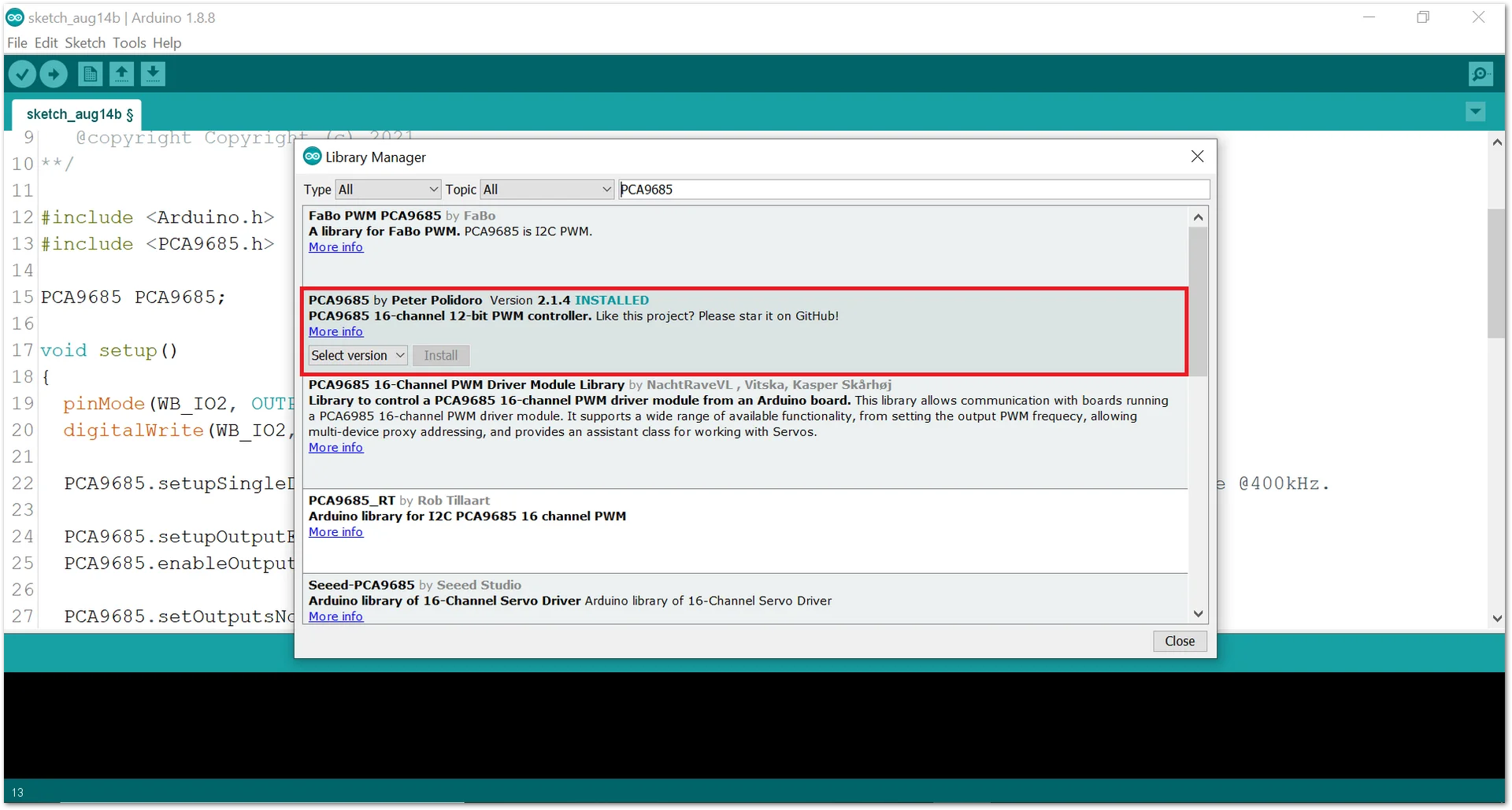 Figure 1: Installing the Library
- Select the correct port and upload your code.
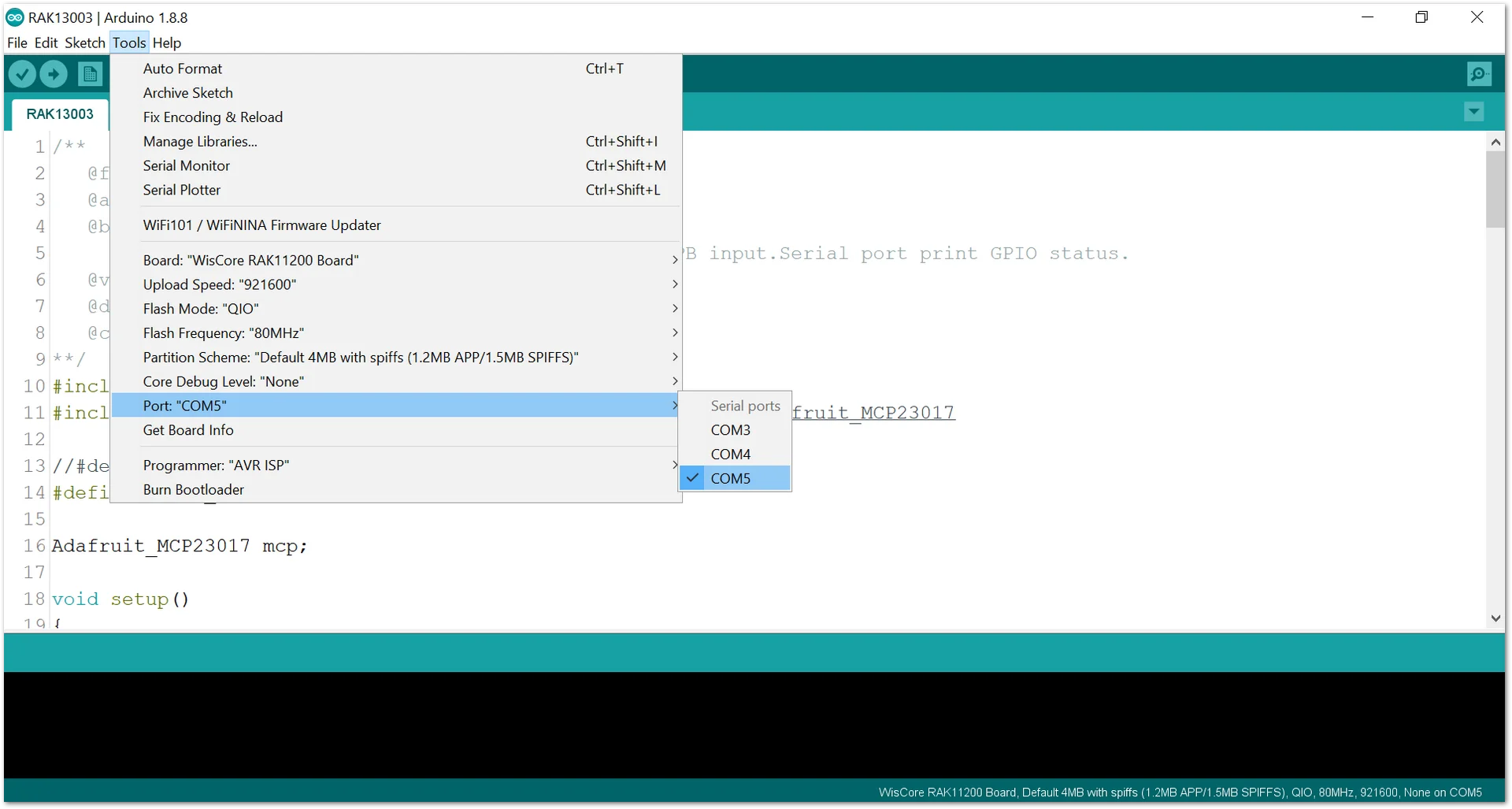 Figure 1: Selecting the correct Serial Port
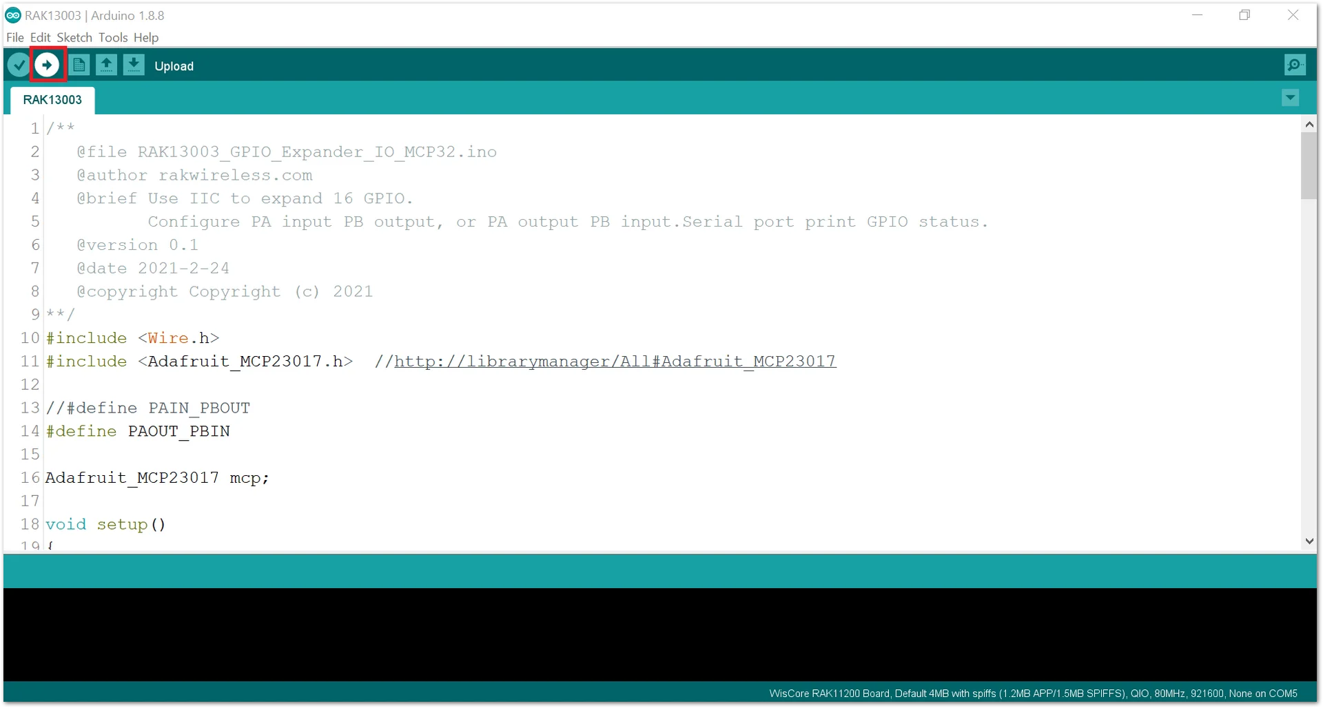 Figure 1: Uploading code
NOTE
RAK11200 requires the BOOT0 pin to be configured properly before uploading. If not done properly, uploading the source code to RAK11200 will fail. Check the full details on the RAK11200 Quick Start Guide.
- When you successfully uploaded the example sketch, you can see that the LEDs are fading in and out.


