RAK16000 WisBlock DC Current Module Quick Start Guide
Prerequisite
What Do You Need?
Before going through each and every step on using the RAK16000 WisBlock module, make sure to prepare the necessary items listed below:
Hardware
- RAK16000 WisBlock DC Current Sensor
- WisBlock Base with IO slot
- Your choice of WisBlock Core
- USB Cable
- Li-Ion/LiPo battery (optional)
- Solar charger (optional)
Software
Arduino
- Download and install Arduino IDE.
- To add the RAKwireless Core boards on your Arduino Boards Manager, install the RAKwireless Arduino BSP.
Product Configuration
Hardware Setup
RAK16000 is a part of the WisBlock Sensor Series that is capable of measuring DC current in the range of 0 to 3 A in a voltage range of 0 to 26 V. With the two measured DC values, you get the power consumption by multiplying the current and voltage. Additionally, this module uses the INA219BID from Texas Instruments that offers high accuracy maximum rate of 0.5% over temperature.
The current measurement method used is the high-side, where the shunt resistor is placed between the power supply and the load. This method allows the RAK16000 to measure both the circulating current and the voltage across the load.
For more information about the RAK16000, refer to the Datasheet.
Pin Definition
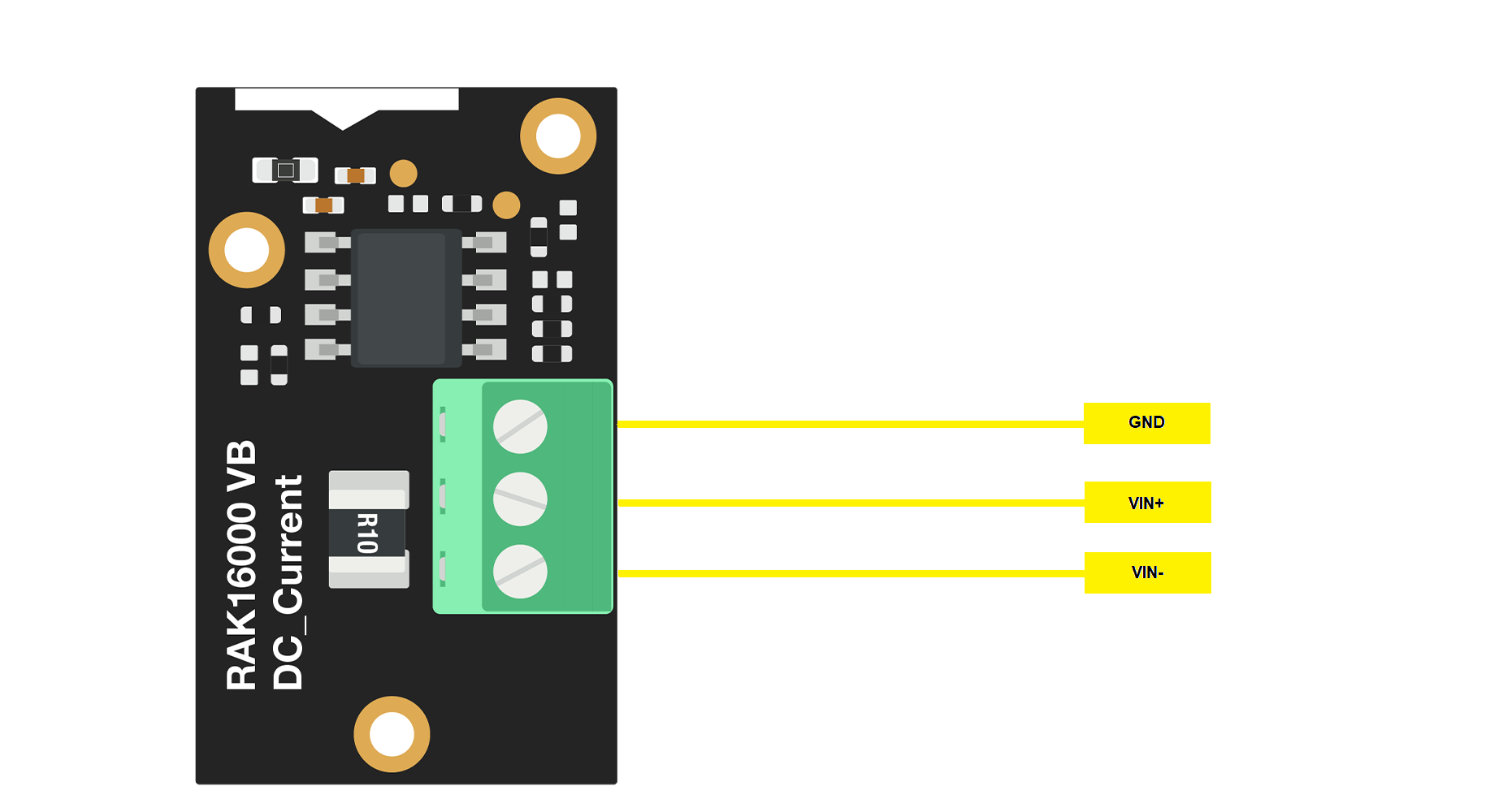 Figure 1: RAK16000 Pin Definition
- GND Connect to ground pin.
- VIN+ Connect to power supply pin
- VIN- Connect to load pin.
Assembling and Disassembling of WisBlock Modules
Assembling Procedure
As shown in Figure 2, the location for the IO slot is properly marked by silkscreen. Follow carefully the procedure defined in WisBlock Base board assembly/disassembly instructions to attach a WisBlock module. Once attached, carefully fix the module with one or more pieces of M1.2 x 3 mm screws depending on the module.
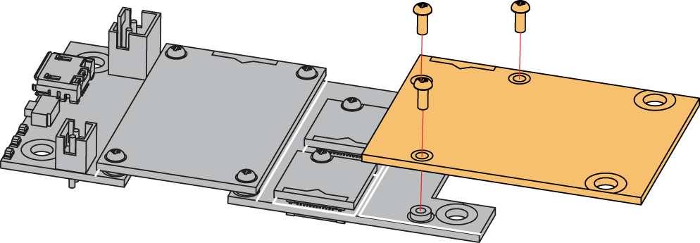 Figure 1: RAK16000 mounting connection to WisBlock Base module
Disassembling Procedure
The procedure in disassembling any type of WisBlock modules is the same.
- Remove the screws.
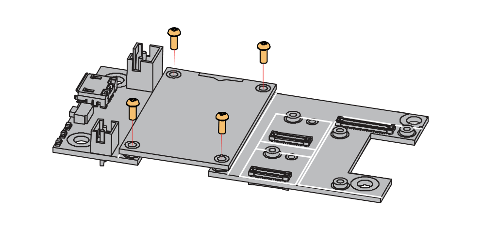 Figure 1: Removing screws from the WisBlock module
- Once the screws are removed, check the silkscreen of the module to find the correct location where force can be applied.
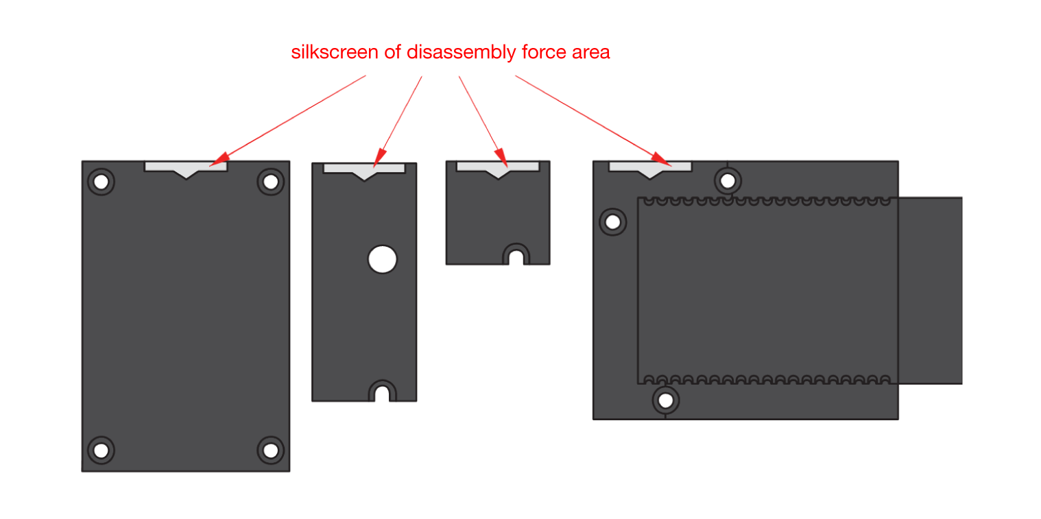 Figure 1: Detaching silkscreen on the WisBlock module
- Apply force to the module at the position of the connector, as shown in Figure 5, to detach the module from the baseboard.
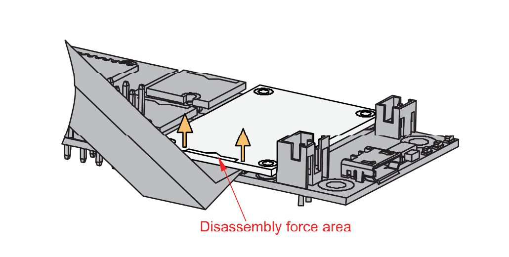 Figure 1: Applying even forces on the proper location of a WisBlock module
If you will connect other modules to the remaining WisBlock Base slots, check on the WisBlock Pin Mapper tool for possible conflicts.
Now, you can connect the battery (optional) and USB cable to start programming your WisBlock Core.
- Batteries can cause harm if not handled properly.
- Only 3.7-4.2 V Rechargeable LiPo batteries are supported. It is highly recommended not to use other types of batteries with the system unless you know what you are doing.
- If a non-rechargeable battery is used, it has to be unplugged first before connecting the USB cable to the USB port of the board to configure the device. Not doing so might damage the battery or cause a fire.
- Only 5 V solar panels are supported. Do not use 12 V solar panels. It will destroy the charging unit and eventually other electronic parts.
- Make sure the battery wires match the polarity on the WisBlock Base board. Not all batteries have the same wiring.
Software Configuration and Example
Initial Test of the RAK16000 WisBlock Module
-
Install the RAKwireless Arduino BSP's for WisBlock by using the
package_rakwireless_index.jsonboard installation package, the WisBlock Core should now be available on the Arduino IDE. -
You need to select first the WisBlock Core you have.
RAK4631 Board
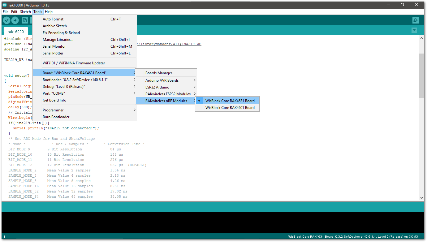 Figure 1: Selecting RAK4631 as WisBlock Core
RAK11200 Board
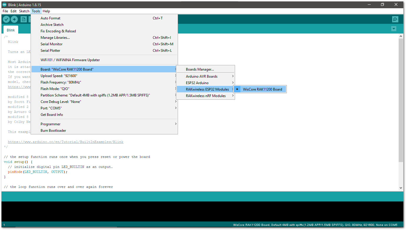 Figure 1: Selecting RAK11200 as WisBlock Core
RAK11310
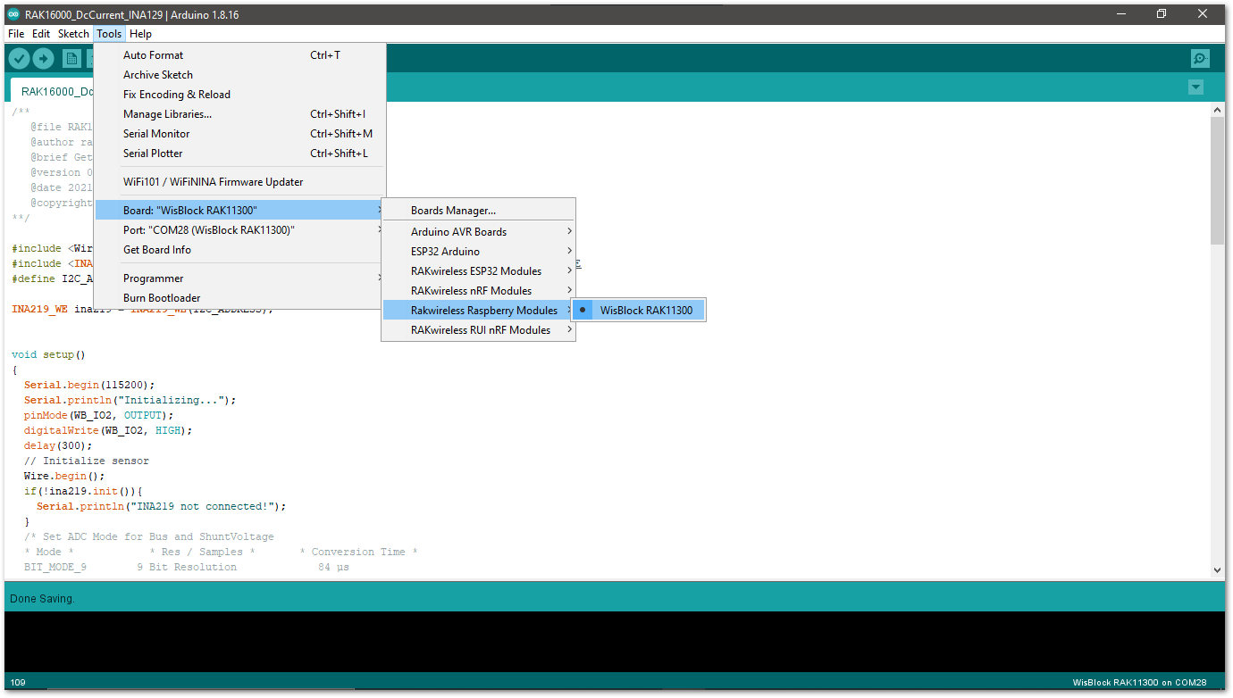 Figure 1: Selecting RAK11310 as WisBlock Core
- Copy the following sample code into your Arduino IDE:
Click to view the example
/**
   @file RAK16000_DcCurrent_INA219.ino
   @author rakwireless.com
   @brief Get DC current from sensor
   @version 0.1
   @date 2021-7-28
   @copyright Copyright (c) 2020
**/

#include <Wire.h>
#include <INA219_WE.h>// Click here to get the library: http://librarymanager/All#INA219_WE
#define I2C_ADDRESS 0x41

INA219_WE ina219 = INA219_WE(I2C_ADDRESS);

void setup()
{
  Serial.begin(115200);
  Serial.println("Initializing...");
  pinMode(WB_IO2, OUTPUT);
  digitalWrite(WB_IO2, HIGH);
  delay(300);
  // Initialize sensor
  Wire.begin();
  if(!ina219.init()){
    Serial.println("INA219 not connected!");
  }
  /* Set ADC Mode for Bus and ShuntVoltage
  * Mode *            * Res / Samples *       * Conversion Time *
  BIT_MODE_9        9 Bit Resolution             84 µs
  BIT_MODE_10       10 Bit Resolution            148 µs
  BIT_MODE_11       11 Bit Resolution            276 µs
  BIT_MODE_12       12 Bit Resolution            532 µs  (DEFAULT)
  SAMPLE_MODE_2     Mean Value 2 samples         1.06 ms
  SAMPLE_MODE_4     Mean Value 4 samples         2.13 ms
  SAMPLE_MODE_8     Mean Value 8 samples         4.26 ms
  SAMPLE_MODE_16    Mean Value 16 samples        8.51 ms
  SAMPLE_MODE_32    Mean Value 32 samples        17.02 ms
  SAMPLE_MODE_64    Mean Value 64 samples        34.05 ms
  SAMPLE_MODE_128   Mean Value 128 samples       68.10 ms
  */
  ina219.setADCMode(SAMPLE_MODE_128); // choose mode and uncomment for change of default

  /* Set measure mode
  POWER_DOWN - INA219 switched off
  TRIGGERED  - measurement on demand
  ADC_OFF    - Analog/Digital Converter switched off
  CONTINUOUS  - Continuous measurements (DEFAULT)
  */
  ina219.setMeasureMode(CONTINUOUS); // choose mode and uncomment for change of default

  /* Set PGain
  * Gain *  * Shunt Voltage Range *   * Max Current (if shunt is 0.1 ohms) *
   PG_40       40 mV                    0.4 A
   PG_80       80 mV                    0.8 A
   PG_160      160 mV                   1.6 A
   PG_320      320 mV                   3.2 A (DEFAULT)
  */
  ina219.setPGain(PG_320); // choose gain and uncomment for change of default

  /* Set Bus Voltage Range
   BRNG_16   -> 16 V
   BRNG_32   -> 32 V (DEFAULT)
  */
  ina219.setBusRange(BRNG_32); // choose range and uncomment for change of default
  ina219.setShuntSizeInOhms(0.1); // we use 100ohm
  Serial.println("INA219 Current Sensor Example Sketch - Continuous");

  /* If the current values delivered by the INA219 differ by a constant factor
     from values obtained with calibrated equipment you can define a correction factor.
     Correction factor = current delivered from calibrated equipment / current delivered by INA219
  */
  ina219.setCorrectionFactor(0.99); // insert your correction factor if necessary
}

void loop()
{
  float shuntVoltage_mV = 0.0;
  float loadVoltage_V = 0.0;
  float busVoltage_V = 0.0;
  float current_mA = 0.0;
  float power_mW = 0.0;
  bool ina219_overflow = false;

  shuntVoltage_mV = ina219.getShuntVoltage_mV();
  busVoltage_V = ina219.getBusVoltage_V();
  //here we use the I=U/R to calculate, here the Resistor is 100mΩ, accuracy can reach to 0.5%.
  current_mA = shuntVoltage_mV/0.1;
  power_mW = ina219.getBusPower();
  loadVoltage_V  = busVoltage_V + (shuntVoltage_mV/1000);
  ina219_overflow = ina219.getOverflow();

  Serial.print("Shunt Voltage [mV]: "); Serial.println(shuntVoltage_mV);
  Serial.print("Bus Voltage [V]: "); Serial.println(busVoltage_V);
  Serial.print("Load Voltage [V]: "); Serial.println(loadVoltage_V);
  Serial.print("Current[mA]: "); Serial.println(current_mA);
  Serial.print("Bus Power [mW]: "); Serial.println(power_mW);
  if(!ina219_overflow){
    Serial.println("Values OK - no overflow");
  }
  else{
    Serial.println("Overflow! Choose higher PGAIN");
  }
  Serial.println();

  delay(1000);
}
If you experience any error in compiling the example sketch, check the updated code for your WisBlock Core Module that can be found on the RAK16000 WisBlock Example Code Repository and this sample code in Github will work on all WisBlock Core.
- Once the example sketch is open, install the INA219_WE library by clicking the yellow-highlighted link, as shown in Figure 9 and Figure 10.
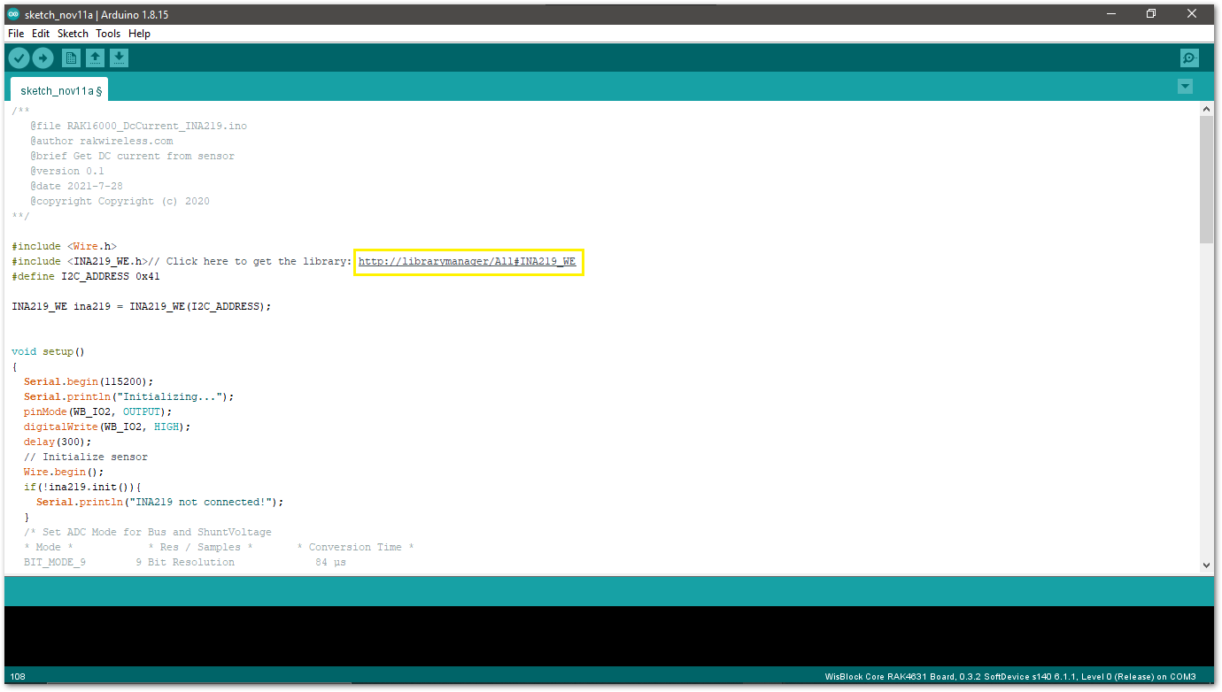 Figure 1: Install INA219_WE Library
Click on the Install button to finish library installation.
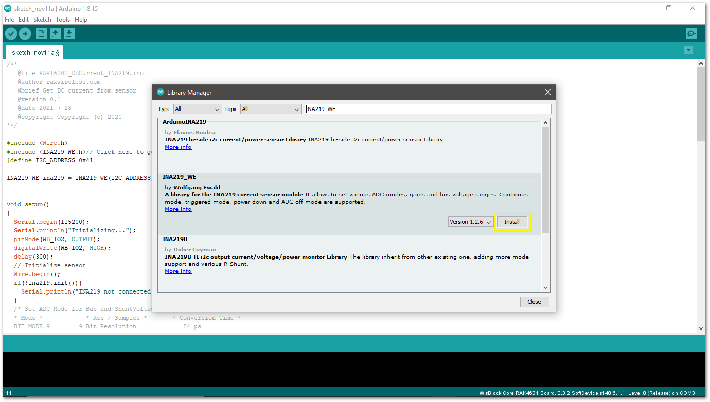 Figure 1: Arduino Library Manager INA219_WE
- Select the right port and upload the code, as shown in Figure 11 and Figure 12.
If you are using the RAK11200 as your WisBlock Core, the RAK11200 requires the Boot0 pin to be configured properly first before uploading. If not done properly, uploading the source code to RAK11200 will fail. Check the full details on the RAK11200 Quick Start Guide.
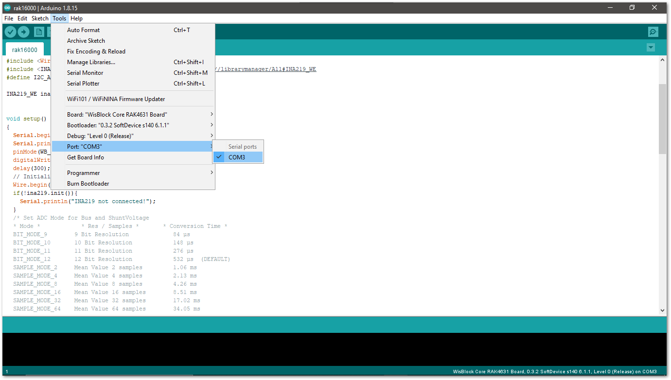 Figure 1: Selecting the correct Serial Port
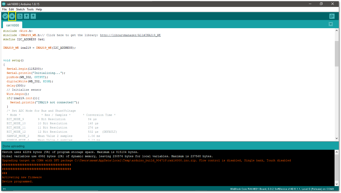 Figure 1: Uploading the RAK16000 Sample code
- After successful upload, open Arduino Serial Monitor and check the current current consumption and load voltage.
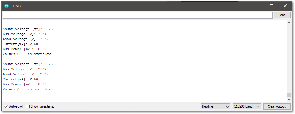 Figure 1: RAK16000 Serial Monitor