RAK18030 WisBlock Audio PDM Microphone Module Quick Start Guide
Prerequisite
What Do You Need?
Before going through each and every step on using the RAK18030 WisBlock module, make sure to prepare the necessary items listed below:
Hardware
- RAK18030 WisBlock PDM Mono Microphone Module
- Your choice of WisBlock Base with IO slot
- Your choice of WisBlock Core
- USB Cable
- Li-Ion/LiPo battery (optional)
- Solar charger (optional)
Software
- Download and install ArduinoIDE.
- To add the RAKwireless Core boards on your Arduino board, install the RAKwireless Arduino BSP. Follow the steps in the GitHub repo.
Product Configuration
Hardware Setup
RAK18030 is a WisBlock mono PDM microphone module that extends the WisBlock system with sound-sensing capability.
For more information about RAK18030, refer to the Datasheet.
RAK18030 module can be connected to the IO slot of the WisBlock Base to communicate with the WisBlock Core. Always secure the connection of the WisBlock module by using compatible screws.
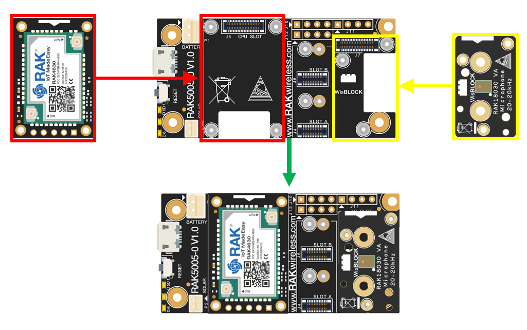 Figure 1: RAK18030 connection to WisBlock Base
Assembling and Disassembling of WisBlock Modules
Assembling
As shown in Figure 2, the location for the IO slot is properly marked by silkscreen. Follow carefully the procedure defined in WisBlock Base board assembly/disassembly instructions to attach a WisBlock module. Once attached, carefully fix the module with one or more pieces of M1.2 x 3 mm screws depending on the module.
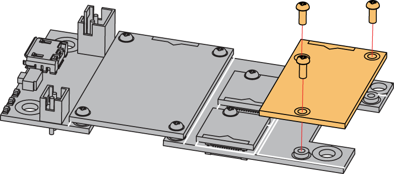 Figure 1: RAK18030 connection to WisBlock Base
When using the RAK4631 board, connect the LoRa and BLE antennas to avoid damage to the board.
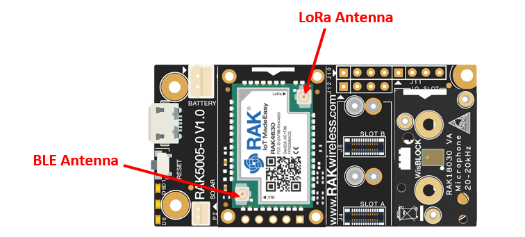 Figure 1: LoRa and BLE antennas of RAK4631
Disassembling
The procedure in disassembling any type of WisBlock module is the same.
- First, remove the screws.
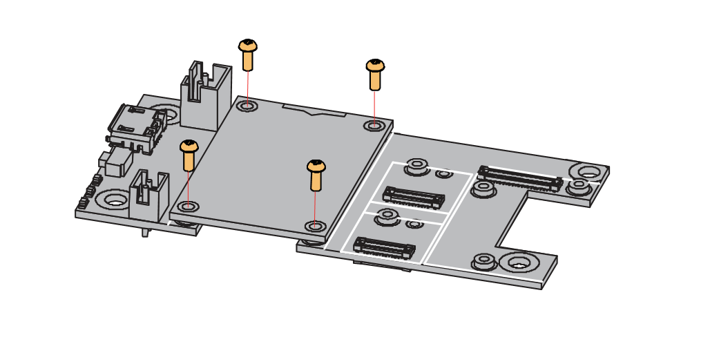 Figure 1: Removing screws from the WisBlock module
- Once the screws are removed, check the silkscreen of the module to find the correct location where force can be applied.
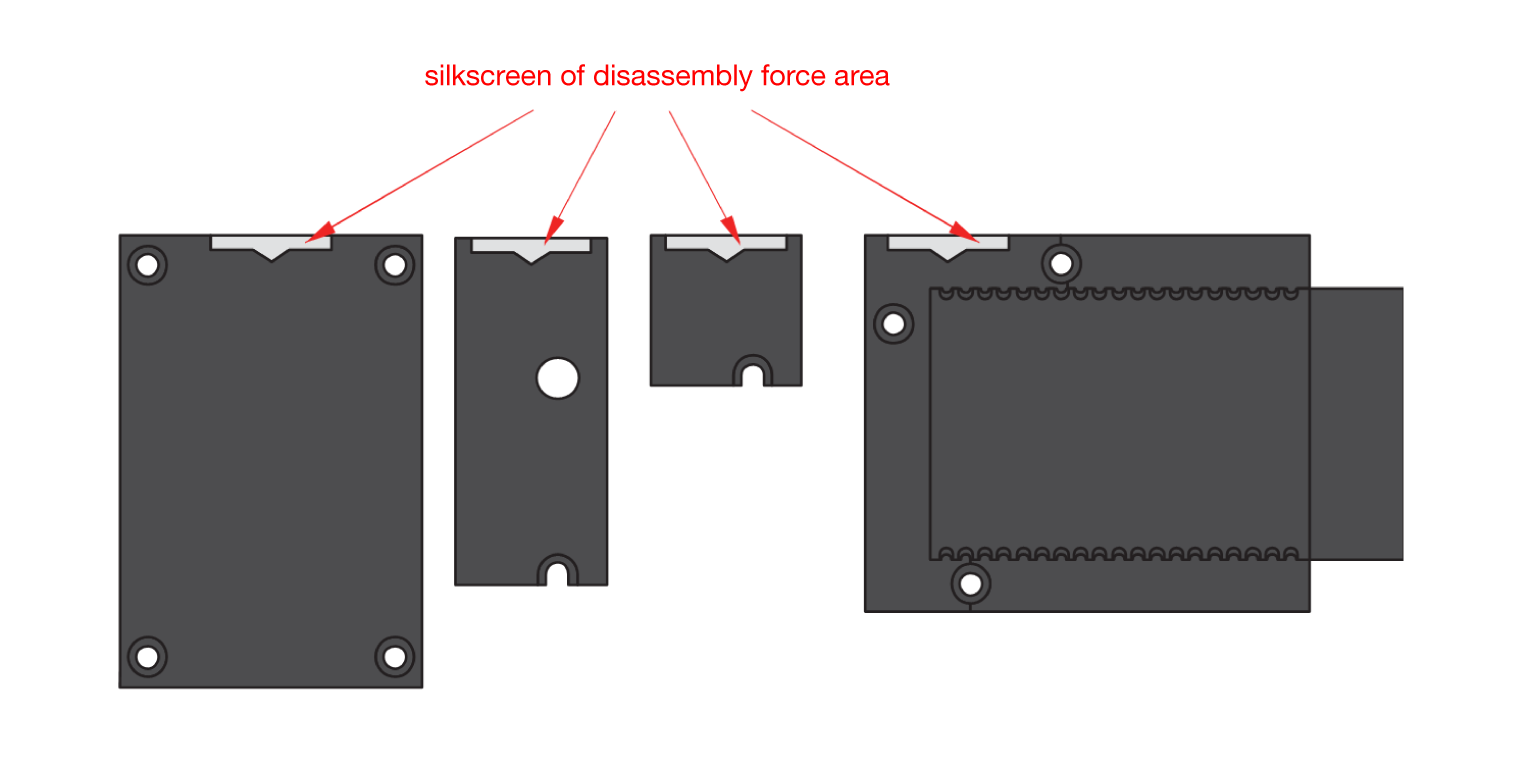 Figure 1: Detaching silkscreen on the WisBlock module
- Apply force to the module at the position of the connector, as shown in Figure 6, to detach the module from the baseboard.
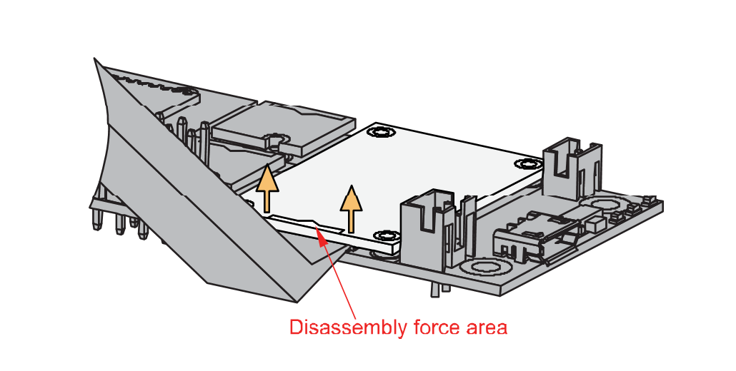 Figure 1: Applying even forces on the proper location of a WisBlock module
If you will connect other modules to the remaining WisBlock Base slots, check on the WisBlock Pin Mapper tool for possible conflicts. RAK18030 uses I2C communication lines, and it can cause possible conflict, especially on other WisBlock Modules connected to Slot A to F of the WisBlock Base.
After all this setup, you can now connect the battery (optional) and USB cable to start programming your WisBlock Core.
- Batteries can cause harm if not handled properly.
- Only 3.7-4.2 V Rechargeable LiPo batteries are supported. It is highly recommended not to use other types of batteries with the system unless you know what you are doing.
- If a non-rechargeable battery is used, it has to be unplugged first before connecting the USB cable to the USB port of the board to configure the device. Not doing so might damage the battery or cause a fire.
- Only 5 V solar panels are supported. Do not use 12 V solar panels. It will destroy the charging unit and eventually other electronic parts.
- Make sure the battery wires match the polarity on the WisBlock Base board. Not all batteries have the same wiring.
Software Configuration and Example
The RAK18030 design is based on the SPK0641HT4H-1 microphone module from Knowles. The RAK18030 is a mono PDM microphone module that is used to convert analog audio into a Pulse Density Modulation (PDM) output. It can be used for audio monitoring, recording, and even voice control functions. For this example, you will be using the RAK4631 as your WisBlock Core.
Initial Test of the RAK18030 WisBlock Module
- Install the RAKwireless Arduino BSP for WisBlock by using the
package_rakwireless_index.jsonboard installation package. The WisBlock Core should now be available on the Arduino IDE.
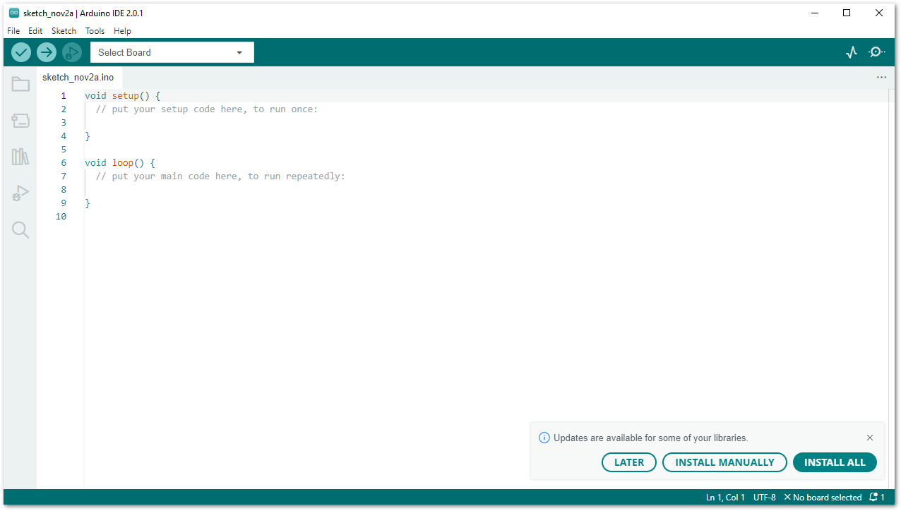 Figure 1: Arduino IDE
- Then you also need to install the latest RAKwireless Audio Library using the Library Manager of Arduino IDE.
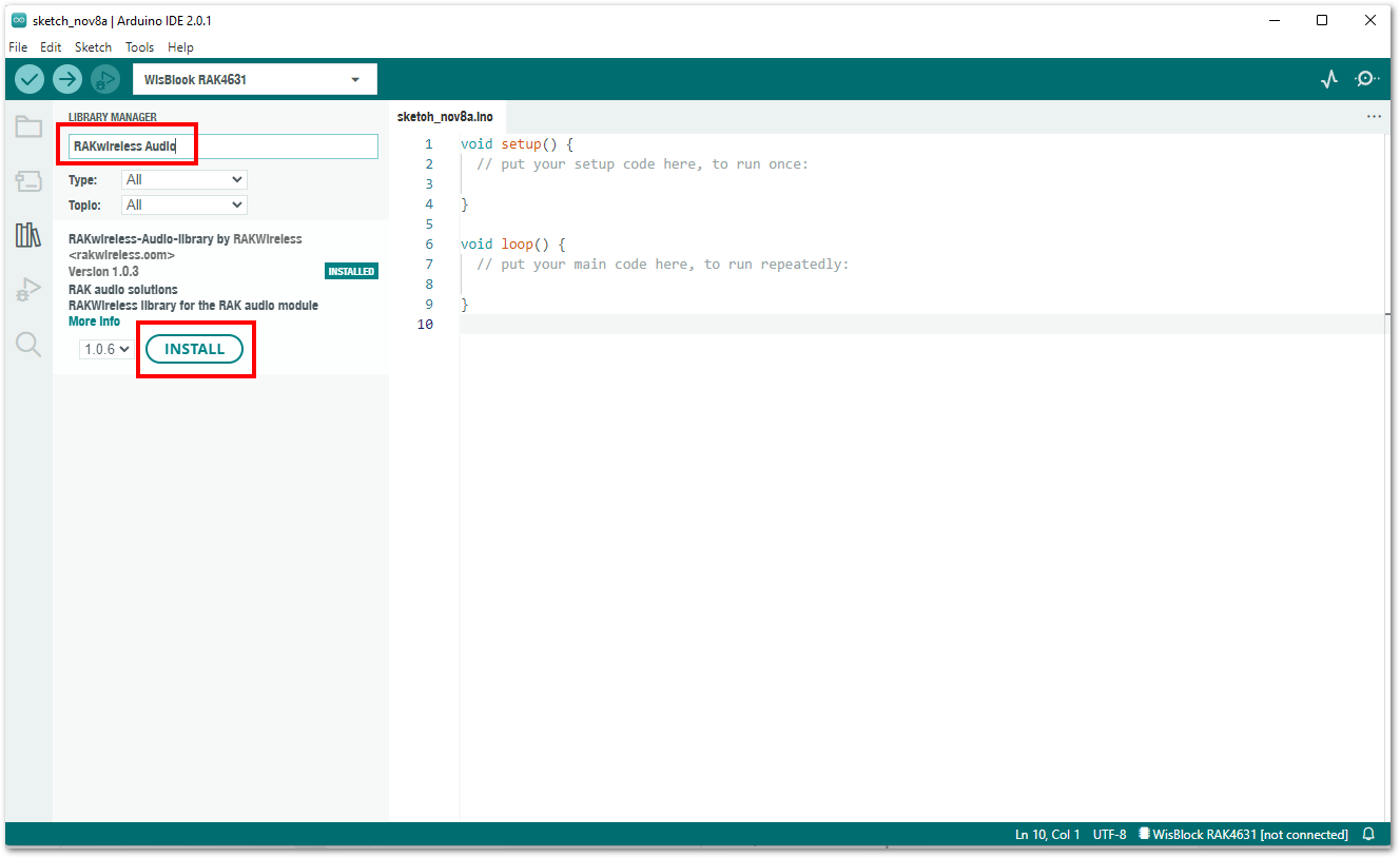 Figure 1: RAKwireless Audio Library
- Open the sample code for RAK18030 from RAK4631 examples.
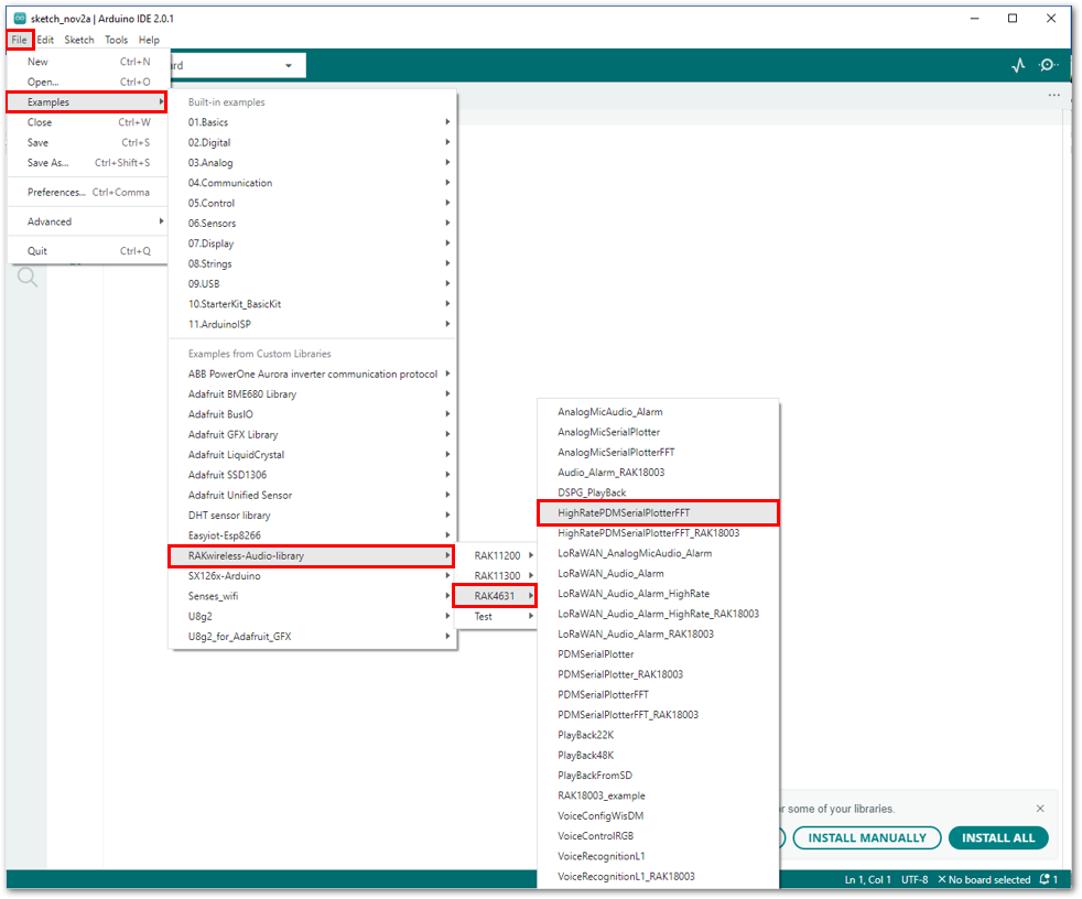 Figure 1: Selecting the sample code for RAK18030
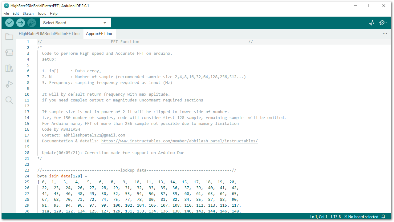 Figure 1: Sample code for RAK18030
- Then select the RAK4631 board and its serial port, as shown in Figure 11 and Figure 12.
The example codes of RAKwireless Audio Library are compatible with specific WisBlock Core. You have to select the correct WisBlock Core based on what core you used in your application.
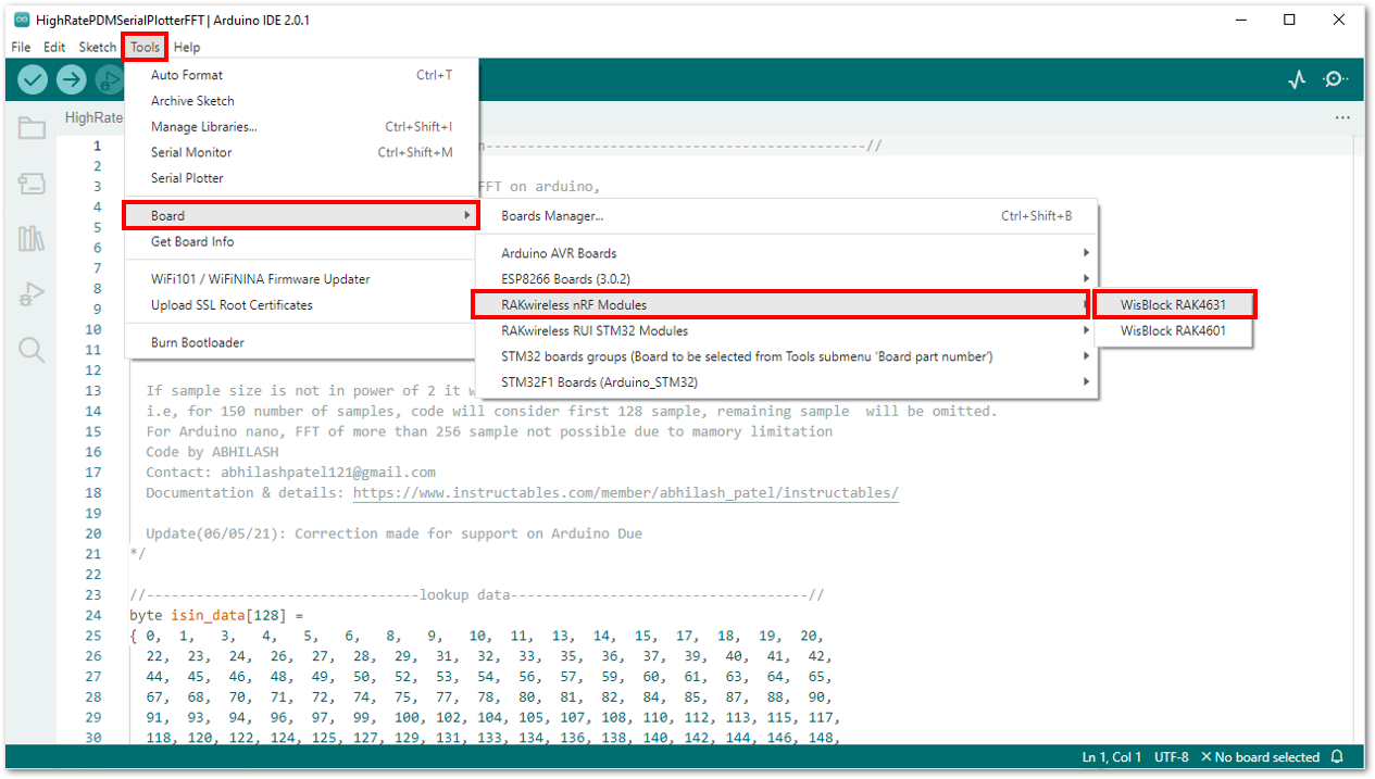 Figure 1: Selecting RAK4631 board as the WisBlock Core
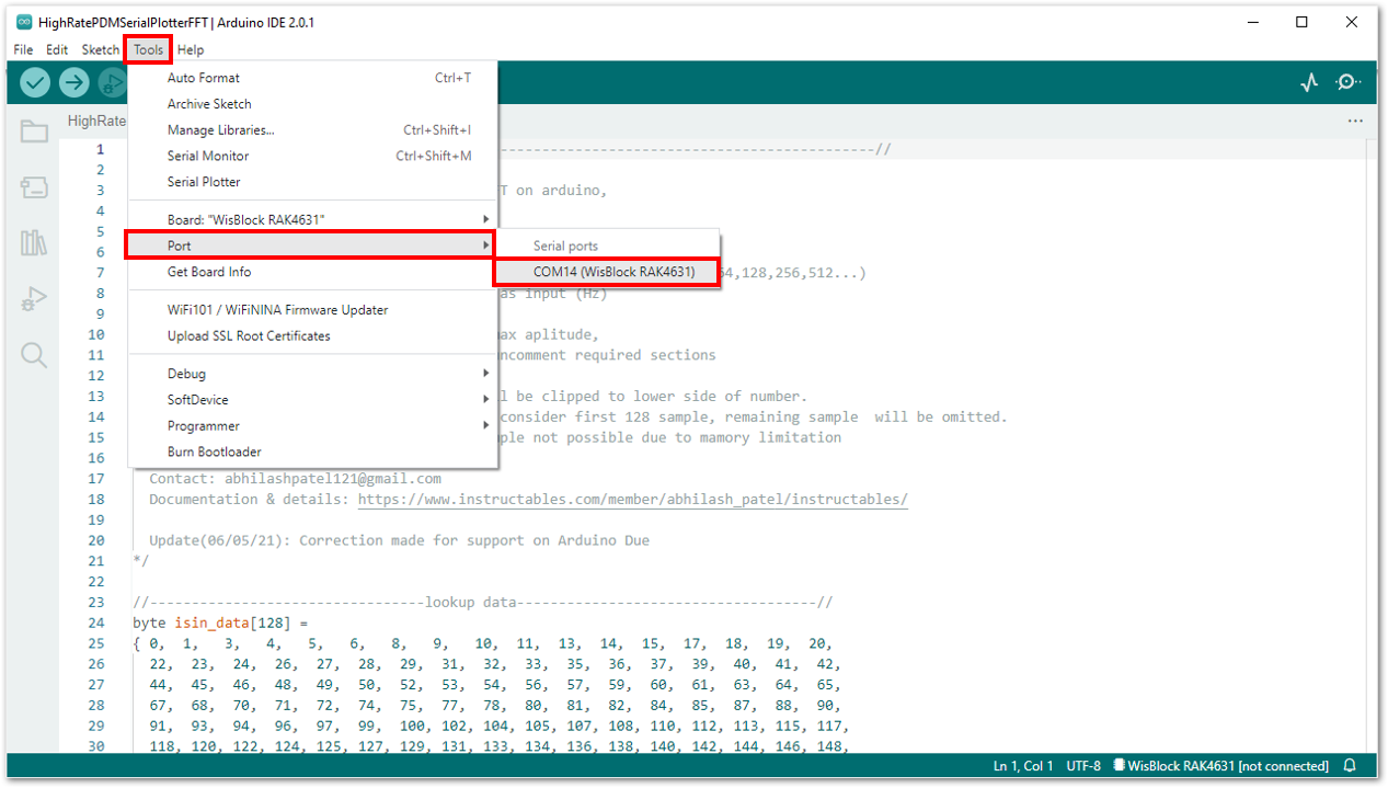 Figure 1: Selecting the serial port of RAK4631 WisBlock Core
- Then upload the code as shown in Figure 13 and Figure 14.
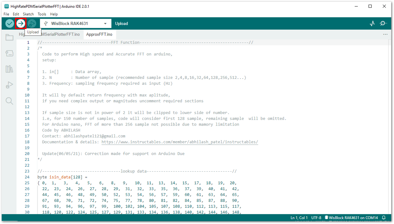 Figure 1: Uploading the RAK18030 code
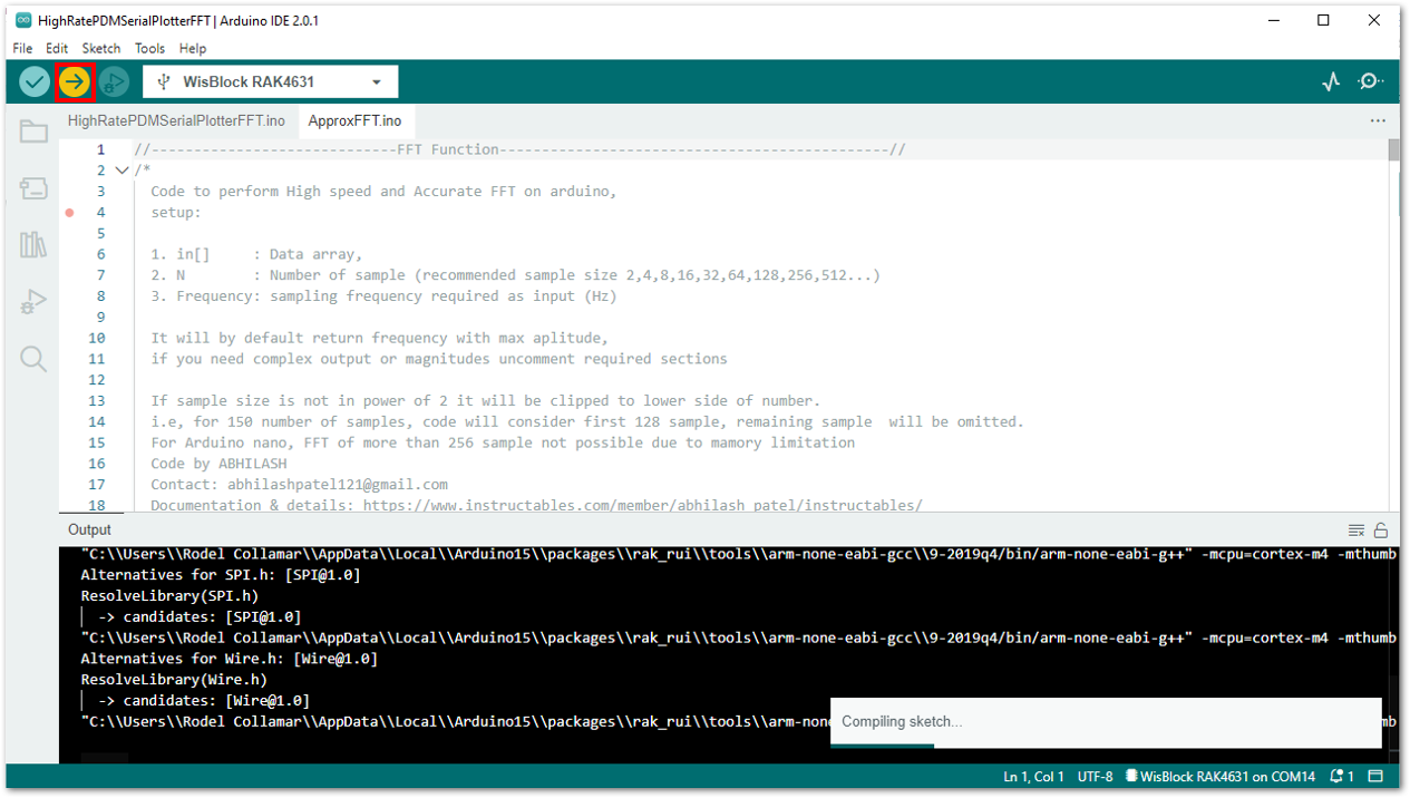 Figure 1: Uploading the RAK18030 code
If you experience any error in compiling the example sketch, check the updated example code for your WisBlock Core Module that can be found on the RAKwireless Audio Library.
- When you successfully uploaded the sample code, open the Serial Plotter of the Arduino IDE to see the sensor's reading logs. To test the sound detection, you can download a sound-generating app on your smartphone and sweep frequencies starting from 1000 Hz to 10000 Hz. If you see the plot, then your RAK18030 is properly communicating to the WisBlock core.
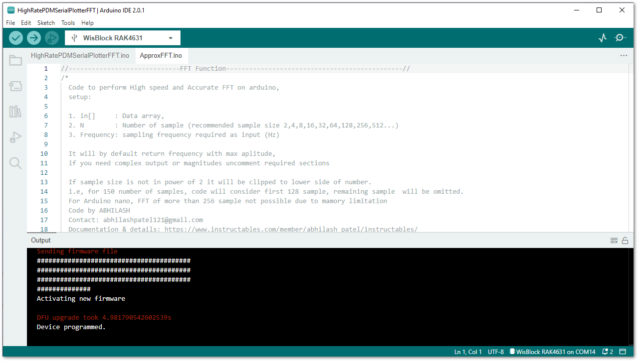 Figure 1: Sample code successfully uploaded to RAK4631
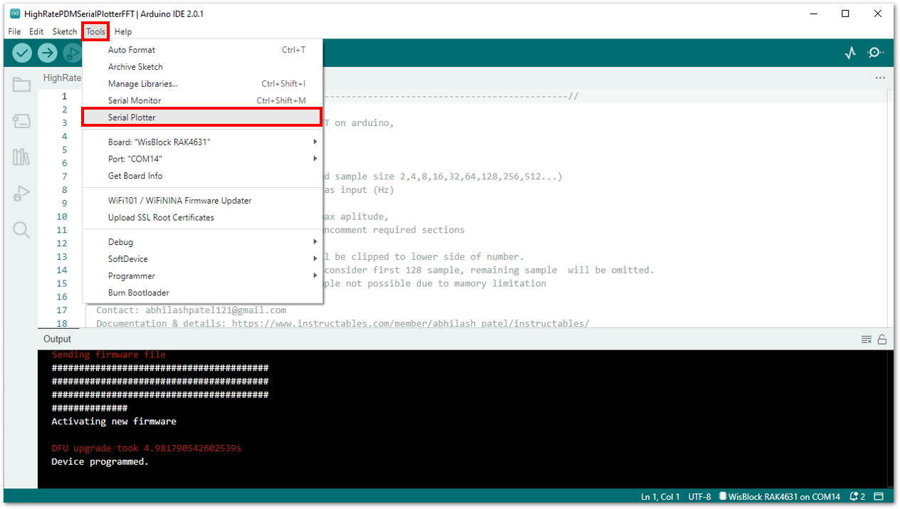 Figure 1: Opening the Serial Plotter
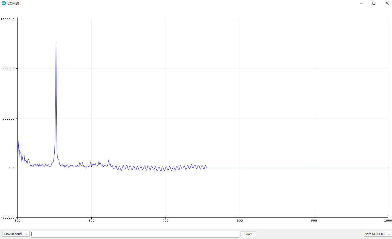 Figure 1: FTT Plot of 10kHz sample signal
If there is no serial plot graph shown in Arduino 2.0.x, you can try the serial plotter of the legacy Arduino 1.8.x IDE.
