RAK1920 WisBlock Sensor Adapter Module Datasheet
Overview
Description
The RAK1920 module, a part of the WisBlock Interface series, is a sensor extension module, which extends the WisBlock system with an adapter board to connect Click Boards (MikroElektronika), QWICC (Sparkfun) based and Grove (Seeed) based sensors to WisBlock. This module was designed to be part of a production-ready IoT solution in a modular way and must be combined with a WisBlock Core and a Base module.
It supports several defacto-standard interfaces in the IoT market and allows you to integrate sensors manufactured by Mikroe, SparkFun, SeeedStudio, and others. For example, the RAK1920 supports the Click Boards™ series of modules provided by Mikroe, Qwiic Connect™ sensor interface designed by SparkFun. Also, it supports all kinds of I2C module digital I/O, UART, and ADC sensors with a Grove™ interface.
Features
- Interface to all Click Boards of Mikroe
- Interface to all Qwiic sensors of SparkFun
- Interface to all I2C and Digital I/O sensors of Grove
- Interface to UART and ADC sensors options of Grove
- Reserved I2C interface
- 3.3 V and 5 V sensors options
Specifications
Overview
The RAK1920 module supports Mikroe’s Click Boards, Sparkfun’s Qwiic Connect, and Seeed’s Grove sensors. Figure 1 shows the sensors’ connector available in the RAK1920.
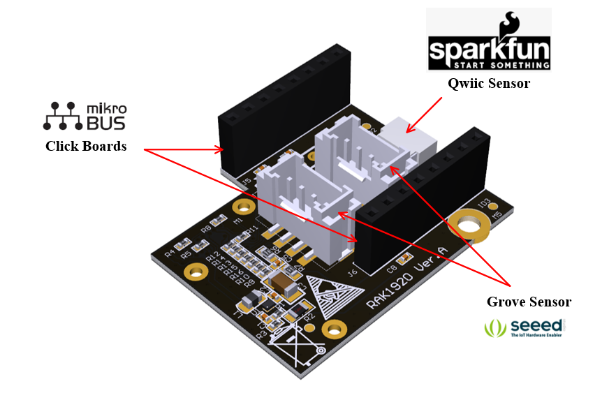 Figure 1: RAK1920 sensor extension interface
Mounting
Figure 2 shows how the RAK1920 module is integrated with the RAK5005-O baseboard, and the mounting sketch is also shown.
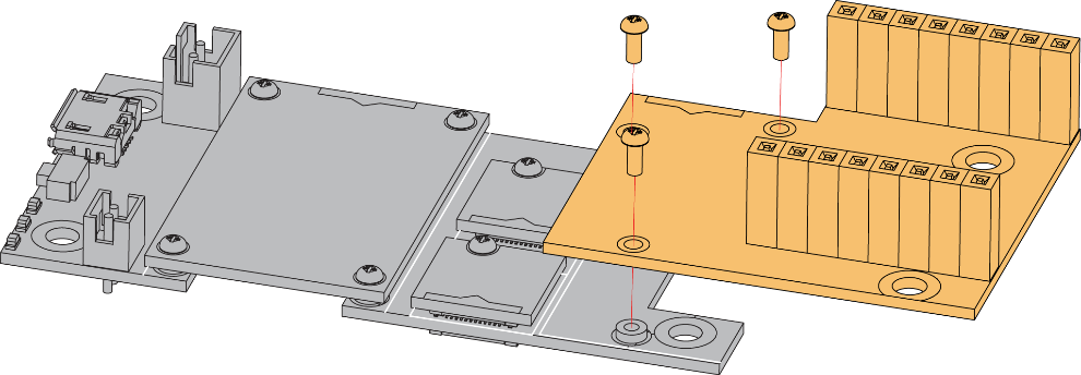 Figure 1: RAK1920 Mounting Sketch
Hardware
The hardware specification is categorized into four parts. It discusses the interfacing, its corresponding functions and the diagram of the module as well. It also covers the electrical and mechanical parameters that include the tabular data of the functionalities and standard values of the RAK1920 WisBlock Sensor Adapter Module.
Interfaces
Mikroe Click Boards Interfaces
The RAK1920 supports all the Click boards modules manufactured by Mikroe through the mikroBUS™ interface. Figure 3 shows the pin out diagram of the mikroBUS.
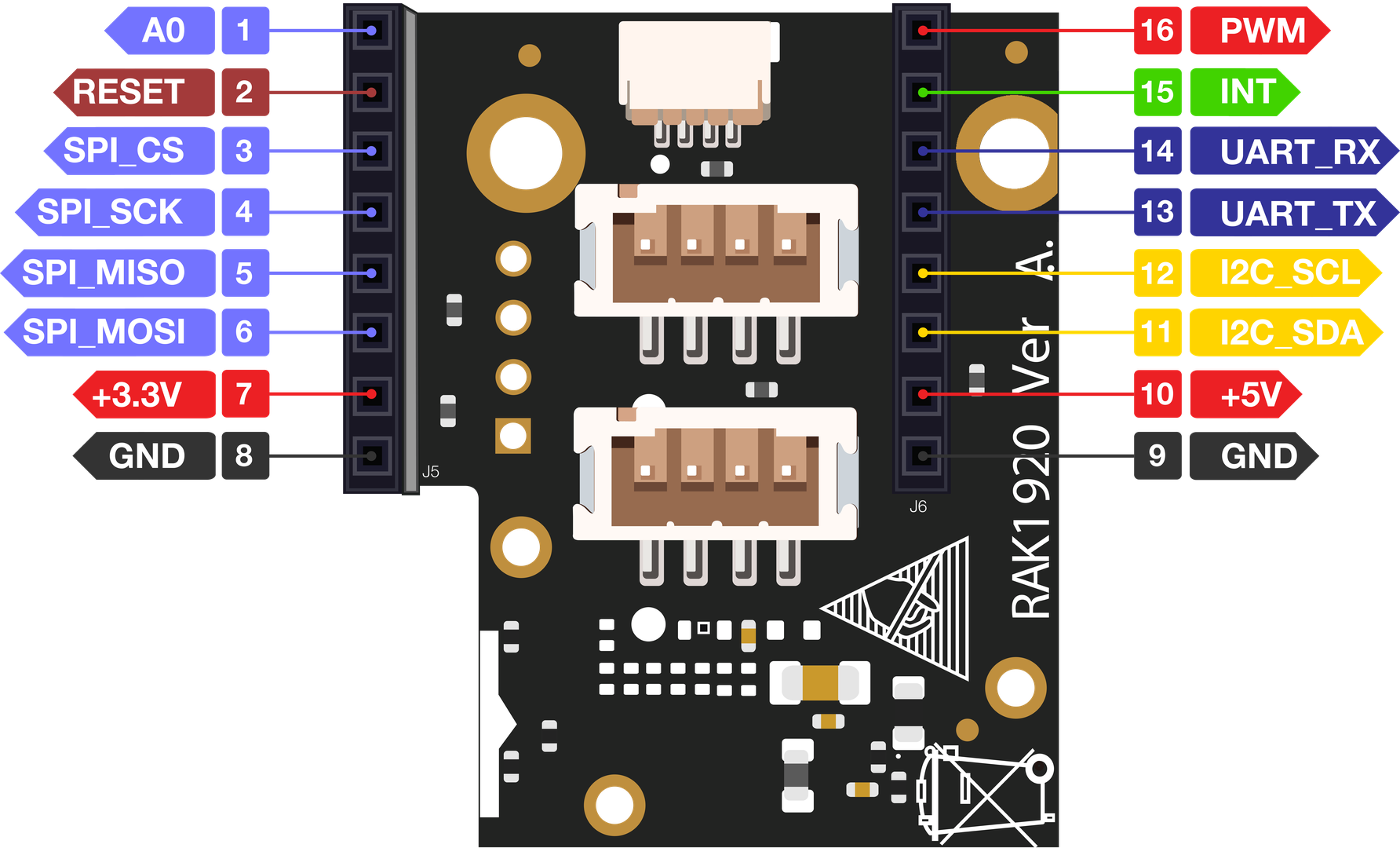 Figure 1: Mikroe’s mikroBUS® interface
| Pin No. | Label | Pin Definition |
|---|---|---|
| 1 | A0 | Analog |
| 2 | RESET | Reset |
| 3 | SPI_CS | SPI Chip Select |
| 4 | SPI_CK | SPI Clock |
| 5 | SPI_MISO | SPI Master Input Slave Output |
| 6 | SPI_MOSI | SPI Master Output Slave Input |
| 7 | +3.3 V | VCC 3.3 V Power |
| 8 | GND | Reference Ground |
| 9 | GND | Reference Ground |
| 10 | +5 V | VCC 5.5 V Power |
| 11 | I2C_SDA | I2C Data |
| 12 | I2C_SCL | I2C Clock |
| 13 | UART_TX | UART Transmit |
| 14 | UART_RX | UART Receive |
| 15 | INT | Hardware Interrupt |
| 16 | PWM | PWM Input |
Grove Sensor Interfaces
The RAK1920 module supports the Grove I2C and digital I/O sensors. Figure 4 shows the pin number and definition of the Grove sensor. By default, VCC is connected to the 3.3 V line of the IO connector.
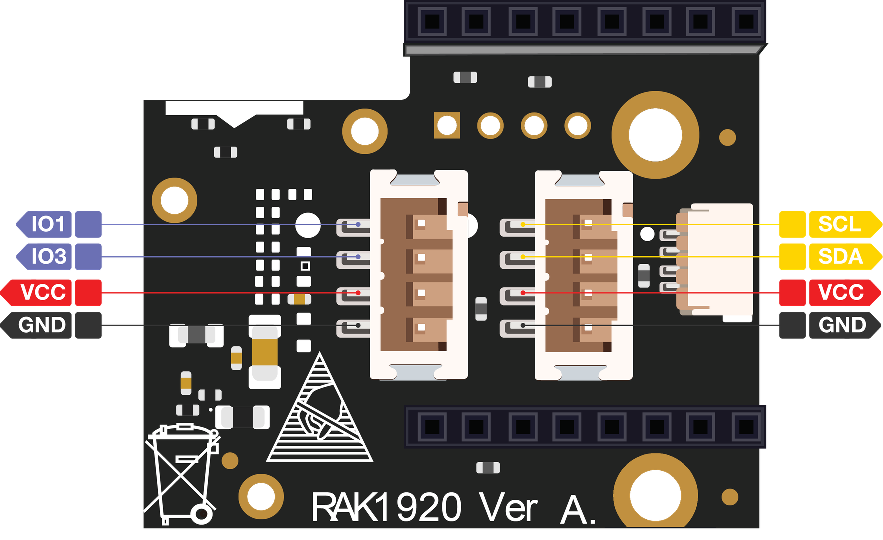 Figure 1: Grove Sensor interfaces
By default, the I2C is enabled in the RAK1920 module, but if it is required, the RAK1920 module can also support sensors with Grove UART interface and ADC sensors. To enable the UART interface, a resistance connection needs to be added by the customer. When using the Grove UART interface sensor module, replace R9 to R10 and R11 to R12. When using Grove ADC interface (not ADC to I2C module) sensor module, replace R13 to R14 and change R15 to R16.
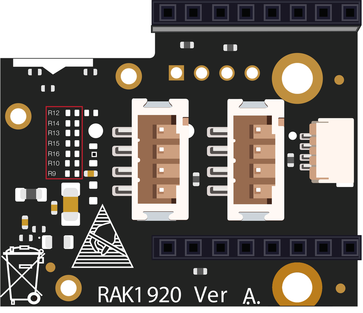 Figure 1: Replace connection resistance location
Figure 6 shows Grove sensor cables:
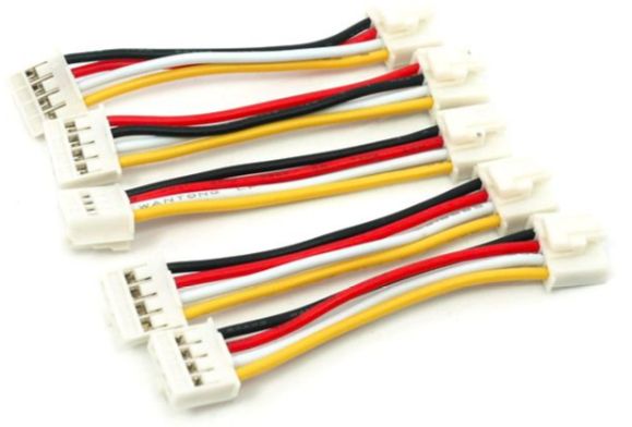 Figure 1: Grove Sensor cables
Table below shows Grove cable color and function definition.
| Pin | Color | Function |
|---|---|---|
| 1 | Yellow | Digital IO1 /ADC CH1 /UART RX /I2C Cock |
| 2 | White | Digital IO2 /ADC CH2 /UART TX /I2C Data |
| 3 | Red | VCC |
| 4 | Black | GND |
Qwiic Sensor Interface
The RAK1920 module supports sensors manufactured by SparkFun through the Qwiic Connect interface. Figure 7 shows the Qwiic Connect interface:
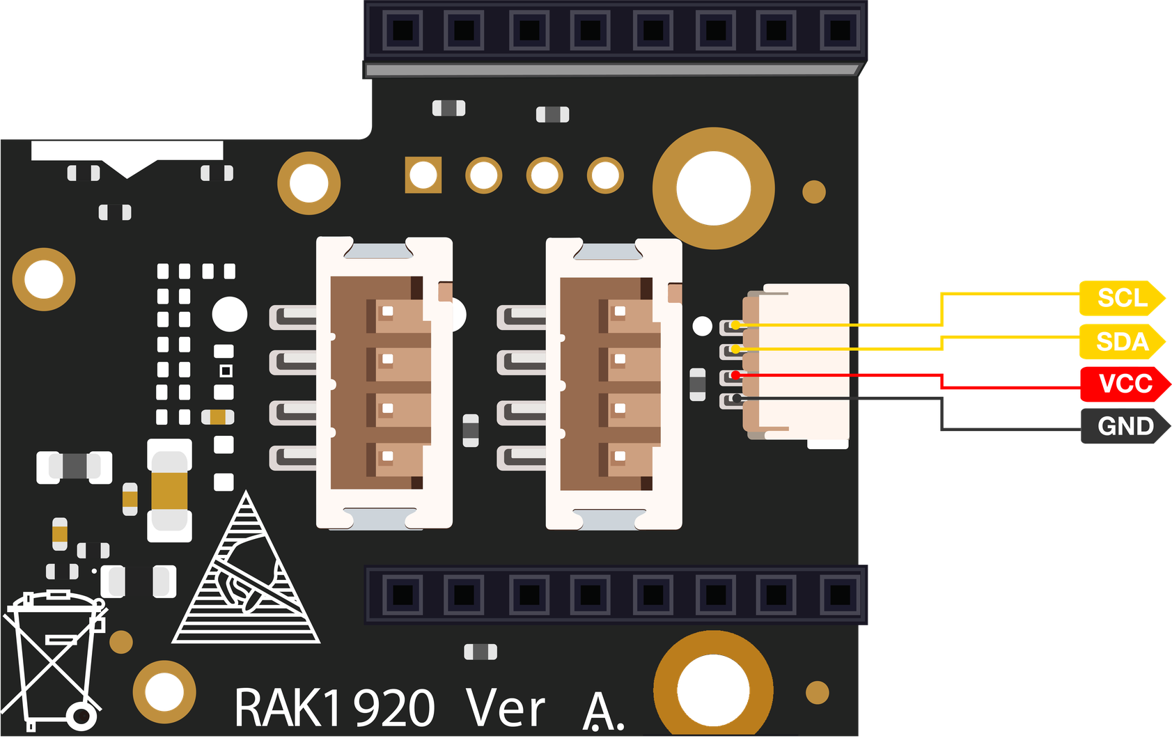 Figure 1: Qwiic Connect® interface
Figure 8 shows a Qwiic Connect cable:
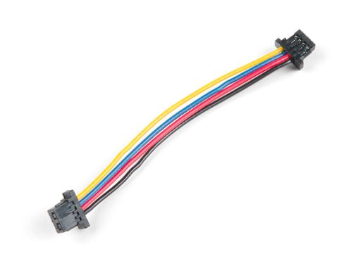 Figure 1: Qwicc Cable
The table below shows the Qwiic Connect cable color and function definition:
| Pin | Color | Function |
|---|---|---|
| 1 | Yellow | I2C Clock |
| 2 | Blue | I2C Data |
| 3 | Red | 3.3 V |
| 4 | Black | GND |
Reserved I2C Interface
The RAK1920 module has a reserved I2C interface, and it can be used for generic I2C interface sensors.
The I2C interface only supports 3.3 V type of sensors. The reversed I2C interface is shown in Figure 9.
 Figure 1: Reserved I2C Interface
Electrical Characteristics
Absolute Maximum Ratings
Table below shows the absolute maximum ratings of the RAK1920 module:
| Symbol | Description | Min. | Nom. | Max. | Unit |
|---|---|---|---|---|---|
| VBAT | Power supply for the module | -0.5 | 4.2 | V | |
| Iout | Boost converter output current | 50 | mA |
Recommended Operating Conditions
Table below shows the recommended operating conditions of the RAK1920 module:
| Symbol | Description | Min. | Nom. | Max. | Unit |
|---|---|---|---|---|---|
| VBAT | Power supply for the module | 2.6 | 4.2 | V | |
| 3V3 | 3.3 V power supply | 3.3 | V | ||
| 5V | 5.5 V power supply | 5.0 | V |
Mechanical Characteristics
Board Dimensions
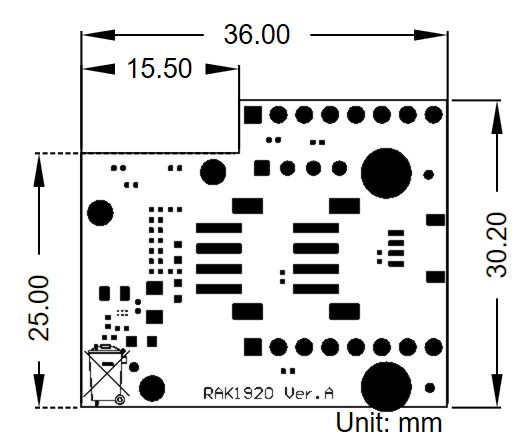 Figure 1: Mechanical Dimensions
WisConnector PCB Layout
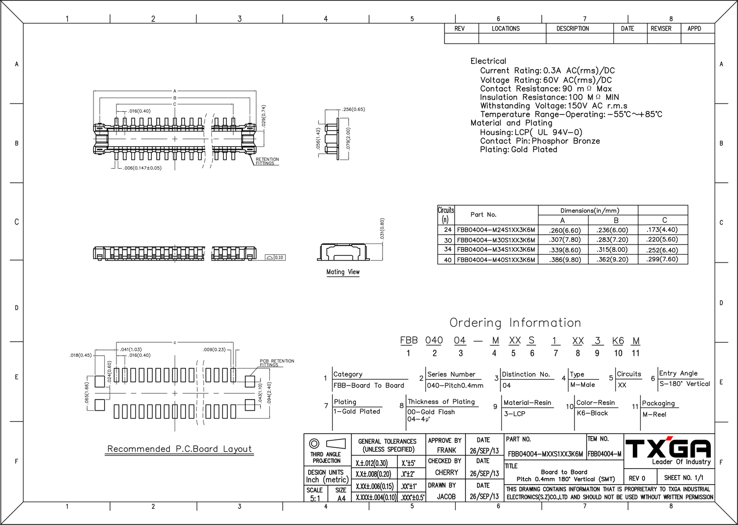 Figure 1: WisConnector PCB footprint and recommendations
Schematic Diagram
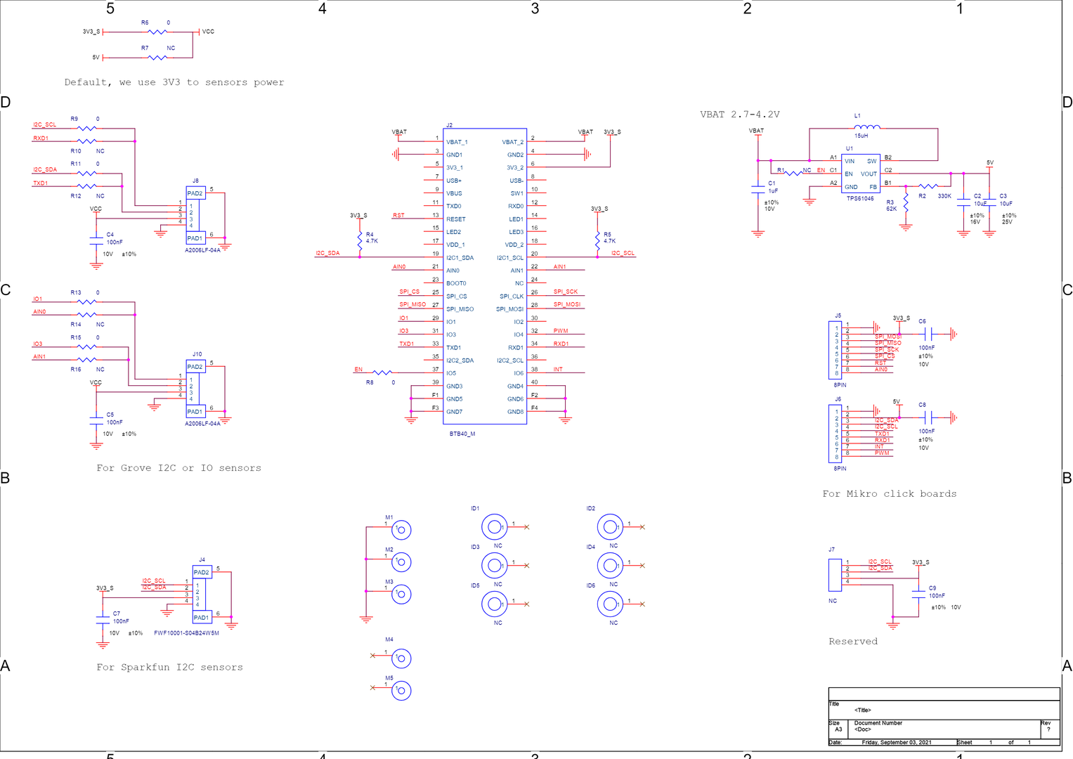 Figure 1: Schematic Diagram
The following sections will describe the schematic of the RAK1920 module:
- Power Supply
- IO Connector
Power Supply
The RAK1920 module supports the 5 V option. By default, the 3.3 V_S is used as the 3.3 V power source of sensors. The module integrates a boost converter from the VBAT to 5 V. The VBAT is the battery output voltage, usually between 3.7 V and 4.2 V. The EN pin enables the boost converter and is controlled by the WisBlock Core module of the overall solution.
The 3V3_S has to be enable via WB_IO2 GPIO. Otherwise, the module will not work.
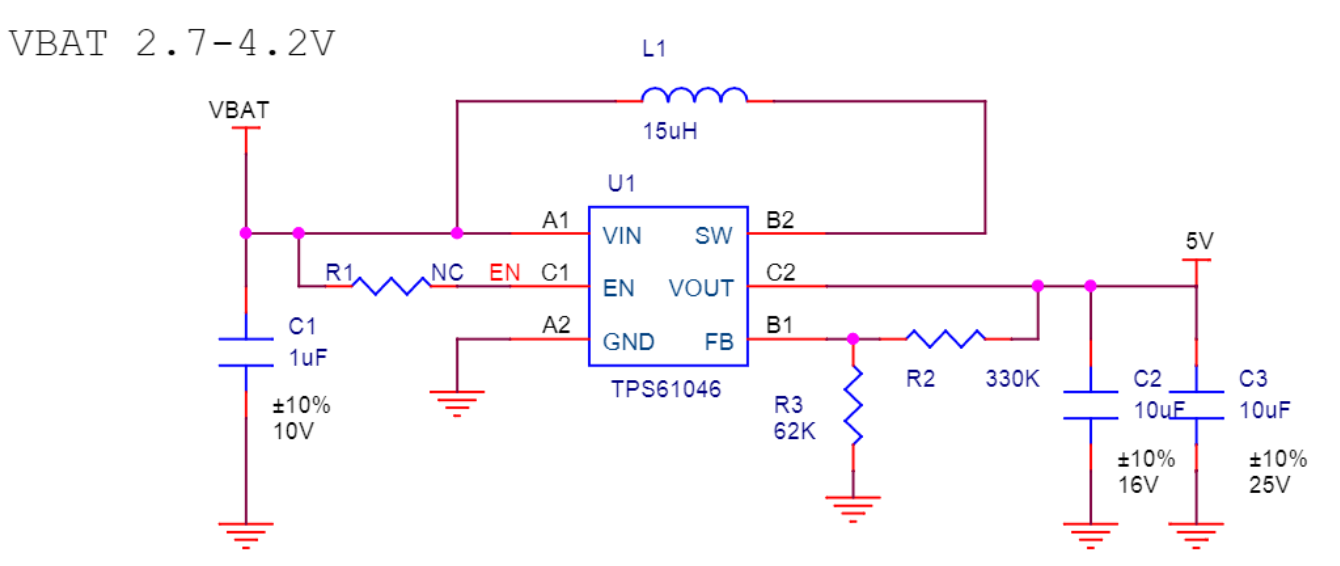 Figure 1: Power supply
IO Connector
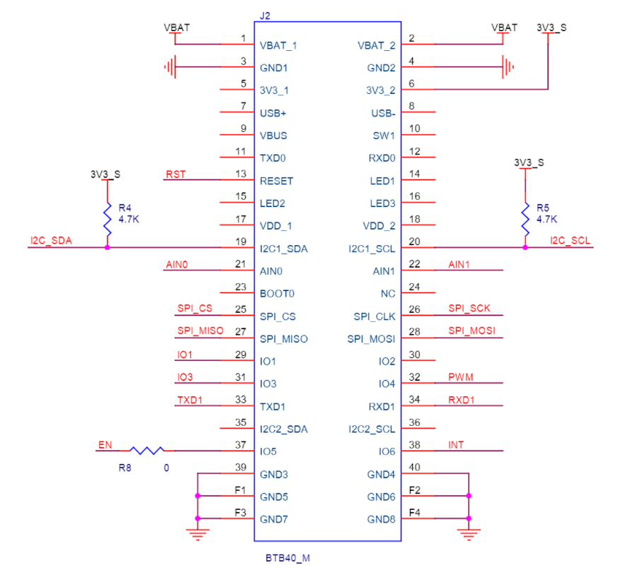 Figure 1: IO Connector
The RAK1920 module uses only a subset of all the pins available in the IO connector. These are shown in the table below:
| Name | Description | Comment |
|---|---|---|
| VBAT | Battery output voltage | Maximum: 4.2 V |
| 3V3 | 3.3 V | Default, sensor power supply |
| TXD1/RXD1 | UART interface | Connected only to the Click Boards connector. |
| CS/SCK/MOSI/MISO | SPI interface | Connected only to the Click Boards. |
| SDA/SCL | I2C interface | All I2C sensors |
| AIN0/AIN1 | ADC input interfaces | Grove or click Boards |
| INT | Hardware Interrupt | Connected only to the Click Boards connector. |
| RST | Reset | Connected only to the Click Boards connector. |
| PWM | PWM input | Connected only to the Click Boards connector. |
| EN | Boost Converter Enable | IO5 |
| IO1/IO3 | General purpose I/O | Connected to Grove digital I/O sensors’ connectors. |
IO Connector Pin Order
Figure 15 shows the IO connector’s pin order. The connector is located in the bottom layer of the RAK1920 module.
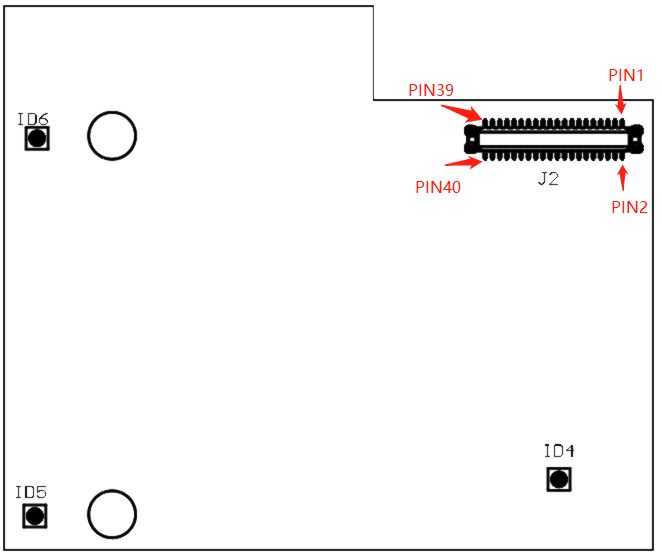 Figure 1: IO connector’s pin order