RAK3312 WisBlock LoRaWAN + BLE + WiFi Module Quick Start Guide
Prerequisites
Before going through each step in using the RAK3312 WisBlock Core, make sure to prepare the necessary items listed below:
Hardware
- RAK3312 WisDuo LPWAN+BLE+WiFi Module
- Computer
- Your choice of WisBlock Base
- Your choice of WisBlock Modules
- USB Cable
- Li-Ion/LiPo battery (optional)
- Solar charger (optional)
Software
- Download and install the Arduino IDE.
- Install the Espressif ESP32 BSP in Arduino following the guide Installing Arduino-ESP32 support.
The RAK3312 is supported by the official Espressif BSP as RAKwireless RAK3112 board.
If you are using Windows 10. Do NOT install the Arduino IDE from the Microsoft App Store. Instead, install the original Arduino IDE from the Arduino official website. The Arduino app from the Microsoft App Store has problems using third-party Board Support Packages.
Using the RAK3312 with PlatformIO
Solution to use the RAK3312 with the ESP32 platform in PlatformIO (temporary)
To use the RAK3312 with PlatformIO and the ESP32 platform, a custom project structure is required. This includes an additional folder in the project folder and some extra entries in the platformio.ini file of the project.
- Download the folder rakwireless from our GitHub repo
- Copy this folder into your project folder.
Your project folder should look like this:
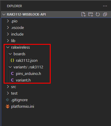 Figure 1: RAK3312 Board definition in PlatformIO project folder
- Add the following entries to the platformio.ini file of your project:
[platformio]
default_envs = rak3112
description = RAK3312
boards_dir = rakwireless/boards

[env:rak3112]
framework = arduino
platform = platformio/espressif32
board = rak3112

build_flags = -I rakwireless/variants/rak3112
boards_dir = rakwireless/boardstells PlatformIO where to find additional boards for the ESP32 platform.board = rak3112tells PlatformIO to use the custom board rak3112 from the additional boards folder.build_flags = -I rakwireless/variants/rak3112tells PlatformIO where to findpins_arduino.handvariant.hfiles for the board RAK3312.
Keep these entries in the platformio.ini file and add your other definitions, e.g. lib_deps or additional build_flags.
Product Configuration
Hardware Setup
RAK3312 to WisBlock Base
The RAK3312 will not work without a WisBlock Base board. The WisBlock Base provides a USB connection for programming the RAK3312. It also provides a power source and various interfaces to RAK3312 so that it can be connected to other WisBlock Modules via different module slots.
RAKwireless offers many WisBlock Base Boards compatible with WisBlock Core. It is highly recommended that you review these WisBlock Base boards to see what matches your requirements in terms of available module slots, power supply options, and overall size.
To illustrate, RAK3312 can be connected to RAK19007 WisBlock Base, as shown in Figure 1.
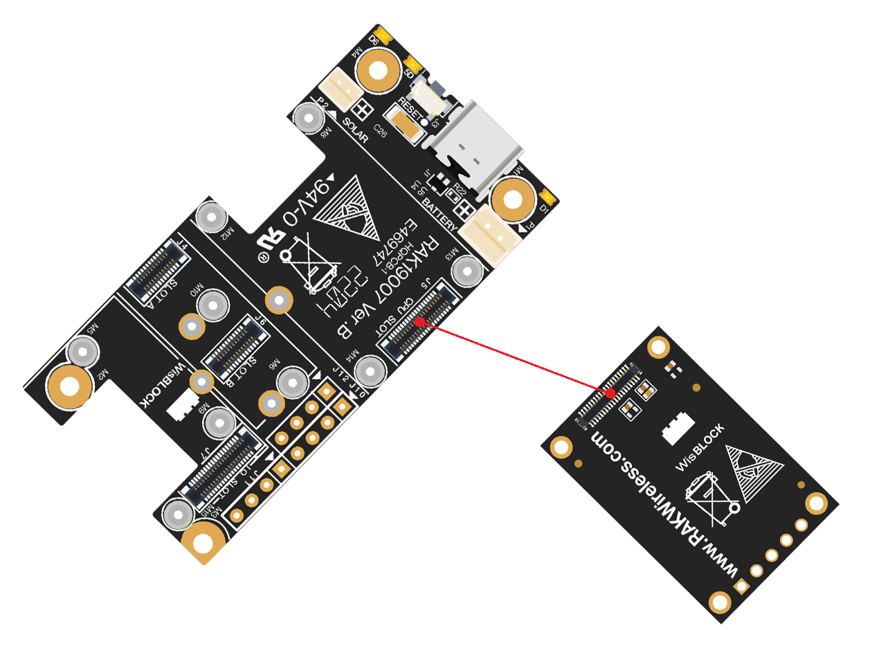 Figure 1: RAK3312 Connection to WisBlock Base RAK19007
Few pins are exposed on RAK19007, and you can easily use them via header pins. The labels are at the back, as shown in Figure 2.
 Figure 1: WisBlock Base exposed pins
More information can be found on the official documentation of the specific WisBlock Base you used in your project.
For RAK19007 WisBlock Base with RAK3312 WisBlock Core, the accessible GPIO pins are defined as follows in the Arduino IDE and Platform IO:
WB_IO1for IO1 pinWB_IO2for IO2 pin (Also used to control the 3.3 V supply of some WisBlock Modules to achieve low-power IoT devices.)WB_A0for AIN
There are usable LEDs as well that can be controlled by the RAK3312 on the WisBlock Base board:
LED_GREENLED_BLUE
I2C_1 is also exposed on the header of the WisBlock Base board.
- The I2C interface of the RAK3312 is exposed through the I2C_1 header pins, which are also shared with WisBlock Base Slots A-D.
RAK3312 to WisBlock Modules
RAK3312 WisBlock Core is designed to be interfaced with other WisBlock Modules like sensors, displays, and other interfaces. You need to connect these modules to the compatible slots on the WisBlock Base.
Each WisBlock Modules that will be used with RAK3312 WisBlock Core have a dedicated quick start guide you can follow on how to connect to the WisBlock Base.
Listed are the quick start guide of some WisBlock modules you can buy from our store:
The listed links are just examples. All WisBlock Modules have their own quick start guide that you can use as a reference to get started on specific modules.
Figure 3 shows an illustration on how you can combine various WisBlock Modules with the RAK3312 WisBlock Core via the WisBlock Base board.
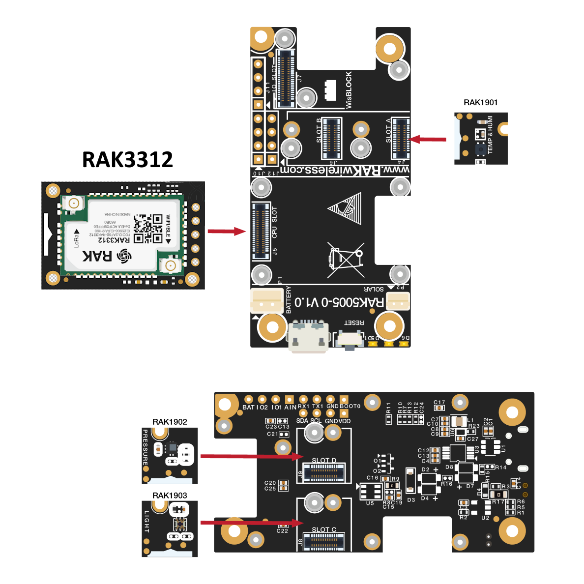 Figure 1: RAK3312 Connection to WisBlock Base and other WisBlock Modules
Assembling and Disassembling of WisBlock Modules
Assembling
Figure 4 shows how to mount the RAK3312 module on top of a WisBlock Base board (RAK19007). Follow carefully the procedure defined in WisBlock module assembly/disassembly instructions in order to secure the connection safely. Once attached, carefully fix the module with one or more pieces of M1.2 x 3 mm screws depending on the module.
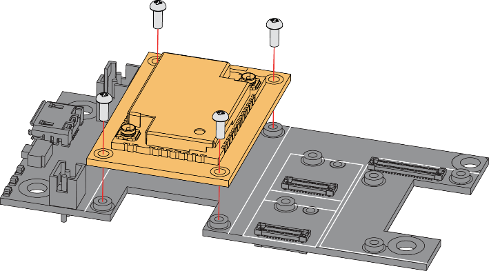 Figure 1: RAK3312 Mounting Sketch
Disassembling
The procedure in disassembling any type of WisBlock module is the same.
- First, remove the screws.
 Figure 1: Removing screws from the WisBlock module
- Once the screws are removed, check the silkscreen of the module to find the correct location where force can be applied.
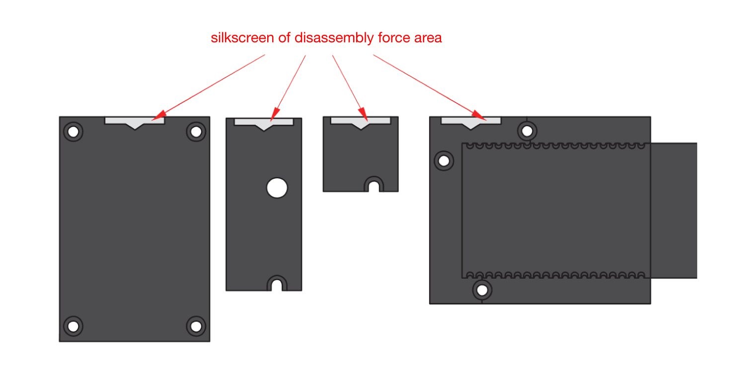 Figure 1: Detaching silkscreen on the WisBlock module
- Apply force to the module at the position of the connector, as shown in Figure 7, to detach the module from the baseboard.
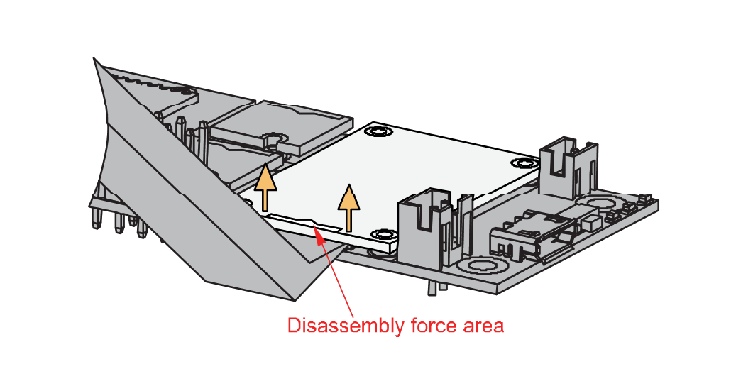 Figure 1: Applying even forces on the proper location of a WisBlock module
LoRa and WiFi/BLE Antenna
Another important components of the RAK3312 are the antennas.
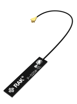 Figure 1: LoRa Antenna
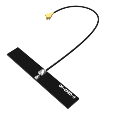 Figure 1: BLE/WiFi Antenna
You need to ensure that these antennas are properly connected to have a good LoRa and BLE signal. Also, note that you can damage the RF section of the chip if you power the module without an antenna connected to the IPEX connector.
RAK3312 has a label on its sticker where to connect the antennas, as shown in Figure 10.
 Figure 1: RAK3312 antenna label
- Detailed information about the RAK3312 LoRa IPEX MHF4 antenna can be found in the 863-870 MHz antenna datasheet or the 902-928 MHz antenna datasheet.
- Standard IPEX connector will not work on RAK3312. The IPEX antenna connectors of RAK3312 are a different variant called IPEX MHF-4. This is specially designed for low-profile circuit boards with limited spaces.
- When using the LoRa, WiFi or Bluetooth Low Energy transceivers, make sure that the antennas are connected. Using these transceivers without an antenna can damage the module.
Battery and Solar Connection
RAK3312 can be powered via the USB cable or Li-Ion/LiPo battery via the dedicated connectors, as shown in Figure 11. The matching connector for the battery wires is a JST PHR-2 2 mm pitch female.
This illustration uses RAK19007 as WisBlock Base. There are other WisBlock Base boards available, and you need to check the datasheet of the specific WisBlock Base board for the right polarity and other parameters.
- Batteries can cause harm if not handled properly.
- Only 3.7-4.2 V Rechargeable LiPo batteries are supported. It is highly recommended not to use other types of batteries with the system unless you know what you are doing.
- If a non-rechargeable battery is used, it has to be unplugged first before connecting the USB cable to the USB port of the board to configure the device. Not doing so might damage the battery or cause a fire.
- Only 5 V solar panels are supported. Do not use 12 V solar panels. It will destroy the charging unit and eventually other electronic parts.
- Make sure the battery wires match the polarity on the WisBlock Base board. Not all batteries have the same wiring.
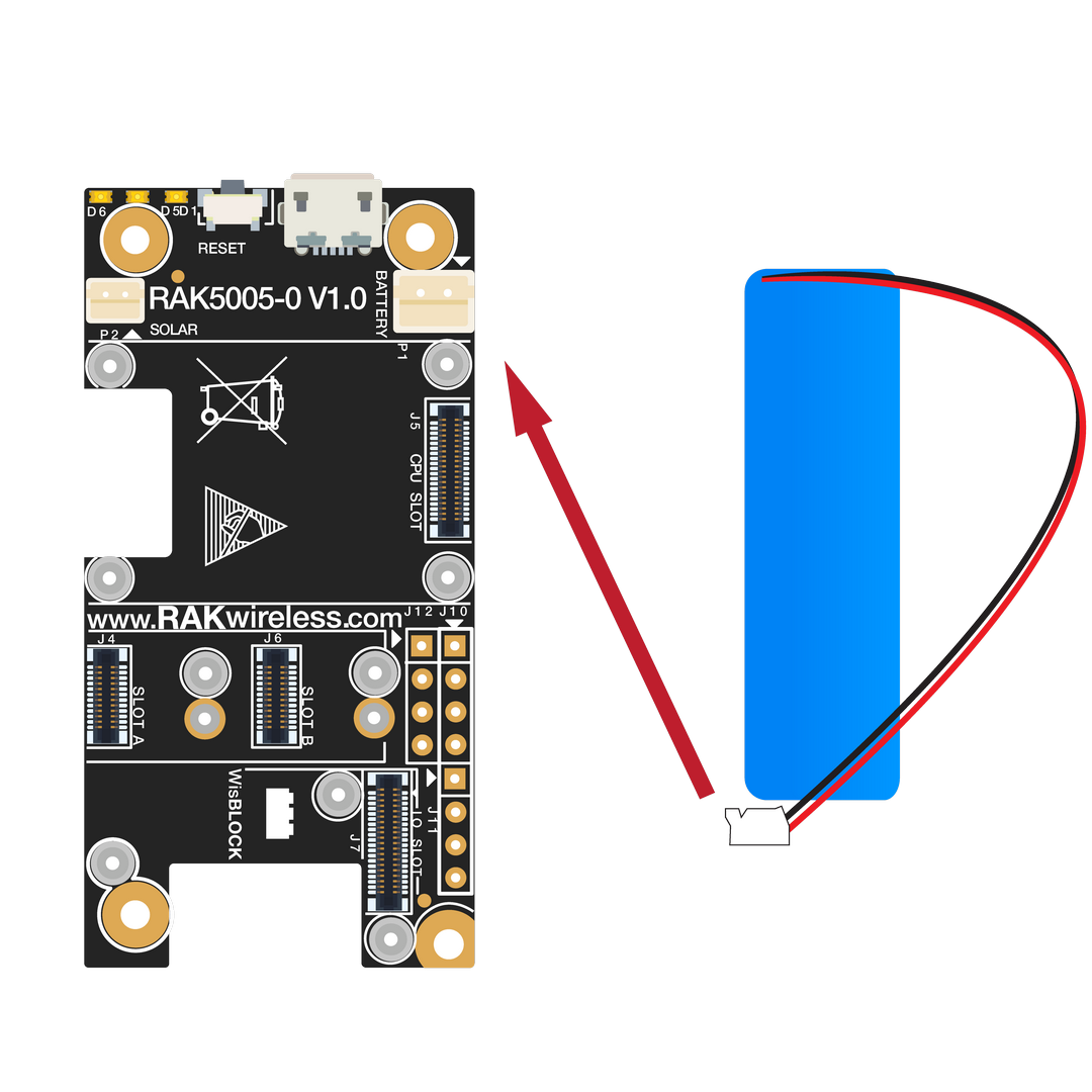 Figure 1: WisBlock Base connection
 Figure 1: Battery connection
The battery can be recharged as well via small solar panel, as shown in Figure 13. The matching connector for the solar panel wires is an JST ZHR-2 1.5 mm pitch female.
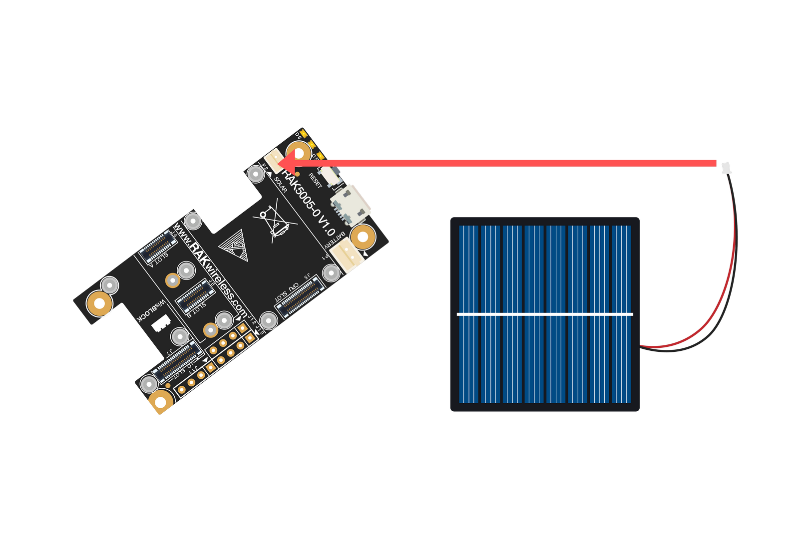 Figure 1: Solar panel connection
Specification of the battery and solar panel can be found on the datasheet of the WisBlock Base.
Software Setup
The RAK3312 WisBlock Core is designed to be interfaced with other WisBlock Modules like sensors, displays, and other interfaces. To make useful devices, you need to upload a source code to the RAK3312.
Before you continue, you should have either the Arduino BSP or Platform IO already setup.
RAK3312 Example Repository
To quickly build your IoT device with less friction, example codes for RAK3312 to be used on all WisBlock Modules are provided.
You can access the codes on the WisBlock Example code repository. The example codes compatible only with RAK3312 are in the folders RAK3312. The shared examples of the WisBlock Core are in the common folder.
To use these examples, you have two options: Arduino IDE or Platform IO.
Compile an Example with Arduino
After adding the RAK3312 to the Arduino IDE, test your setup by running a simple program.
- Copy the example code below and paste it into the Arduino IDE.
Click to view the example code.
void setup() {
  Serial.begin(115200);
}

void loop() {
  Serial.println("Hello");
  delay(5000);
}
 Figure 1: Example code
- Click the Verify button to compile and check for errors.
 Figure 1: Verify the example code
- When the compilation is complete, click the Upload button to flash the firmware to the RAK3312.
 Figure 1: Upload the example code
- Upon successful upload, the Device programmed message will appear.
 Figure 1: Device Programmed
- After the Device Programmed is completed, you will see the "Hello" message every 5 seconds in the console.
 Figure 1: Application log output
LoRaWAN Example
This example illustrates how to program the RAK3312 as a stand-alone LoRaWAN end device via Arduino APIs and the SX126x-Arduino library. To use the RAK3312 as a LoRaWAN end device, it must be within reach of a working LoRaWAN gateway registered to a LoRaWAN network server (LNS) or with a built-in network server.
If you are new to LoRaWAN, here are a few good references about LoRaWAN and gateways:
To enable the RAK3312 module as a LoRaWAN end-device, a device must first be registered with the LoRaWAN network server. This guide covers both TTN and ChirpStack LoRaWAN network servers and the associated Arduino codes and AT commands for the RAK3312.
- The Things Network Guide: How to login, register new accounts, and create new applications on TTN.
- RAK3312 TTN OTAA Guide: How to add OTAA device on TTN and what AT commands to use on RAK3312 OTAA activation.
Connect with The Things Network (TTN)
This section shows how to connect the RAK3312 module to the TTN platform.
A working gateway connected to TTN is required, or the device must be within the coverage of a TTN community network.
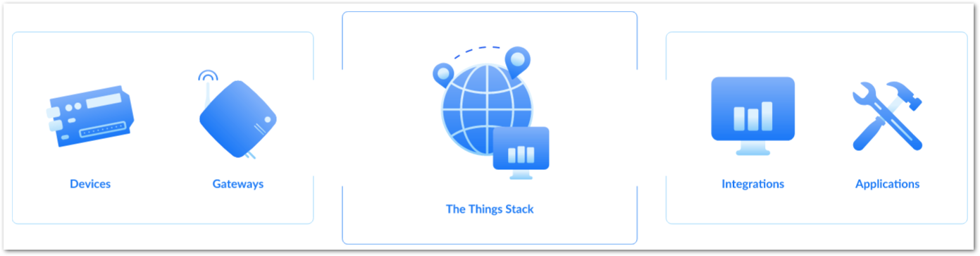 Figure 1: The Things Stack
As shown in Figure 22, The Things Stack (TTN V3) is an open-source LoRaWAN network server suitable for global, geo-distributed public and private deployments as well as for small local networks. The architecture follows the LoRaWAN Network Reference Model for standards compliance and interoperability. This project is actively maintained by The Things Industries.
LoRaWAN is a protocol for low-power wide-area networks. It allows large-scale Internet of Things deployments where low-powered devices efficiently communicate with internet-connected applications over long-range wireless connections.
The RAK3312 WisDuo module can be part of this ecosystem as a device, and the objective of this section is to demonstrate how simple it is to send data to The Things Stack using the LoRaWAN protocol. To achieve this, the RAK3312 WisDuo module must be located within the coverage of a LoRaWAN gateway connected to The Things Stack server.
- Sign up for a TTN account.
a. Go to The Things Network and click on Sign up.
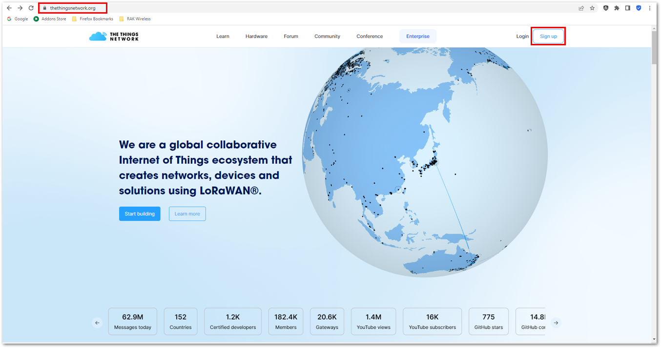 Figure 1: Sign up an account in TTN
b. Select a community type by clicking Get started.
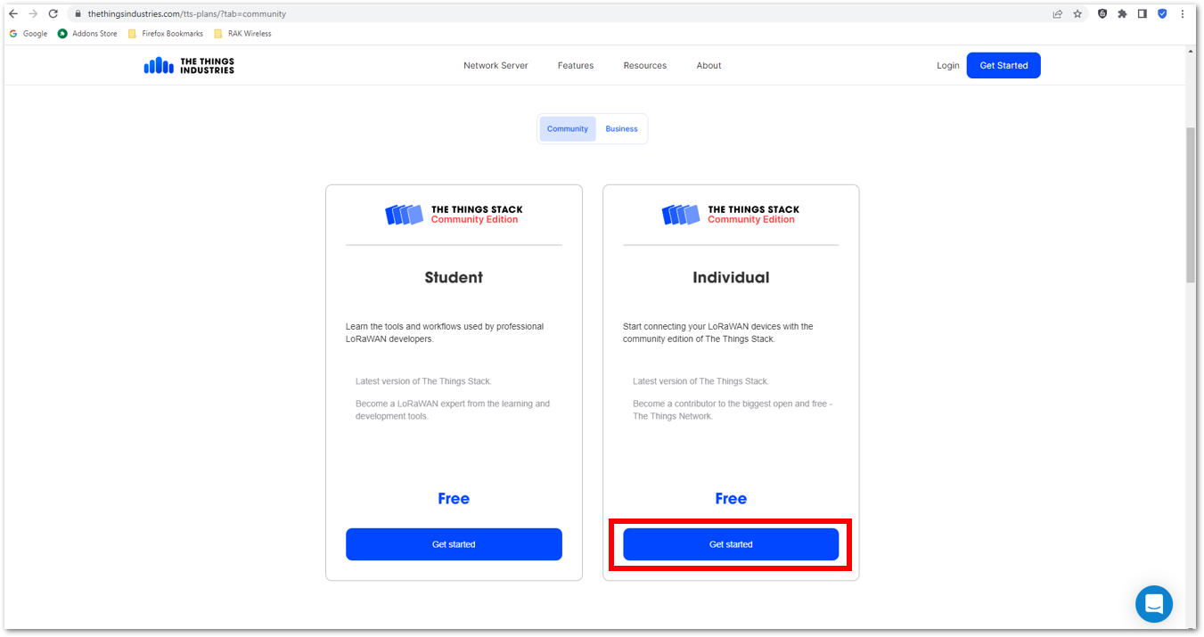 Figure 1: TTN community type
c. Sign up through The Things ID by clicking Sign up for free.
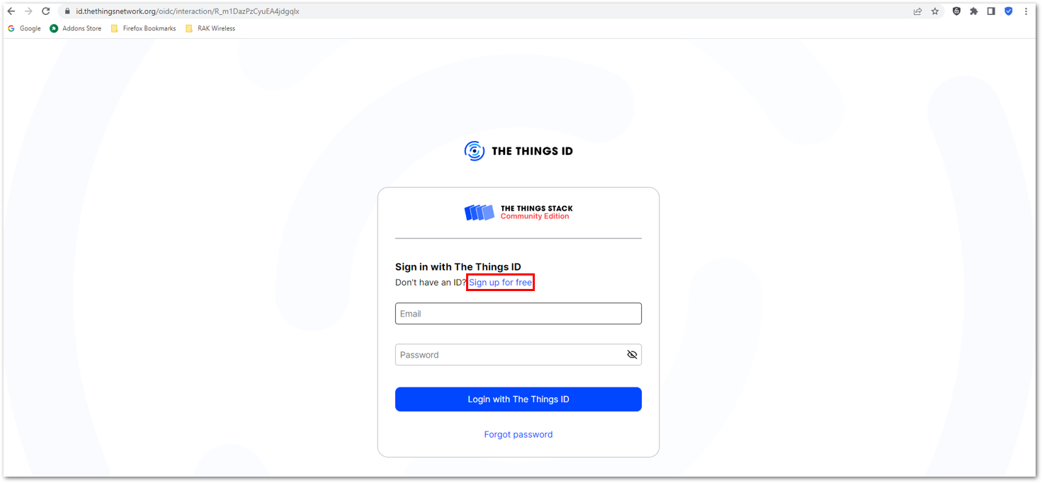 Figure 1: Sign up through The Things ID
d. Enter your details, agree to the Terms and Conditions, and click Sign up to The Things ID.
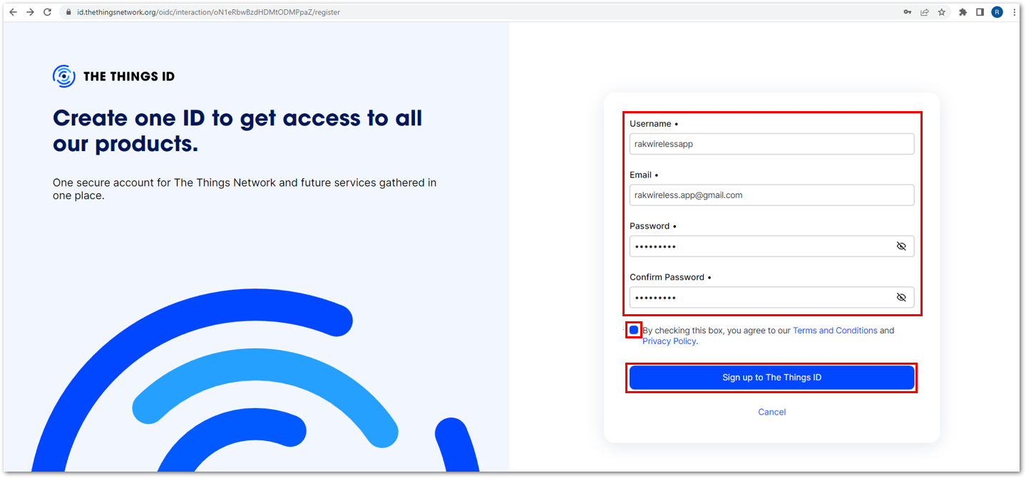 Figure 1: Enter account details
e. Then, select a cluster as shown in Figure 27.
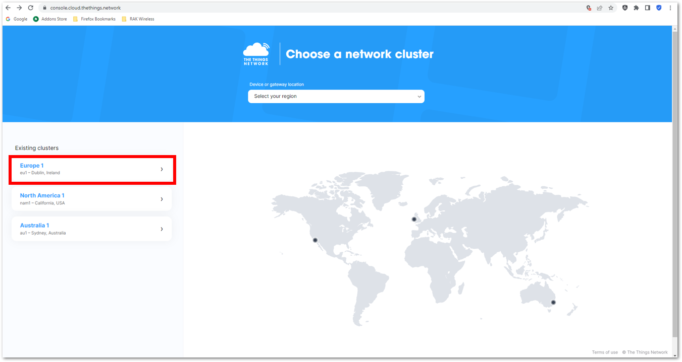 Figure 1: Select a cluster in TTN
Use the same login credentials on the TTN V2 if you have one. If you have no account yet, create one.
- Once logged in to the platform, create an application by clicking Create an application.
 Figure 1: Create a TTN application for your LoRaWAN devices
- Navigate to the Applications tab.
 Figure 1: Details of the TTN application
- Fill in the necessary information about your application, then click Create application.
 Figure 1: TTN application
If you had no errors in the previous step, the application console page should now be visible. The next step is to add end-devices to your TTN application.
LoRaWAN specifications enforce that each end-device has to be personalized and activated. There are two options for registering devices, depending on the activation mode selected. Activation can be done either via Over-The-Air-Activation (OTAA) or Activation-By-Personalization (ABP).
TTN OTAA Device Registration
- Go to your application console to register a device. To start adding an OTAA end-device, click +Register end device, as shown in Figure 29.
 Figure 1: Register OTAA end-device
- Register the board by selecting Enter end device specifics manually.
 Figure 1: Enter OTAA end-device specifics manually
- Configure the Frequency plan, compatible LoRaWAN version, and supported Regional Parameters version.
 Figure 1: OTAA Frequency plan setup
 Figure 1: OTAA LoRaWAN version setup
 Figure 1: OTAA LoRaWAN Regional Parameters version setup
- Set the JoinEUI.
 Figure 1: OTAA JoinEUI setup
- Click Show advanced activation, LoRaWAN class and cluster settings.
 Figure 1: OTAA Show advanced activation
- Configure the following, then click Confirm.
- Activation mode: Over the air activation (OTAA)
- Additional LoRaWAN class capabilities: None (class A only)
 Figure 1: OTAA LoRaWAN class and cluster settings
- Once completed, push the Confirm button and enter the device's JoinEUI credential.
- The AppEUI (Join EUI), DevEUI, and AppKey are hidden in this section as these are unique to a specific device. The DevEUI is specific to every RAK3312 device, while the AppEUI and AppKey should be generated individually for each device and application.
- The AppEUI is the same as JoinEUI.
 Figure 1: OTAA DevEUI credential
- Click Generate under AppKey, as shown in Figure 39.
 Figure 1: OTAA AppKey credential
- Once done, click Register end device to complete the process.
 Figure 1: Click Register end device
After completing the device registration, the device should appear on the TTN console, as shown in Figure 40.
- The AppEUI (Join EUI), DevEUI, and AppKey are the parameters required to activate your LoRaWAN end-device via OTAA.
- The three OTAA parameters on the TTN device console are MSB by default.
- These parameters are always accessible on the device console page, as shown in Figure 40.
 Figure 1: OTAA end-device successfully registered to TTN
Upload OTAA LoRaWAN Example to RAK3312
After successfully registering the RAK3312 device to the LoRaWAN Network Server, proceed with running the RAK3112_OTAA demo application example.
- Get the example code from RAK3112_OTAA. Copy the code into the Arduino IDE sketch.
 Figure 1: OTAA LoRaWAN application example
- In the example code, modify the device EUI (DevEUI) and application key (AppKey).
- The DevEUI must match the one registered on your network server. This is the same DevEUI in the RAK3312 sticker if this is the one you used in Step 7 of the TTN OTAA Device Registration section. The DevEUI uses is MSB format.
// OTAA Device EUI MSB
uint8_t nodeDeviceEUI[8] = {0xac,0x1f,0x09,0xff,0xfe,0x00,0x00,0x00};
- The AppEUI (Join EUI) must match the one registered on your network server as well.
// OTAA Application Key MSB
uint8_t nodeAppEUI[8] = {0x70,0xB3,0xD5,0x7E,0xD0,0x02,0x01,0xE1};
- Another important parameter to update is the AppKey, which must match the one configured on your network server in Step 8 of the TTN OTAA Device Registration. The AppKey must be in MSB format.
// OTAA Application Key MSB
uint8_t nodeAppKey[16] = {0x2b,0x84,0xe0,0xb0,0x9b,0x68,0xe5,0xcb,0x42,0x17,0x6f,0xe7,0x53,0xdc,0xee,0x79};
 Figure 1: Update the OTAA, DevEUI, and AppKey
- Update the band in the code according to your region. This guide uses AS923-3 as an example, so no changes are needed if you're using the same band.
RAK3312 supports the following regions (based on definition in SX126x-Arduino library):
- LORAMAC_REGION_EU433 = 4
- LORAMAC_REGION_CN470 = 2
- LORAMAC_REGION_RU864 = 12
- LORAMAC_REGION_IN865 = 7
- LORAMAC_REGION_EU868 = 5
- LORAMAC_REGION_US915 = 8
- LORAMAC_REGION_AU915 = 1
- LORAMAC_REGION_KR920 = 6
- LORAMAC_REGION_AS923 = 0
- LORAMAC_REGION_AS923_2 = 9
- LORAMAC_REGION_AS923_3 = 10
- LORAMAC_REGION_AS923_4 = 11
Additionally, for US915, configuring the channel mask is necessary, with channels 8 to 15 being the most commonly used in this band.
The LoRaWAN region is set in the lmh_init() call:
lmh_init(&lora_callbacks, lora_param_init, true, CLASS_A, LORAMAC_REGION_AS923_3);
- The last step is to upload the code by clicking the Upload icon. Take note that you should select the right board and port.
Figure 1: Upload the OTAA example codeThe terminal logs should now be visible in the Serial Monitor of the Arduino IDE. If the COM port disconnects, the terminal output may not appear immediately. Reconnecting the module or pressing the reset button can help restore the output.
 Figure 1: Terminal logs
- Check the Live data section on the LoRaWAN network server to see if the device has successfully joined with the
join requestandjoin acceptlogs.
 Figure 1: OTAA live data on TTN
Arduino Installation
Refer to Software section.