RAK5801 WisBlock 4-20mA Interface Module Quick Start Guide
Prerequisite
What Do You Need?
Before going through each and every step on using the RAK5801 WisBlock module, make sure to prepare the necessary items listed below:
Hardware
- RAK5801 WisBlock 4-20mA Interface Board
- WisBlock Base
- Your choice of WisBlock Core
- USB Cable
- Li-Ion/LiPo battery (optional)
- Solar charger (optional)
Software
Arduino
- You need to download and install Arduino IDE.
- To add the RAKwireless Core boards on your Arduino Boards Manager, install the RAKwireless Arduino BSP.
Product Configuration
Block Diagram
The RAK5801 module was designed to convert 4-20 mA current signals into voltage signals by applying a sampling resistor. As shown in Figure 1, the input current signal from the sensor is conditioned by an operational amplifier to match the level supported by the ADC input of an MCU where the signal is digitized.
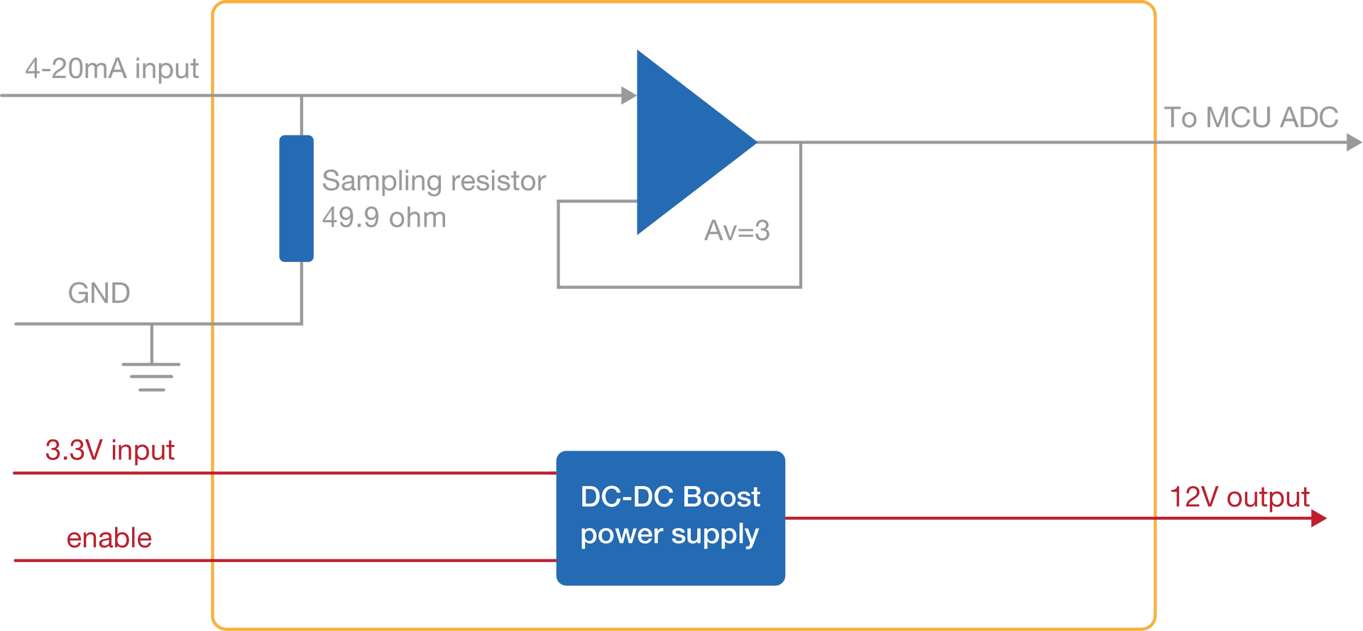 Figure 1: RAK5801 Block Diagram
Once the signal is digitalized, the user can recover the original current value by applying the following formula:
I = U/149
Where U is the ADC reading and I is the sensor current.
As shown in Figure 1, the module provides an output of 12 V for powering passive 4-20 mA sensors. This 12 V output is boosted by an internal DC-DC booster. The enable pin allows to control the power conversion module and set the RAK5801 module into a low-power consumption mode.
Hardware Setup
The RAK5801 is a 4-20 mA current loop extension module that allows you to make an IoT solution for analog sensors with 4-20 mA interface. This module converts the 4-20 mA current signal into voltage range supported by the WisBlock Core module for further digitalization and data transmission. This module integrates a 12 V power supply, which can be used to power external sensors. The RAK5801 can be connected to 2-wire, 3-wire, or 4-wire types of 4-20 mA sensor. For more information about RAK5801, refer to the Datasheet.
Installation
Mounting Mechanism
The RAK5801 module is part of the WisBlock Interface category, which connects to the baseboard through the IO slot. The installation method is shown in Figure 2 and Figure 3.
- Keep the RAK5801 module parallel to the baseboard, and gently place and plug WisConnector into the IO slot receptacle of the baseboard. The IO slot has an outer silkscreen on it to assist with the alignment. At this point, apply force evenly along with the module and press again. There will be a sound to confirm the successful completion of the attachment process.
For detailed instructions, refer to the WisBlock Installation Guide.
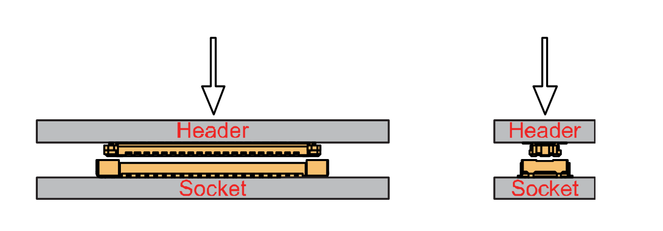 Figure 1: WisConnector
- Always secure the RAK5801 module with 3 x M1.2 x3 pan head screws, as shown in Figure 3.
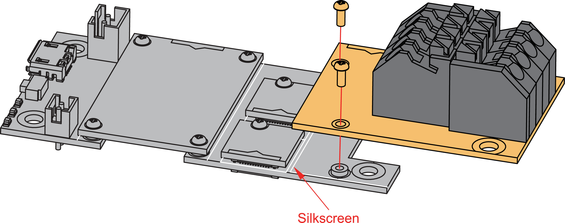 Figure 1: RAK5801 mounting mechanism on a WisBlock Base module
RAK5801 Fast Crimping Terminal Mechanism
The RAK5801 features a fast-crimping terminal connector to simplify and ensure the wiring process on the fields. The fast-crimping terminal can support cable with a width between 20 AWG to 24 AWG. The usual stripping length is around 6 to 7 mm.
As shown in Figure 4, during the crimping process, you should first press down and maintain the spring head of the crimping terminal firmly, then insert the stripped cable head into the corresponding connector’s hole. Once inserted correctly, then release the spring head, and the crimping process is completed.
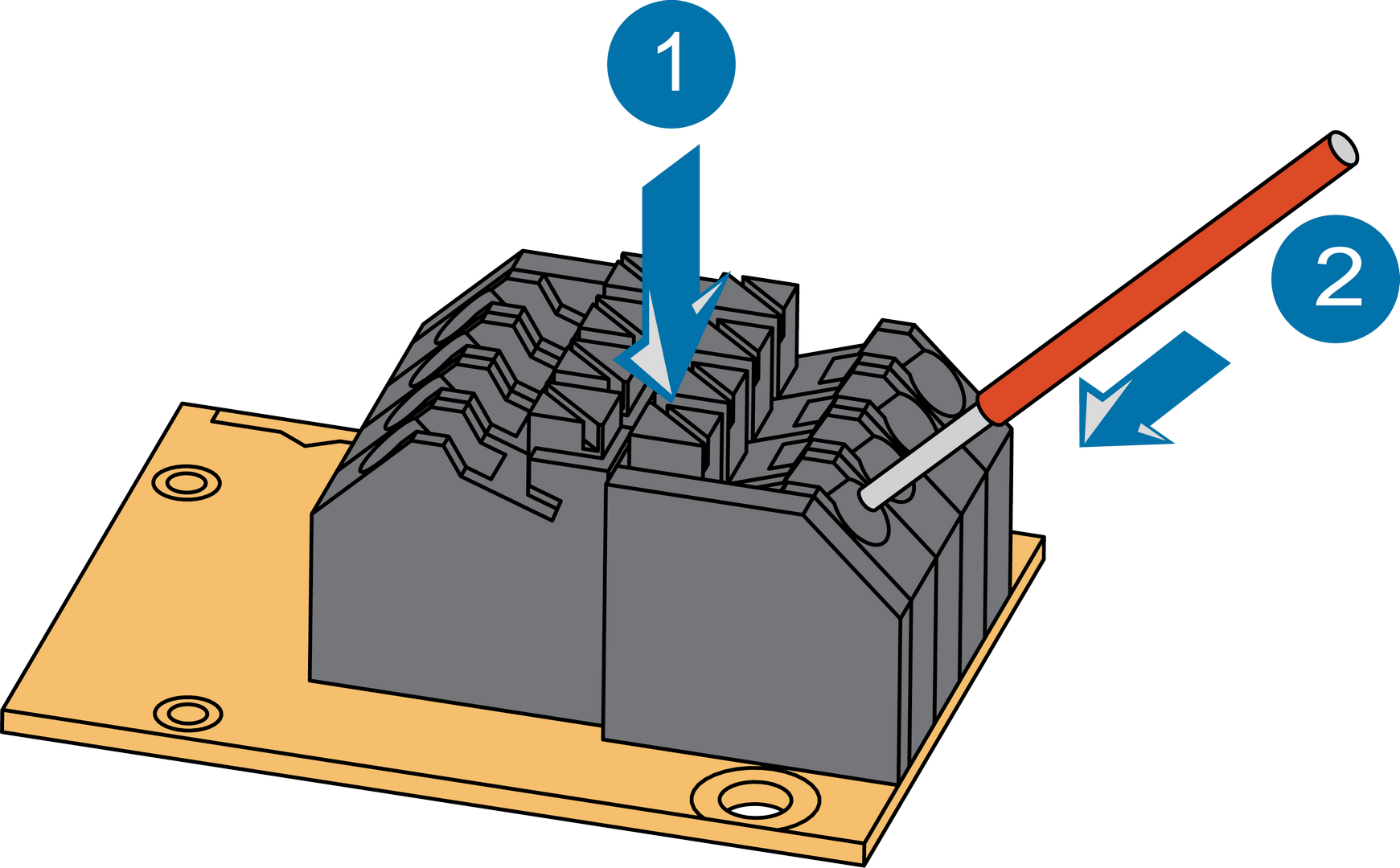 Figure 1: RAK5801 Sensor Connector
Disassembling Procedure
The procedure in disassembling any type of WisBlock module is the same.
- Remove the screws.
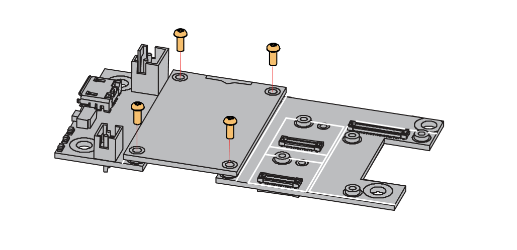 Figure 1: Removing screws from the WisBlock module
- Once the screws are removed, check the silkscreen of the module to find the correct location where force can be applied.
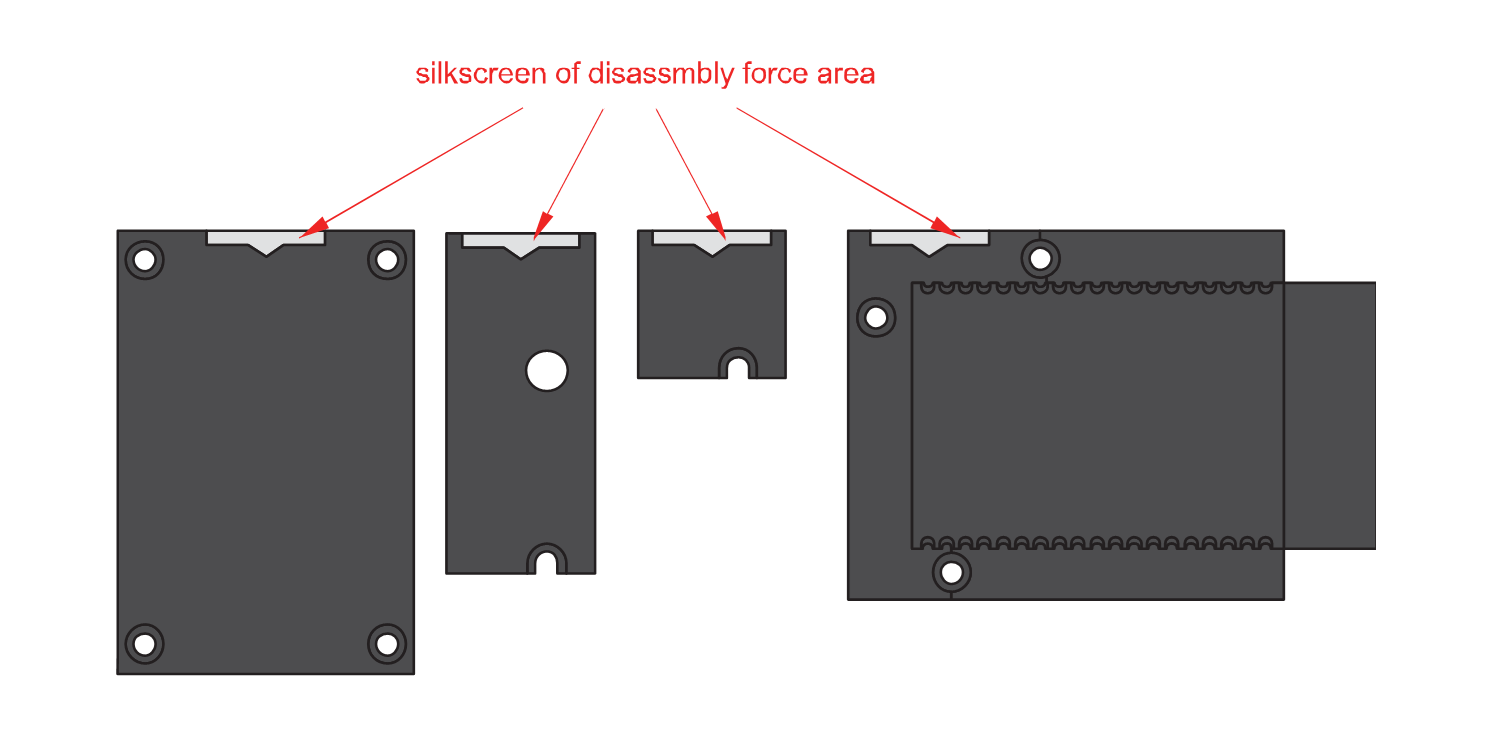 Figure 1: Detaching silkscreen on the WisBlock module
- Apply force to the module at the position of the connector, as shown in Figure 7, to detach the module from the baseboard.
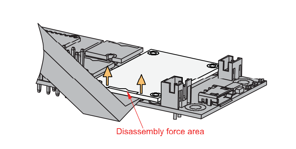 Figure 1: Applying even forces on the proper location of a WisBlock module
If you will connect other modules to the remaining WisBlock Base slots, check on the WisBlock Pin Mapper tool for possible conflicts.
Pin Definition
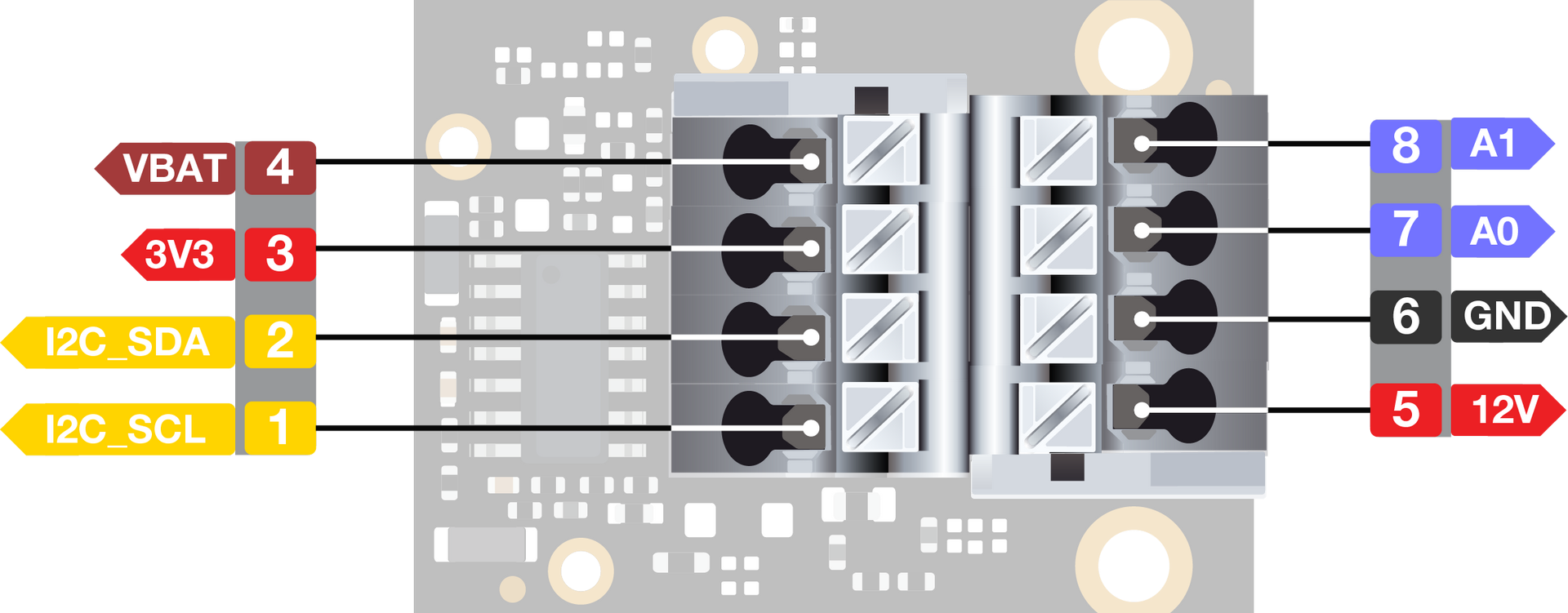 Figure 1: RAK5801 Pin Definition
Typical Application
Two-Wire sensor
Two-wire transmitters are energized by the current loop, where the supply voltage is included in the receptor. The transmitter is floating and the ground is in the receptor.
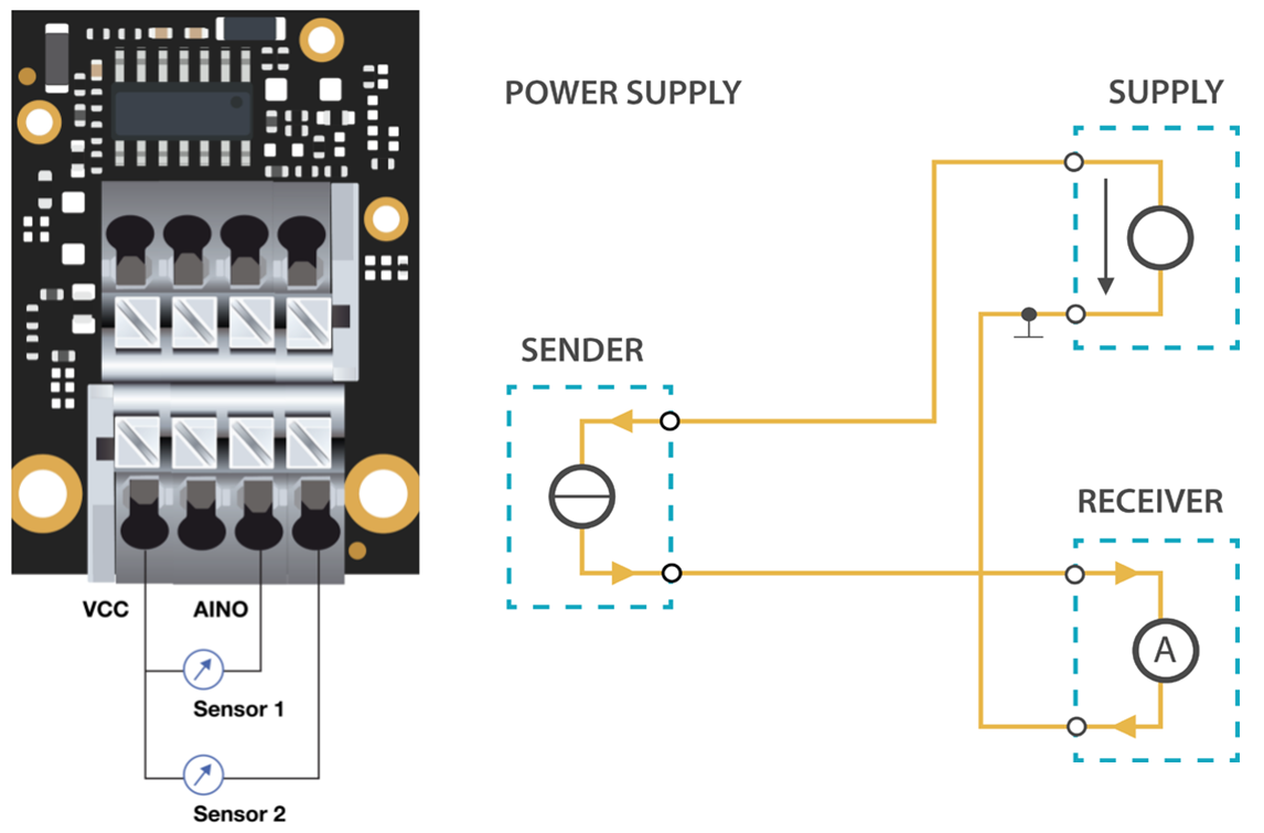 Figure 1: RAK5801 with 2-wire/4-20mA sensor
Three-Wire Sensor
Three-wire transmitters have three wires powered by the source voltage in them. In this case, the transmitter is the power source for the current loop. The transmitter common is connected to the common of the receptor.
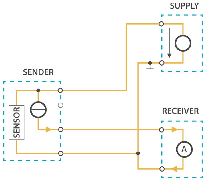 Figure 1: RAK5801 with 3-wire/4-20mA sensor
Four-Wire Sensor
Four-wire transmitters have four wires powered by the source voltage in them. The transmitter powers the current loop and the receptor acts as a floating load.
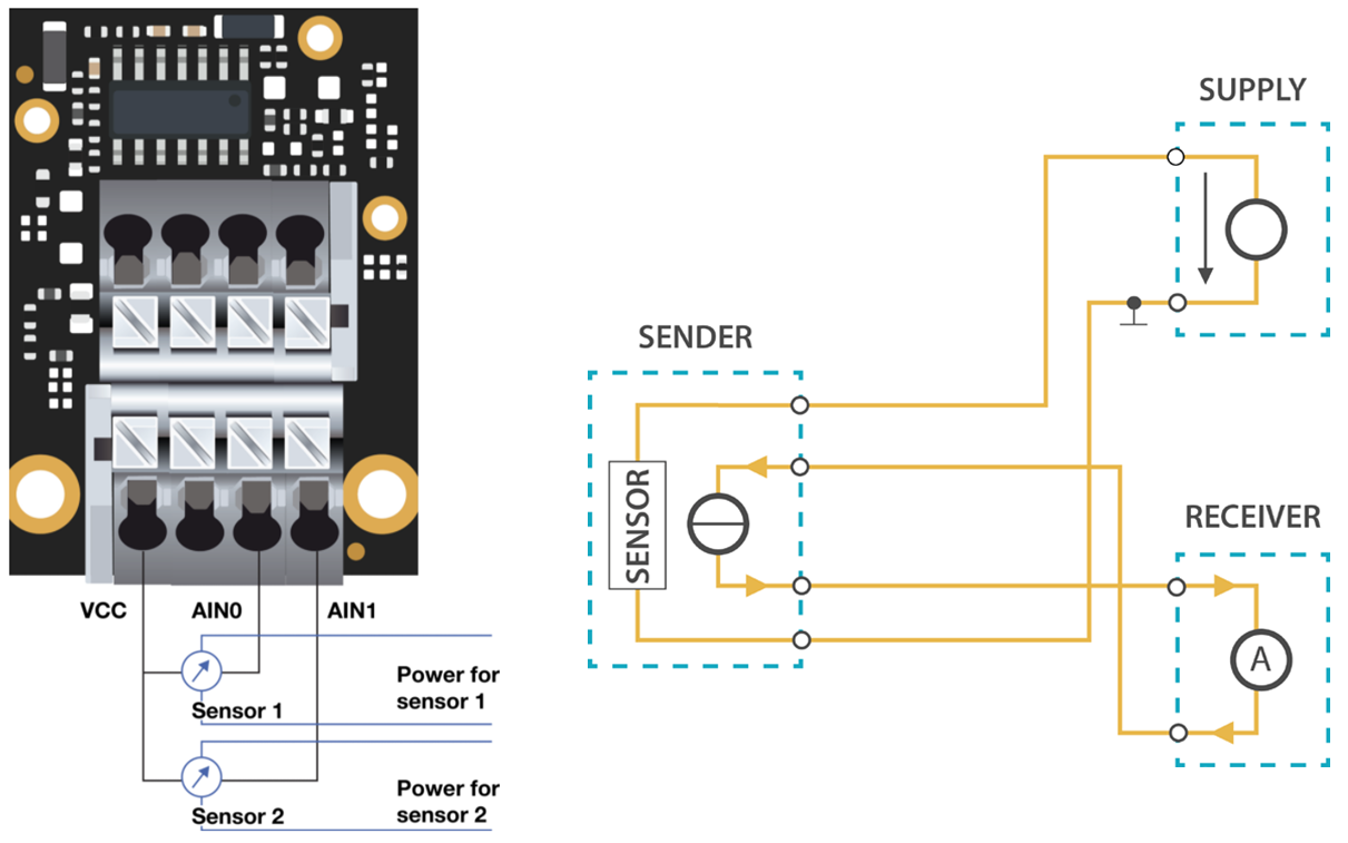 Figure 1: RAK5801 with 4-wire/4-20mA sensor
Now, you can connect the battery (optional) and USB cable to start programming your WisBlock Core.
- Batteries can cause harm if not handled properly.
- Only 3.7-4.2 V Rechargeable LiPo batteries are supported. It is highly recommended not to use other types of batteries with the system unless you know what you are doing.
- If a non-rechargeable battery is used, it has to be unplugged first before connecting the USB cable to the USB port of the board to configure the device. Not doing so might damage the battery or cause a fire.
- Only 5 V solar panels are supported. Do not use 12 V solar panels. It will destroy the charging unit and eventually other electronic parts.
- Make sure the battery wires are matching the polarity on the WisBlock Base board. Not all batteries have the same wiring.
Software Configuration and Example
The RAK5801 module includes a 12 V voltage source which is controlled by the WisBlock Core module via IO1 (WB_IO1) of the WisBlock Base. This GPIO must be set to HIGH before sampling. The 12 V voltage source is designed to provide power supply to 4-20 mA sensors. The majority of 4-20 mA sensor works in the 9-24 V range. Before connecting a sensor to the RAK5801 module, you must be sure that the sensor can safely operate at 12 V.
For RAK5801, the accessible ADC pin assignments are defined as follows in the Arduino IDE:
WB_IO4for AIN0, ADC Input pinWB_A1for AIN1, ADC Input pin
- WB_IO4 for AIN0 only works for the RAK4631 core module.
- If you will be using the RAK11200 core module, there are few hardware modifications needed to configure. Check the Pin Definition section in the Datasheet.
These are the quick links that go directly to the software guide for the specific WisBlock Core module you use:
- RAK5801 in RAK4631 WisBlock Core Guide
- RAK5801 in RAK11200 WisBlock Core Guide
- RAK5801 in RAK11310 WisBlock Core Guide
- LoRaWAN Hydraulic Pressure Monitoring with RAK5801
RAK5801 in RAK4631 WisBlock Core Guide
Sensor Connection on RAK5801
This is just an example and illustration on how to use the RAK5801 for external analog sensors. There are two analog input (ADC) pins available on the RAK5801, you can use any of the ADC pins as long as your sensors operate at 3.3 V or 12 V with 4-20 mA operating current.
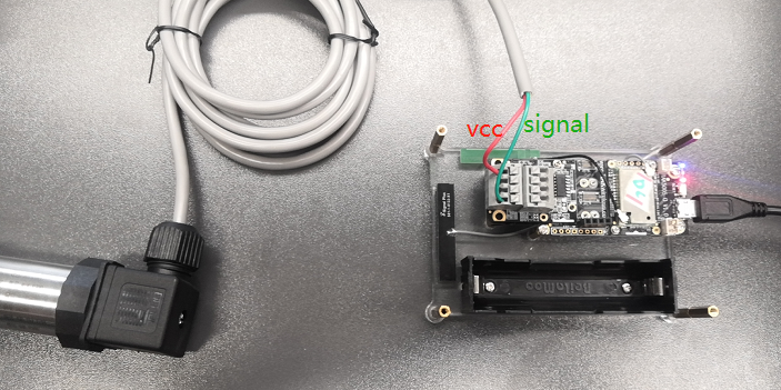 Figure 1: Connecting the RAK5801 to the SUP-P300 Hydraulic Pressure Sensor
If you already installed the RAKwireless Arduino BSP, the WisBlock Core and example code should now be available on the Arduino IDE.
- Select the RAK4631 WisBlock Core.
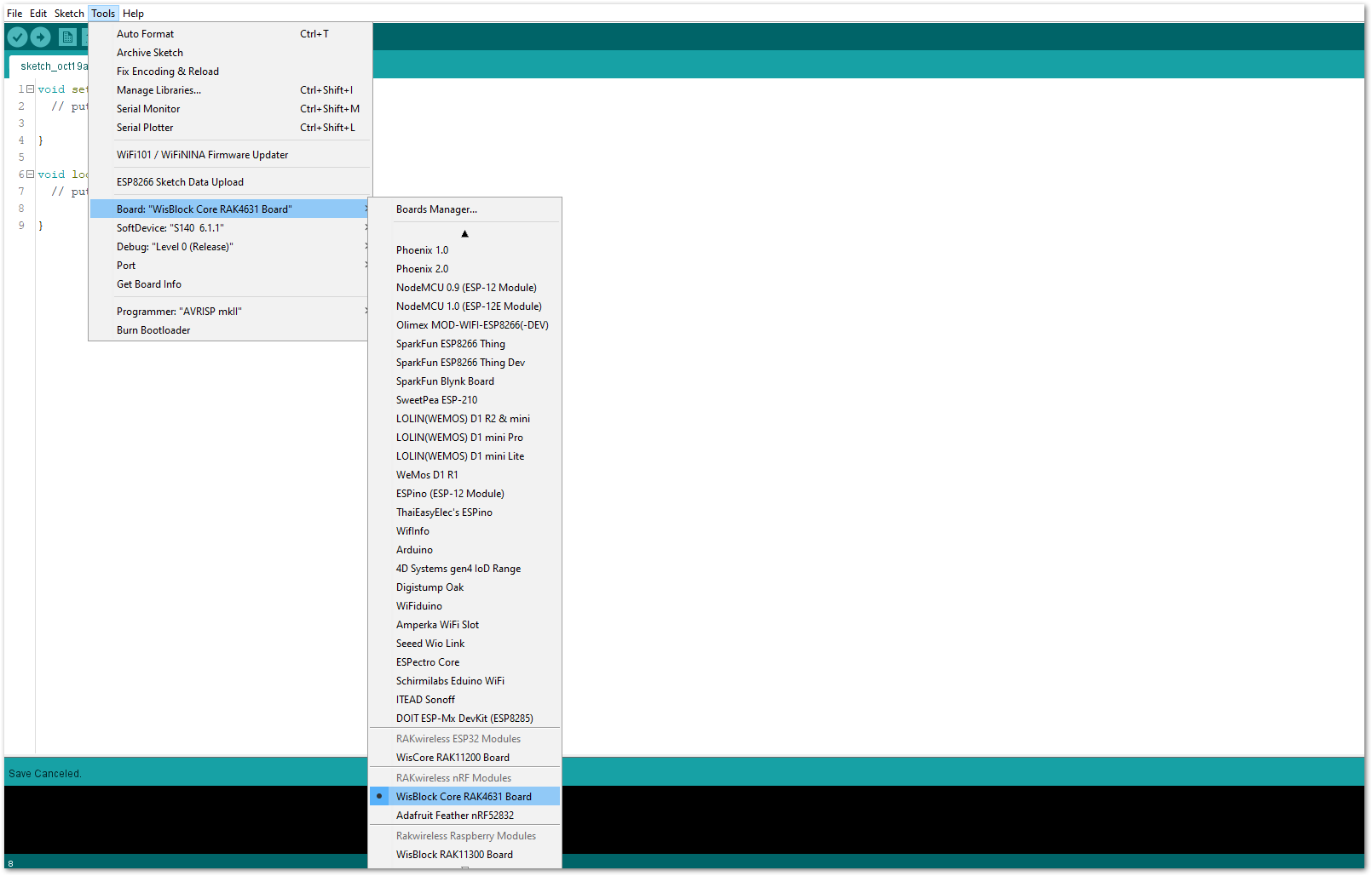 Figure 1: Selecting RAK4631 as WisBlock Core
- The Basic Sample Code for RAK5801 in GitHub will work on RAK4631 WisBlock Core. You can also open the example codes depending on your WisBlock Core, as shown in Figure 14.
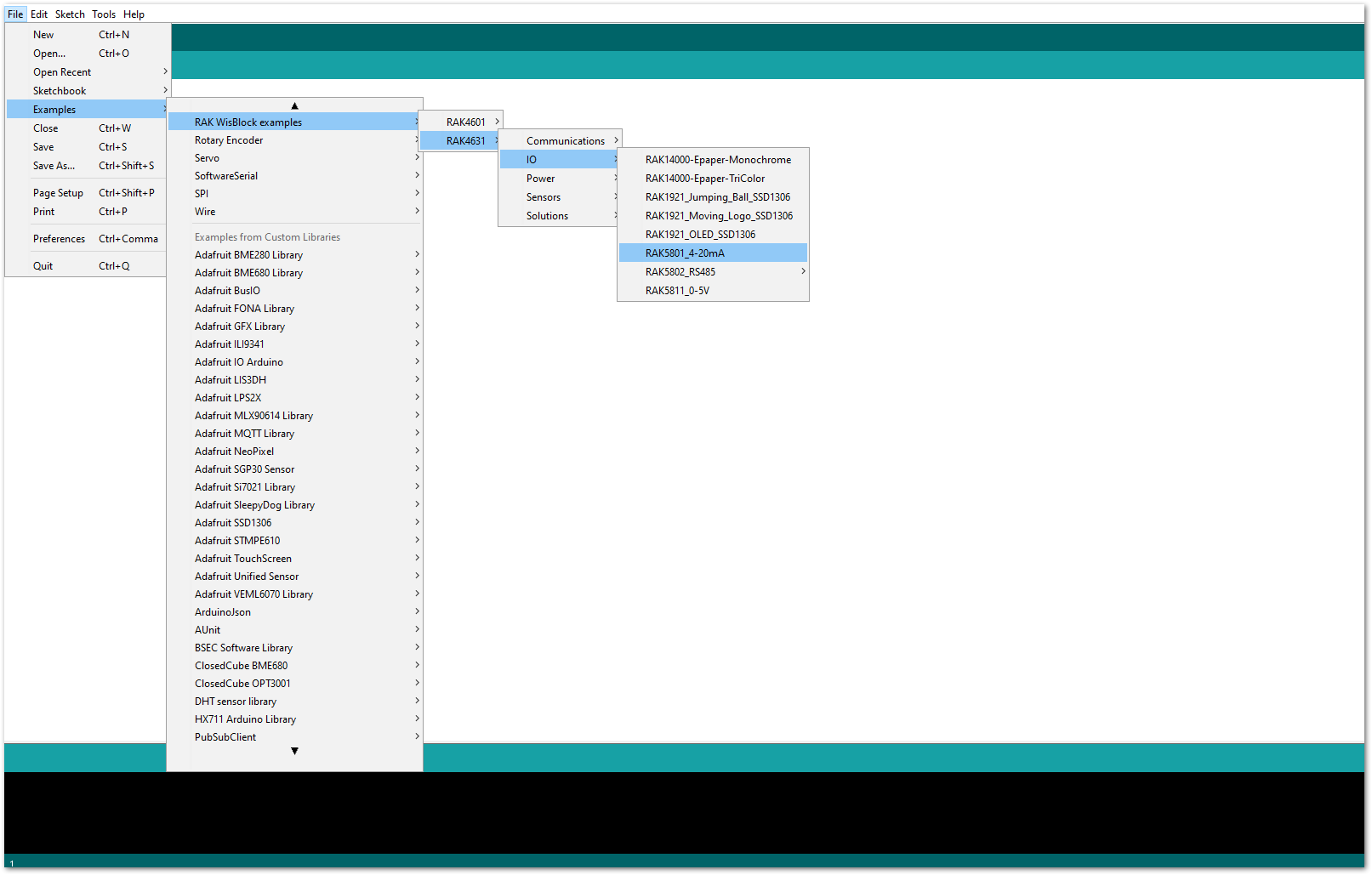 Figure 1: Opening RAK5801 example for RAK4631 WisBlock Core
Code Explanation
1.1 Initializes WisBlock IO 4-20mA Board
{
  /* WisBLOCK 5801 Power On*/

  pinMode(WB_IO1, OUTPUT);
  digitalWrite(WB_IO1, HIGH);

  /* WisBLOCK 5801 Power On*/
}
1.2 Get ADC Results
{
    for (i = 0; i < NO_OF_SAMPLES; i++)
  {
    mcu_ain_raw += analogRead(WB_A1);       // select the input pin A1 for the analog sensor
  }
  average_raw = mcu_ain_raw / i;
}
1.3 Calculate the Current Value
{
  voltage_ain = average_raw * 3.6 / 1024;     //raef 3.6v / 10bit ADC
  current_sensor = voltage_ain / 149.9 * 1000;  //WisBlock RAK5801 (0 ~ 20mA) I=U/149.9*1000 (mA)
}
- After opening the example code, you can now select the right port and upload the code.
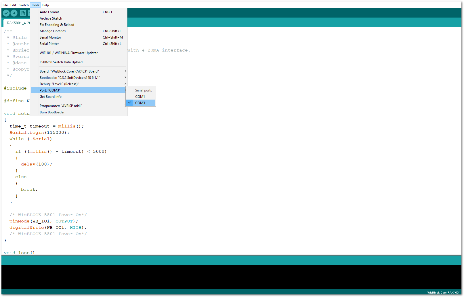 Figure 1: Selecting the correct Serial Port
- When you successfully uploaded the example sketch, open the Serial Monitor of the Arduino IDE to see the sensor's reading logs, as shown in Figure 16.
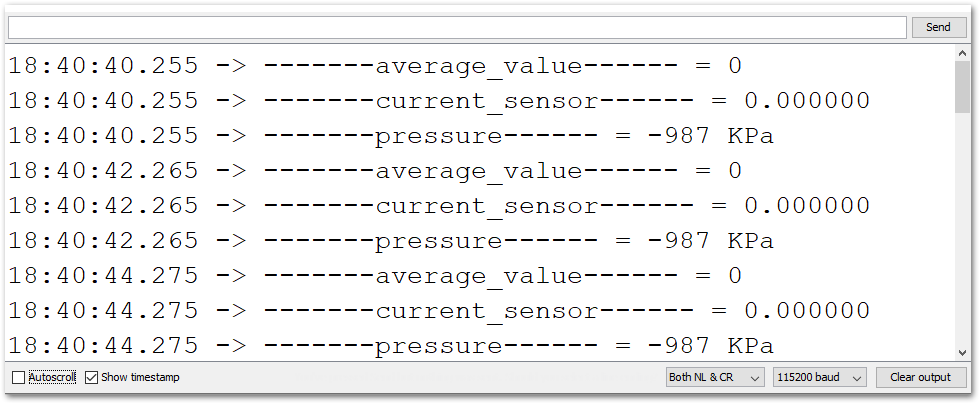 Figure 1: SUP-P300 Hydraulic Pressure sensor data logs
RAK5801 in RAK11200 WisBlock Core Guide
Sensor Connection on RAK5801
This is just an example and illustration on how to use the RAK5801 for external analog sensors. There are two analog input (ADC) pins available on the RAK5801. You can use any of the ADC pins as long as your sensors operate at 3.3 V or 12 V with 4-20 mA operating current.
 Figure 1: Connecting the RAK5801 to the SUP-P300 Hydraulic Pressure Sensor
If you already installed the RAKwireless Arduino BSP, the WisBlock Core and example code should now be available on the Arduino IDE.
- Select the RAK11200 WisBlock Core.
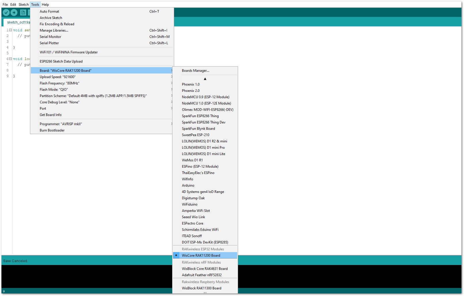 Figure 1: Selecting RAK11200 as WisBlock Core
- The Basic Sample Code for RAK5801 in GitHub will work on RAK11200 WisBlock Core. You can also open the example codes depending on your WisBlock Core, as shown in Figure 19.
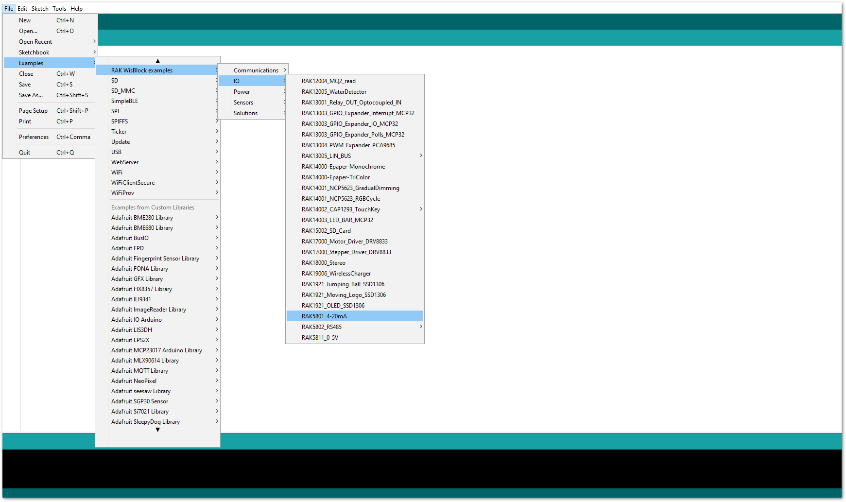 Figure 1: Opening RAK5801 example for RAK11200 WisBlock Core
Code Explanation
1.1 Initializes WisBlock IO 4-20mA Board
{
  /* WisBLOCK 5801 Power On*/

  pinMode(WB_IO1, OUTPUT);
  digitalWrite(WB_IO1, HIGH);

  /* WisBLOCK 5801 Power On*/
}
1.2 Get ADC Results
{
    for (i = 0; i < NO_OF_SAMPLES; i++)
  {
    mcu_ain_raw += analogRead(WB_A1);       // select the input pin A1 for the analog sensor
  }
  average_raw = mcu_ain_raw / i;
}
1.3 Calculate the Current Value
{
  voltage_ain = average_raw * 3.6 / 1024;     //raef 3.6v / 10bit ADC
  current_sensor = voltage_ain / 149.9 * 1000;  //WisBlock RAK5801 (0 ~ 20mA) I=U/149.9*1000 (mA)
}
- After opening the example code, you can now select the right port and upload the code.
RAK11200 requires the Boot0 pin to be configured properly first before uploading. If not done properly, uploading the source code to RAK11200 will fail. Check the full details on the RAK11200 Quick Start Guide.
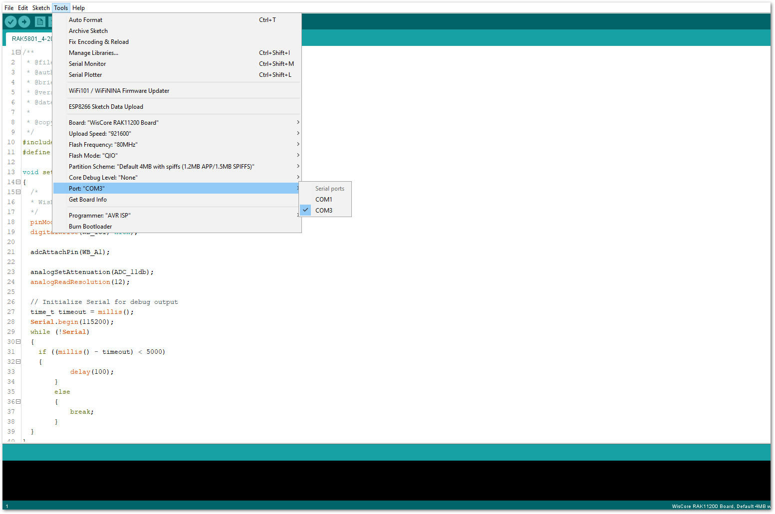 Figure 1: Selecting the correct Serial Port
- When you successfully uploaded the example sketch, open the Serial Monitor of the Arduino IDE to see the sensor's reading logs, as shown in Figure 21.
 Figure 1: SUP-P300 Hydraulic Pressure sensor data logs
RAK5801 in RAK11310 WisBlock Core Guide
Sensor Connection on RAK5801
This is just an example and illustration on how to use the RAK5801 for external analog sensors. There are two analog input (ADC) pins available on the RAK5801. You can use any of the ADC pins as long as your sensors operate at 3.3 V or 12 V with 4-20 mA operating current.
 Figure 1: Connecting the RAK5801 to the SUP-P300 Hydraulic Pressure Sensor
If you already installed the RAKwireless Arduino BSP, the WisBlock Core and example code should now be available on the Arduino IDE.
- Select the RAK11310 WisBlock Core.
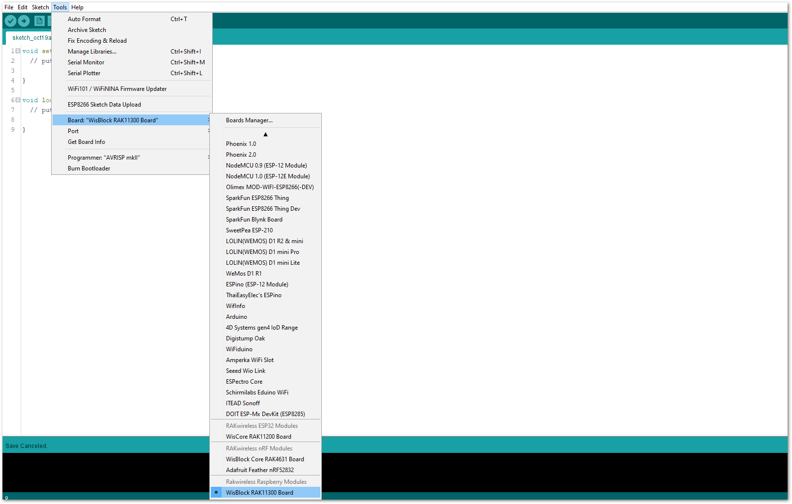 Figure 1: Selecting RAK11310 as WisBlock Core
- The Basic Sample Code for RAK5801 in GitHub will work on RAK11310 WisBlock Core. You can also open the example codes depending on your WisBlock Core, as shown in Figure 24.
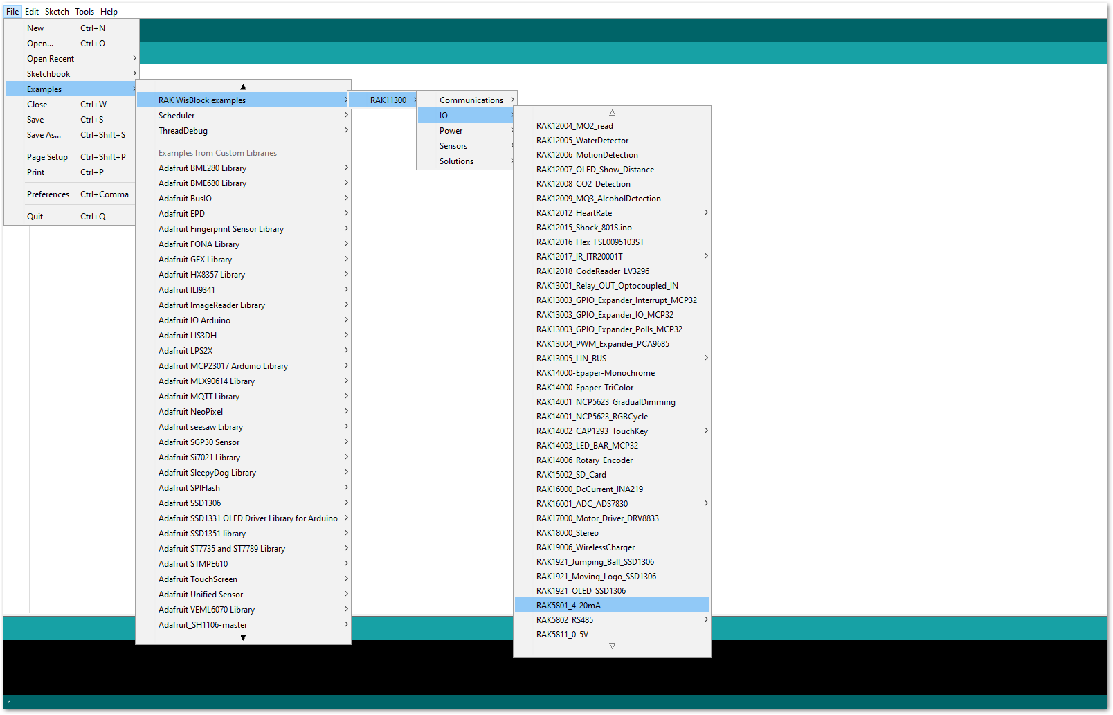 Figure 1: Opening RAK5801 example for RAK11310 WisBlock Core
Code Explanation
1.1 Initializes WisBlock IO 4-20mA Board
{
  /* WisBLOCK 5801 Power On*/

  pinMode(WB_IO1, OUTPUT);
  digitalWrite(WB_IO1, HIGH);

  /* WisBLOCK 5801 Power On*/
}
1.2 Get ADC Results
{
    for (i = 0; i < NO_OF_SAMPLES; i++)
  {
    mcu_ain_raw += analogRead(WB_A1);       // select the input pin A1 for the analog sensor
  }
  average_raw = mcu_ain_raw / i;
}
1.3 Calculate the Current Value
{
  voltage_ain = average_raw * 3.6 / 1024;     //raef 3.6v / 10bit ADC
  current_sensor = voltage_ain / 149.9 * 1000;  //WisBlock RAK5801 (0 ~ 20mA) I=U/149.9*1000 (mA)
}
- After opening the example code, you can now select the right port and upload the code.
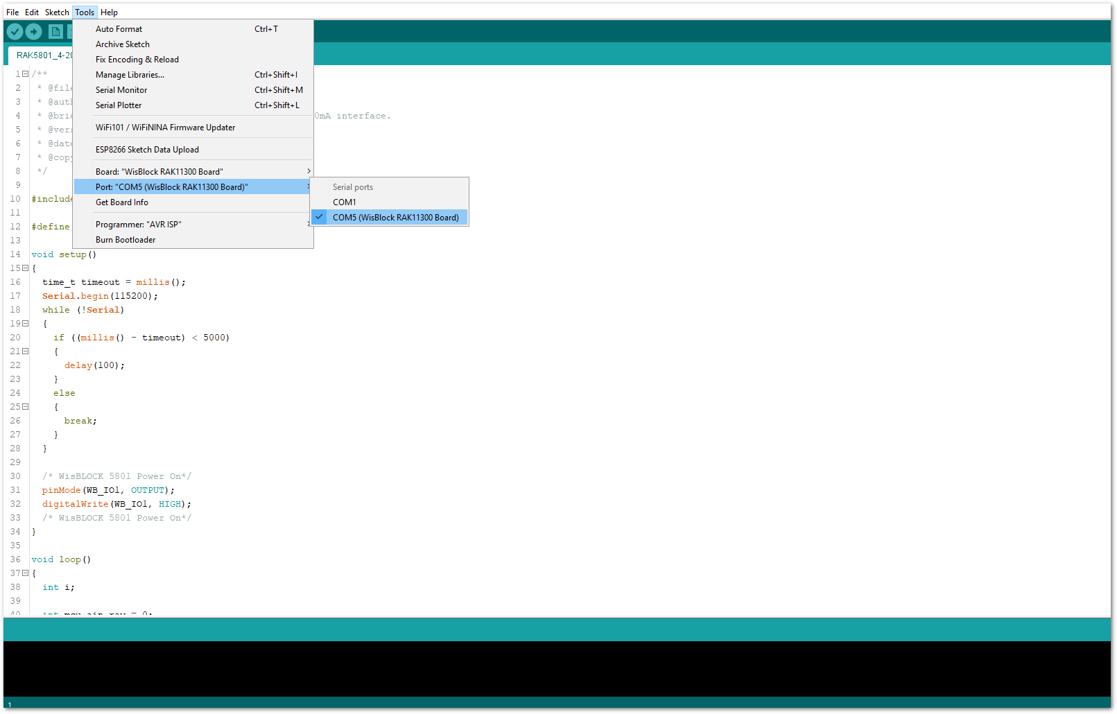 Figure 1: Selecting the correct Serial Port
- When you successfully uploaded the example sketch, open the Serial Monitor of the Arduino IDE to see the sensor's reading logs, as shown in Figure 26.
 Figure 1: SUP-P300 Hydraulic Pressure sensor data logs
LoRaWAN Hydraulic Pressure Monitoring with RAK5801
For WisBlock Core RAK4630, check the example for LoRaWAN Hydraulic Pressure Monitoring with RAK5801 Module.
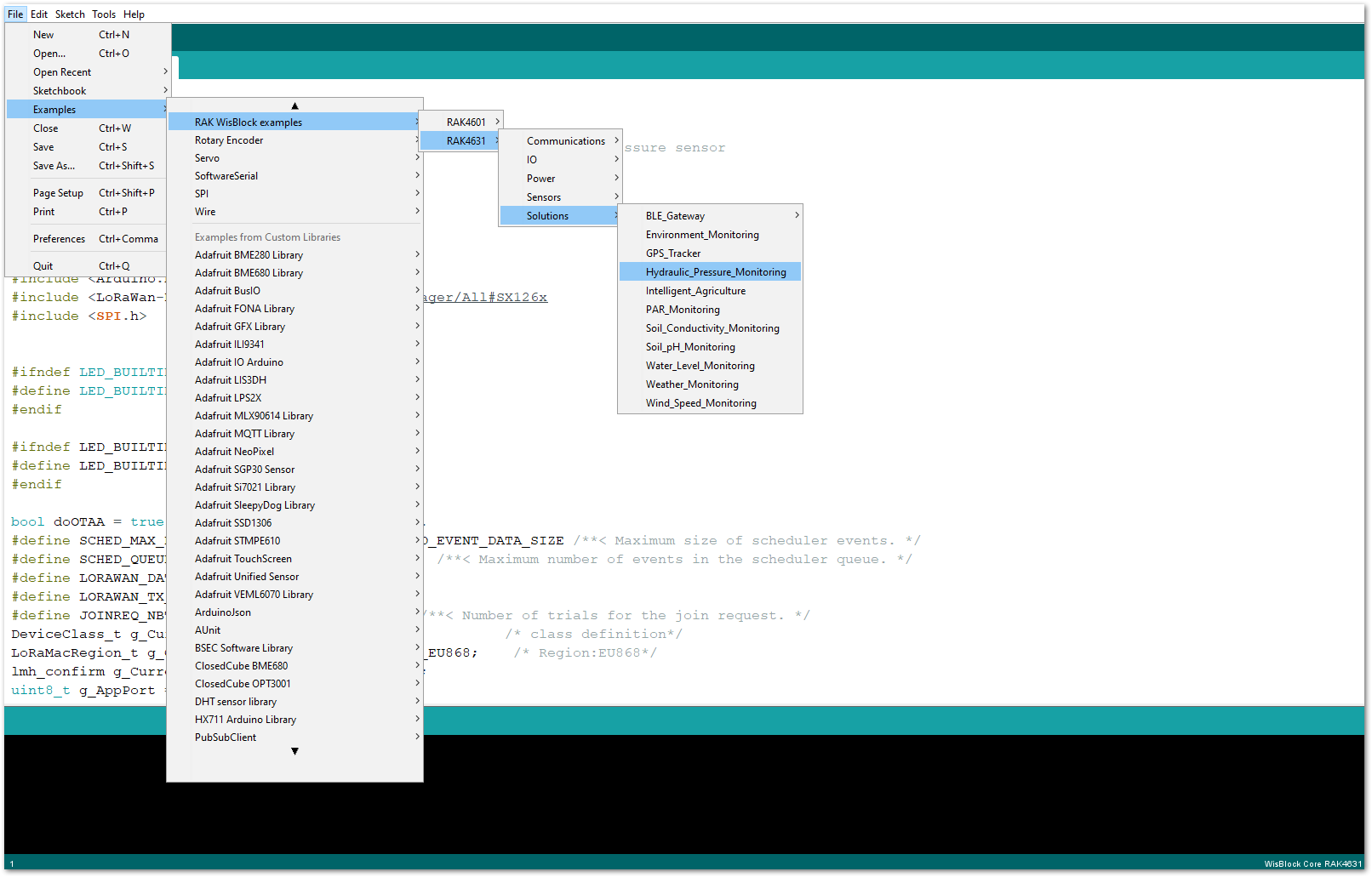 Figure 1: LoRaWAN Hydraulic Pressure Monitoring example code