RAK5802 WisBlock RS485 Interface Module Quick Start Guide
Prerequisite
What Do You Need?
Before going through each and every step on using the RAK5802 WisBlock module, make sure to prepare the necessary items listed below:
Hardware
- 2 x RAK5802
- 2 x Your choice of WisBlock Base
- 2 x Your choice of WisBlock Core
- 2 x USB Cable
- Li-Ion/LiPo battery (optional)
- Solar charger (optional)
Software
- Download and install Arduino IDE.
- To add the RAKwireless Core boards on your Arduino board, install the RAKwireless Arduino BSP. Follow the steps in the GitHub repo.
Product Configuration
Hardware Setup
WisBlock can integrate this module, which extends the WisBlock system with an industrial RS485 data transmission interface.
RAK5802 supports one RS485 interface. There are also two voltage sources available on the connectors, which you can use on your external device or circuit. One is the battery voltage via PWR pin, which is directly coming from the battery connected to the WisBlock Base. The other one is the 3.3 V regulated output, which comes from the WisBlock Base, as well, and powers the entire WisBlock board, including the WisBlock Core and other connected modules. In addition, an Analog A1 input (via WB_A1 in code) and I2C interface connection are available on the crimping terminal.
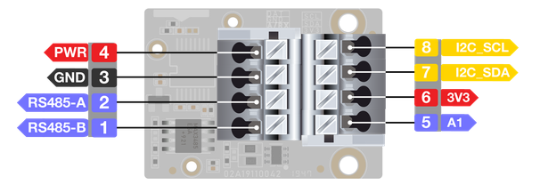 Figure 1: RAK5802 sensor connector
For more information about the RAK5802, refer to the Datasheet.
The RAK5802 module is part of the WisBlock Interface category, which connects to the base board through the IO slot. Also, always secure the connection of the WisBlock module by using compatible screws.
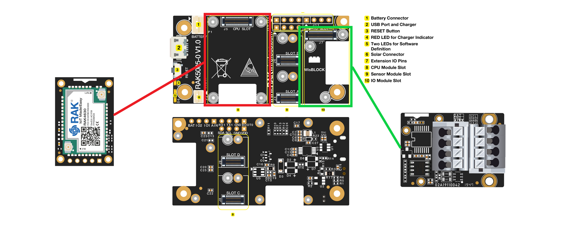 Figure 1: RAK5802 connection to WisBlock Base
Installation
Mounting Mechanism
The RAK5802 module is part of the WisBlock Interface category, which connects to the baseboard through the IO slot. The installation method is shown in Figure 3 and Figure 4.
- Keep the RAK5802 module parallel to the baseboard, and gently place and plug WisConnector into the IO slot receptacle of the baseboard. The IO slot has an outer silkscreen on it to assist with the alignment. At this point, apply force evenly along with the module and press again. There will be a sound to confirm the successful completion of the attachment process.
For detailed instructions, refer to the WisBlock Installation Guide.
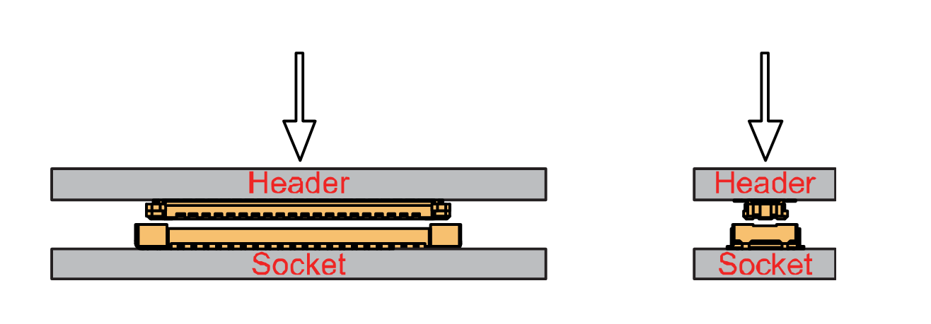 Figure 1: WisConnector
- Always secure the RAK5802 module with 3 x M1.2 x3 pan head screws, as shown in Figure 4.
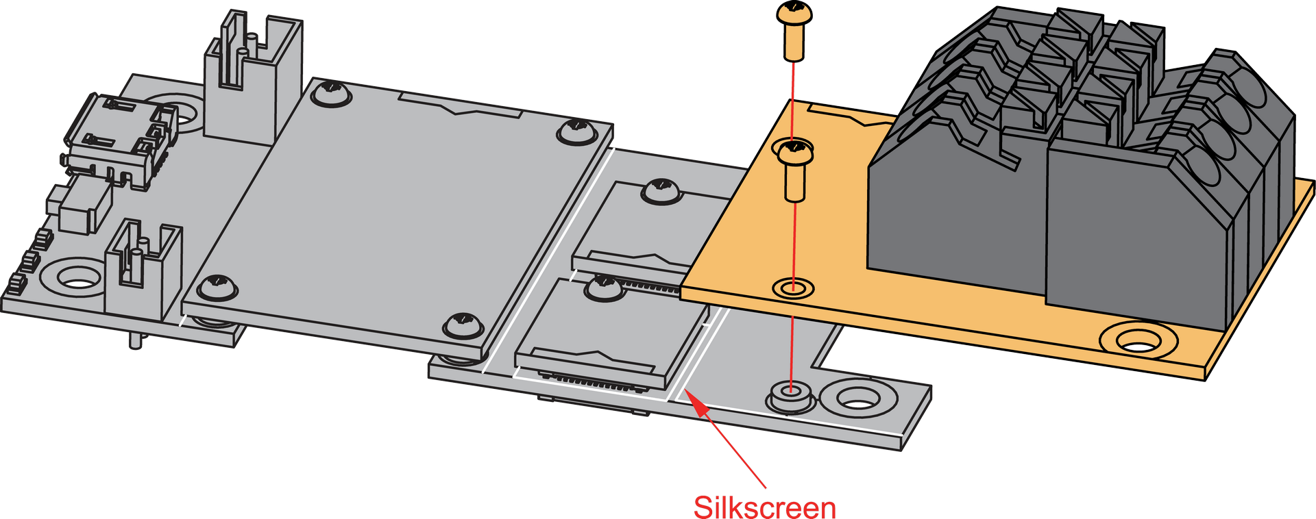 Figure 1: RAK5802 connection to WisBlock Base
RAK5802 Sensor Connector Crimping Mechanism
The RAK5802 features a fast-crimping terminal connector to simplify and ensure the wiring process on the fields. The fast-crimping terminal can support cable with a width between 20 AWG to 24 AWG. The usual stripping length is around 6 to 7 mm.
As shown in Figure 5, during the crimping process, you should first press down and maintain the spring head of the crimping terminal firmly, then insert the stripped cable head into the corresponding connector’s hole. Once inserted correctly, then release the spring head, and the crimping process is completed.
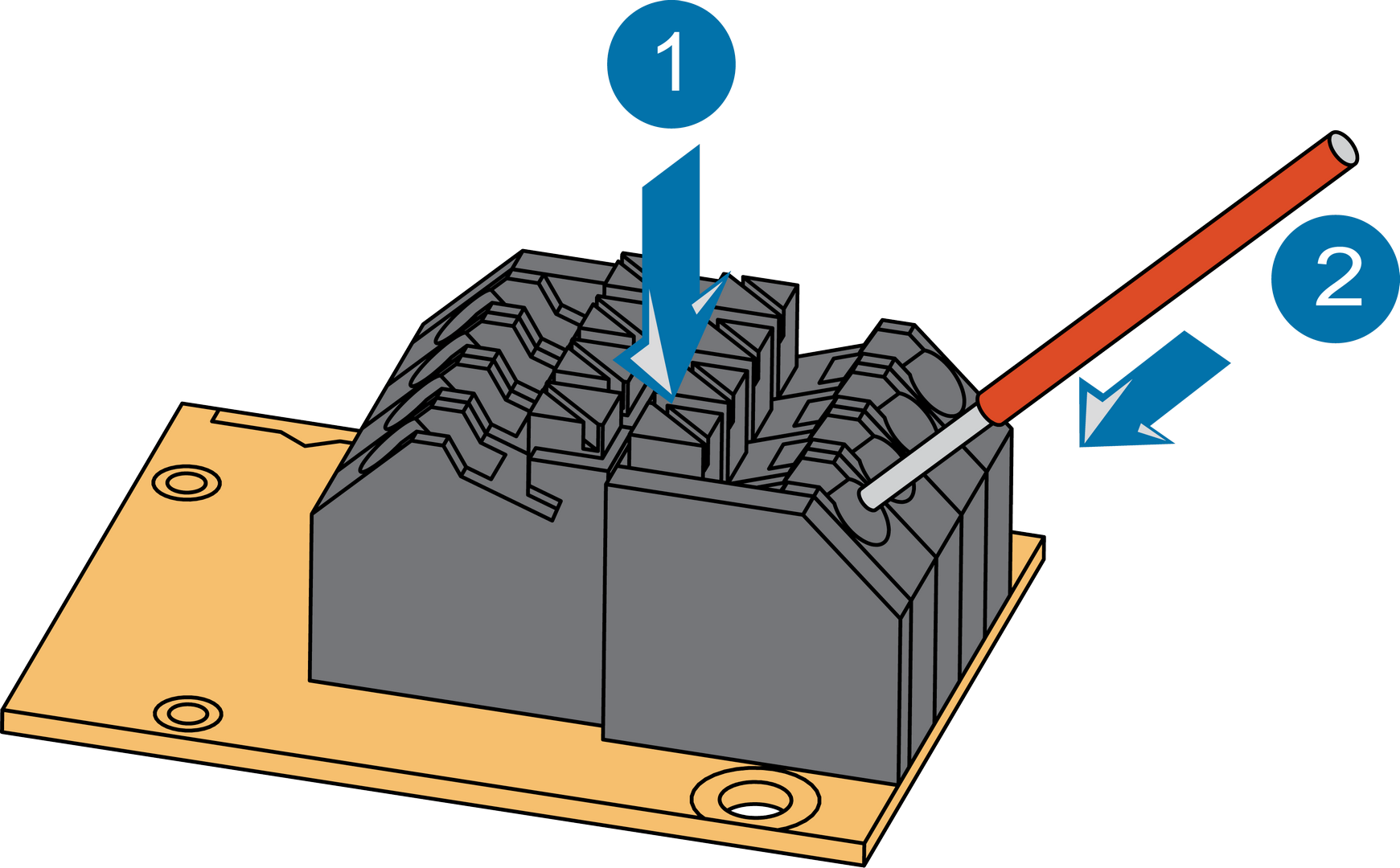 Figure 1: RAK5802 Sensor Connector
Disassembling Procedure
The procedure in disassembling any type of WisBlock module is the same.
- Remove the screws.
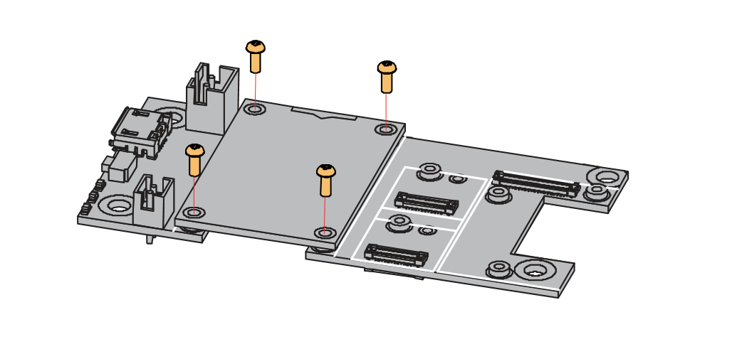 Figure 1: Removing screws from the WisBlock module
- Once the screws are removed, check the silkscreen of the module to find the correct location where force can be applied.
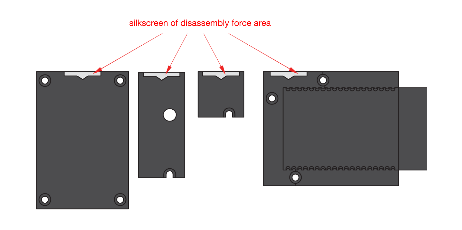 Figure 1: Detaching silkscreen on the WisBlock module
- Apply force to the module at the position of the connector, as shown in Figure 8, to detach the module from the baseboard.
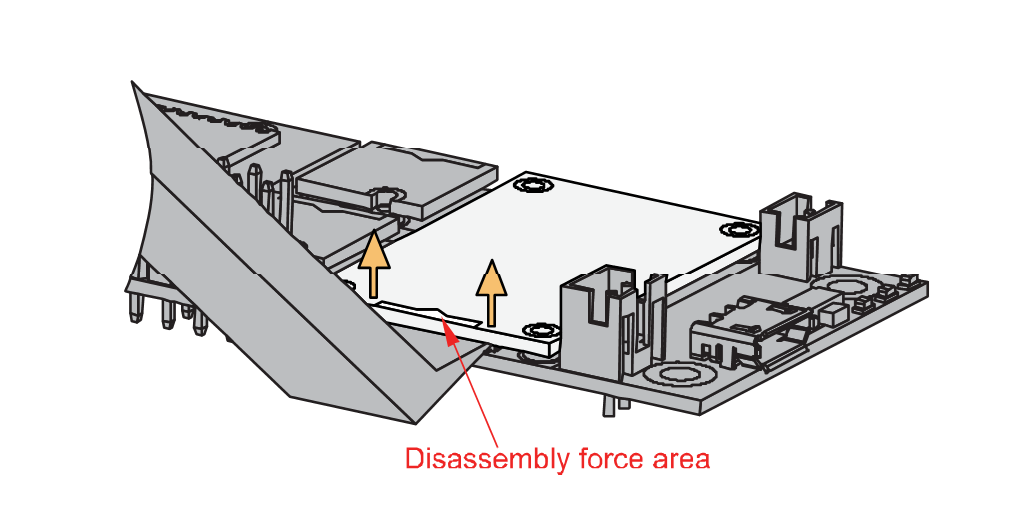 Figure 1: Applying even forces on the proper location of a WisBlock module
If you will connect other modules to the remaining WisBlock Base slots, check on the WisBlock Pin Mapper tool for possible conflicts. RAK5802 uses UART and I2C communication lines, and it can cause possible conflict especially on other WisBlock Modules connected to Slot A to D of the WisBlock Base.
After all this setup, you can now connect the battery (optional) and USB cable to start programming your WisBlock Core.
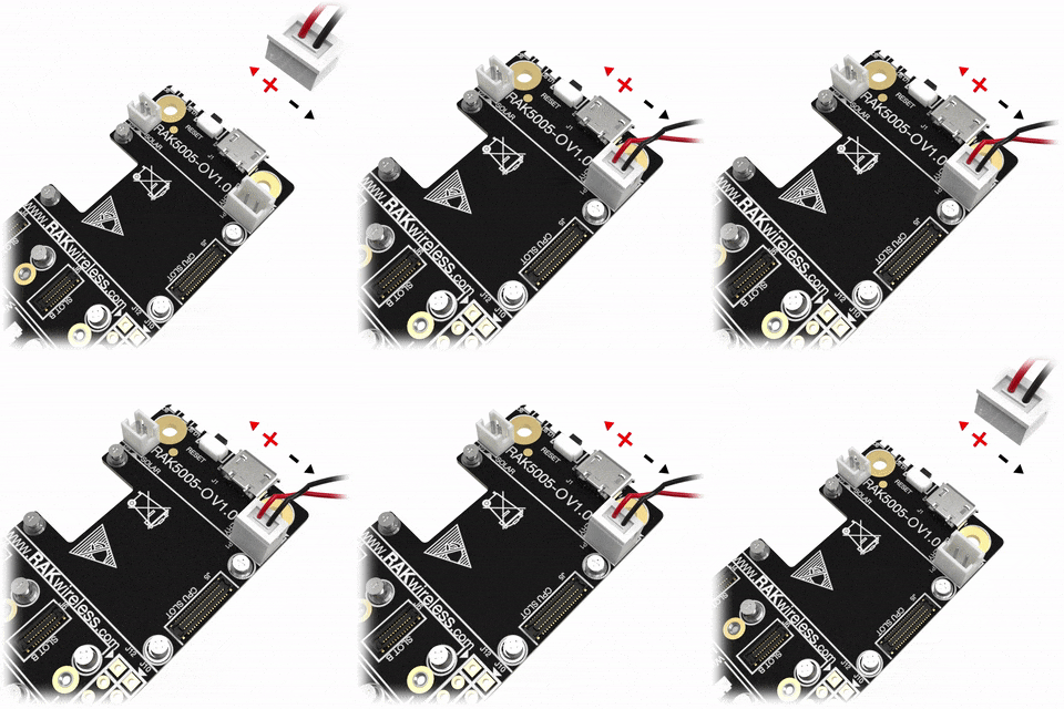 Figure 1: Battery connection to WisBlock Base Board
- Batteries can cause harm if not handled properly.
- Only 3.7-4.2 V Rechargeable LiPo batteries are supported. It is highly recommended not to use other types of batteries with the system unless you know what you are doing.
- If a non-rechargeable battery is used, it has to be unplugged first before connecting the USB cable to the USB port of the board to configure the device. Not doing so might damage the battery or cause a fire.
- Only 5 V solar panels are supported. Do not use 12 V solar panels. It will destroy the charging unit and eventually other electronic parts.
- Make sure the battery wires are matching the polarity on the WisBlock Base board. Not all batteries have the same wiring.
Software Configuration and Example
A ready-to-use SW library and tutorial make it easy to connect any sensor that is using the RS485 interface.
The sample code will require two sets of WisBlock Base (RAK5005-O), WisBlock Core (RAK4631/RAK11200) and WisBlock RS485 Interface Module. You only need to connect the two wires of the RS485 bus, as shown in Figure 10.
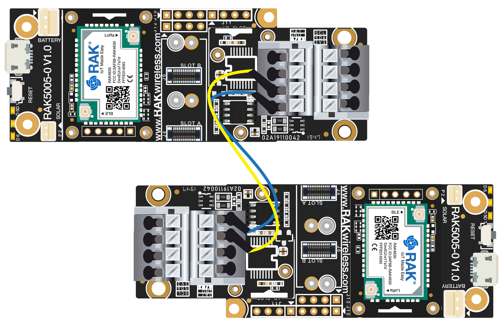 Figure 1: Connection Diagram
Initial Test of the RAK5802 WisBlock Module
If you already installed the RAKwireless Arduino BSP, the WisBlock Core and example code should now be available on the Arduino IDE.
- You need to select first the WisBlock Core you have, as shown in Figure 11 to Figure 13.
Using RAK4631 WisBlock Core
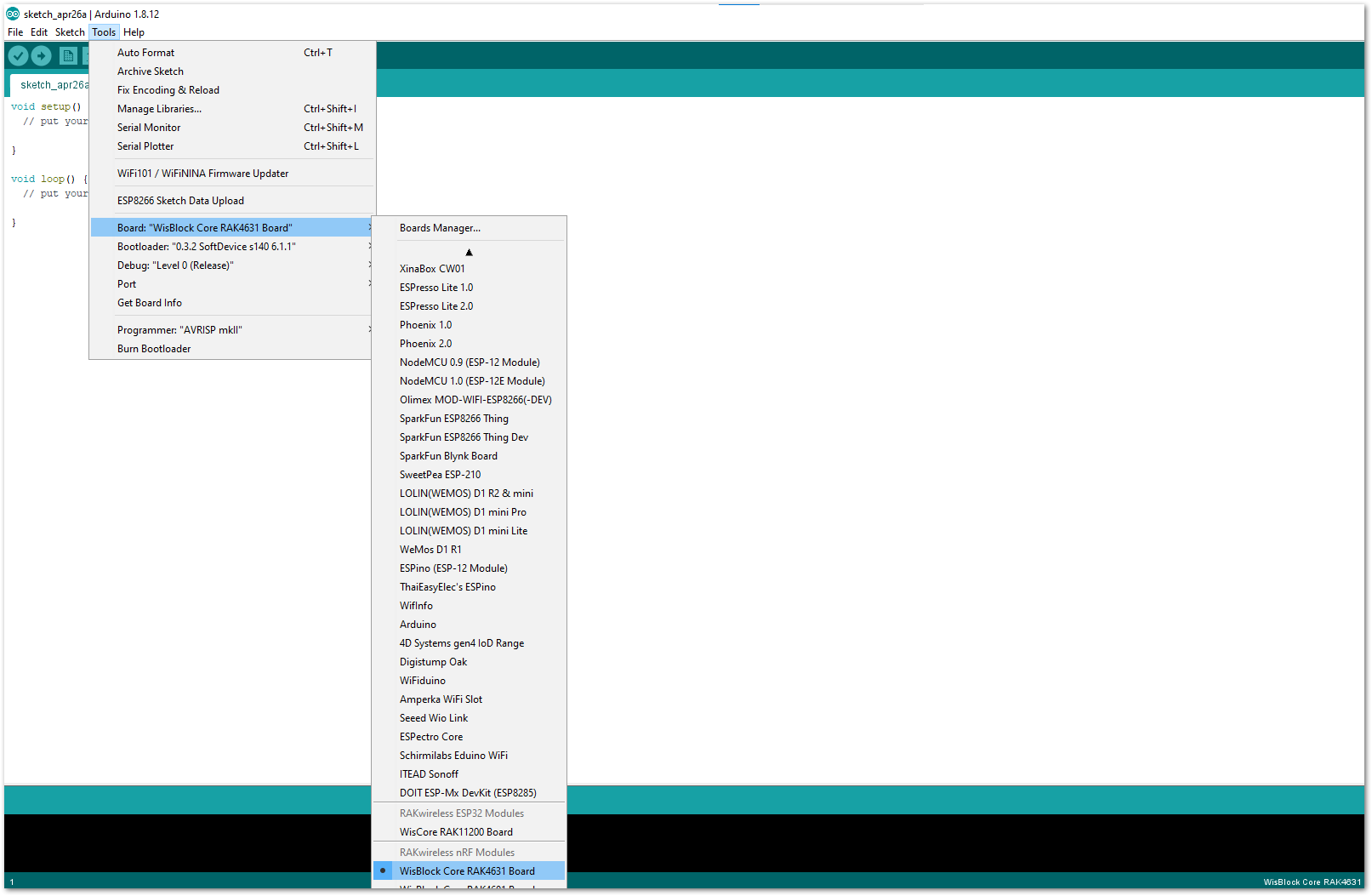 Figure 1: Selecting RAK4631 as WisBlock Core
Using RAK11200 WisBlock Core
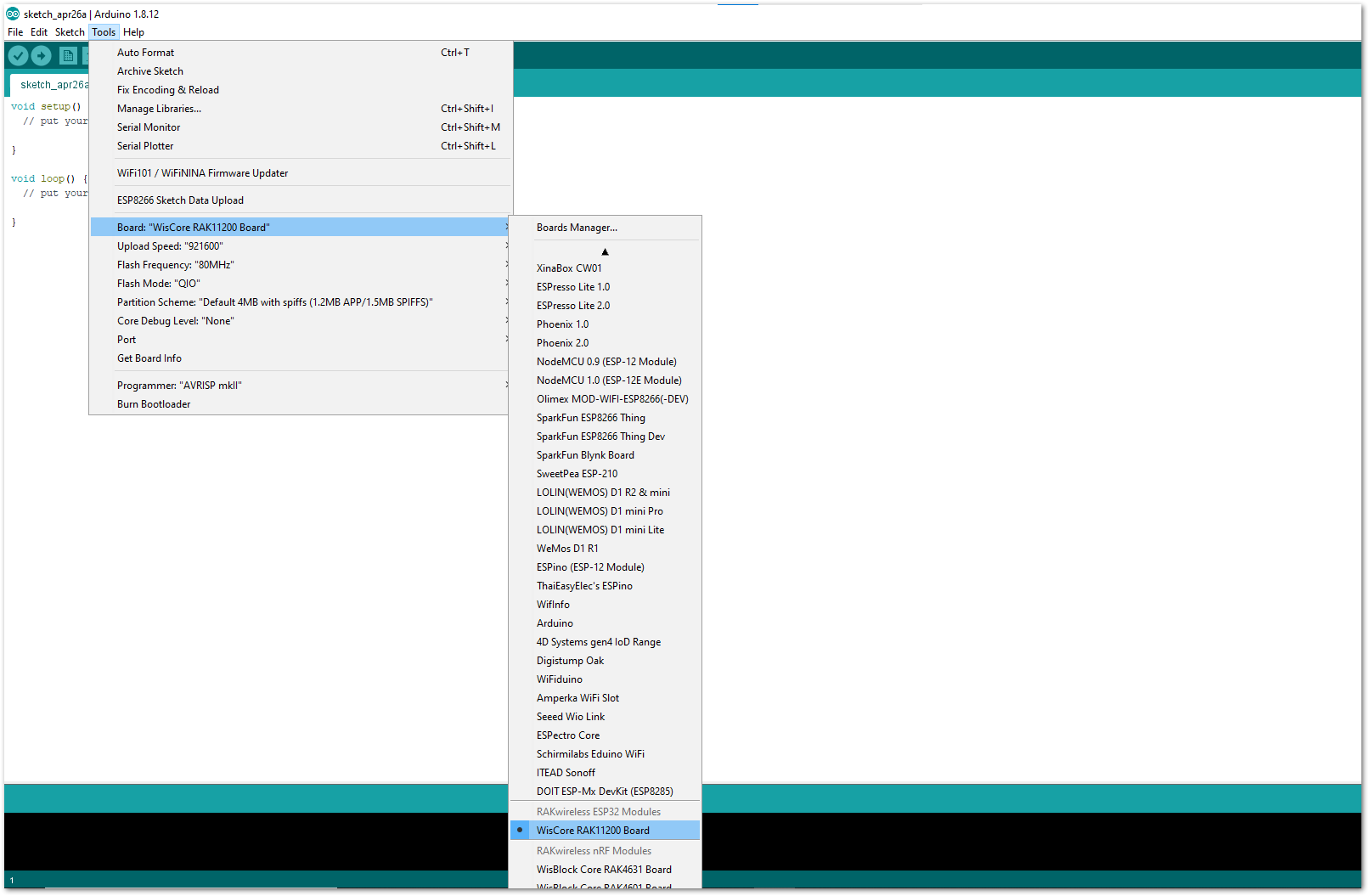 Figure 1: Selecting RAK11200 as WisBlock Core
Using RAK11300 WisBlock Core
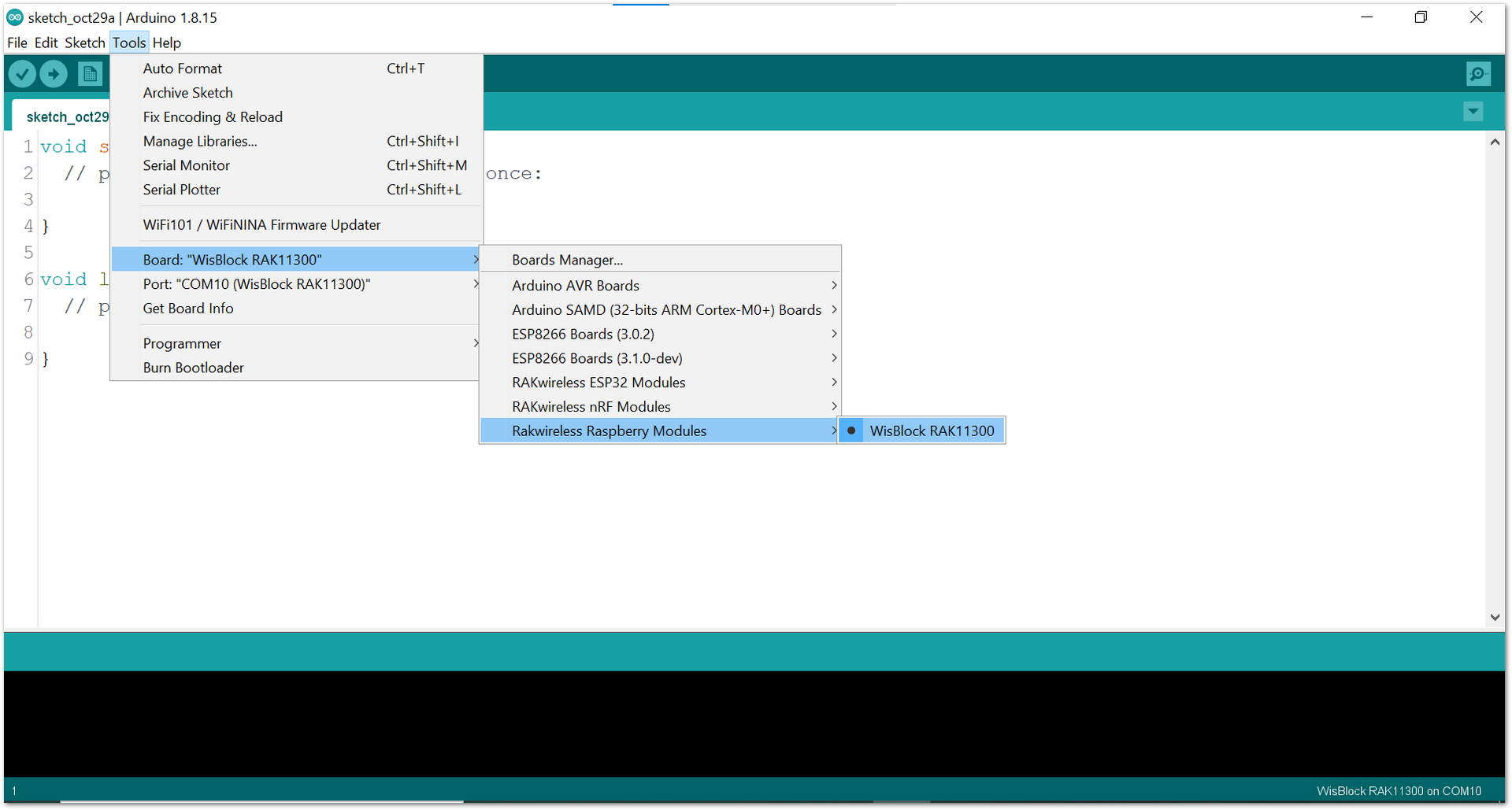 Figure 1: Selecting RAK11300 as WisBlock Core
- The Basic Sample Code for RAK5802 in GitHub will work on all WisBlock Core. You can open the example codes depending on your WisBlock Core, as shown in Figure 14 to Figure 16.
- Sample code for RAK4631
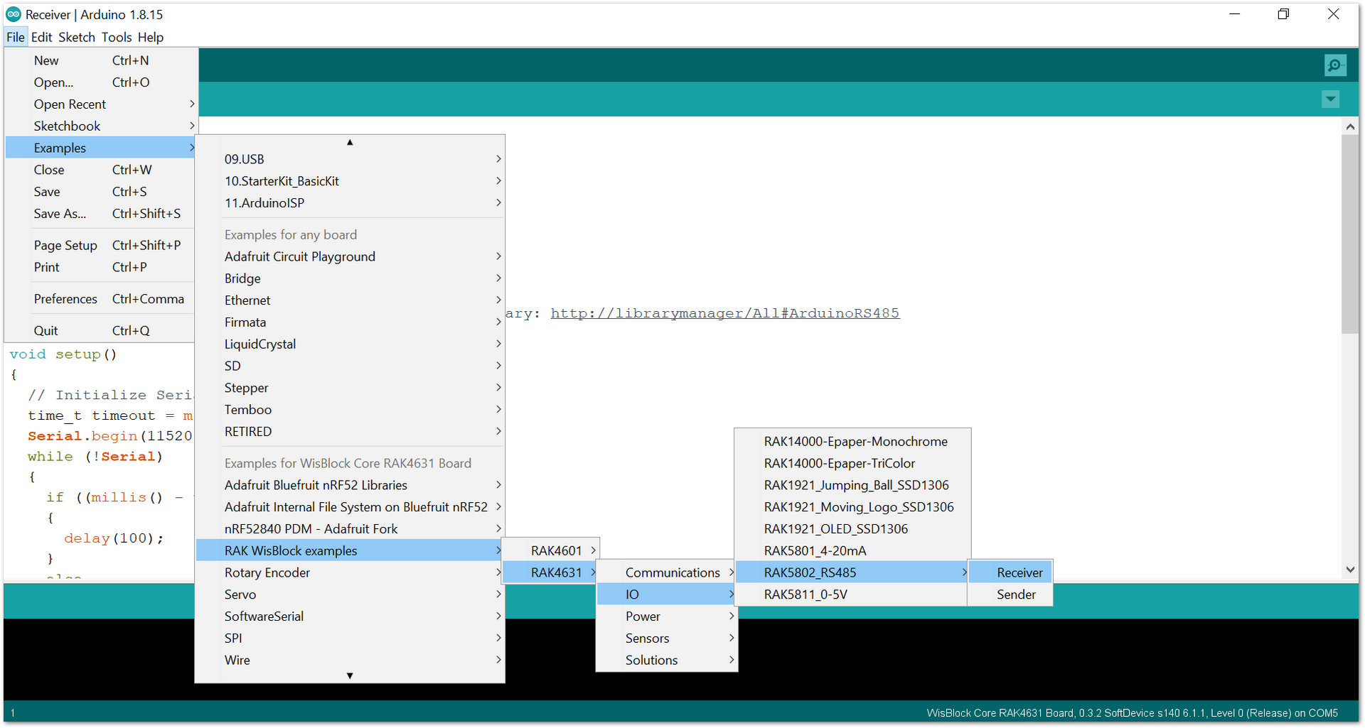 Figure 1: Opening RAK5802 example code for RAK4631 WisBlock Core
- Sample code for RAK11200
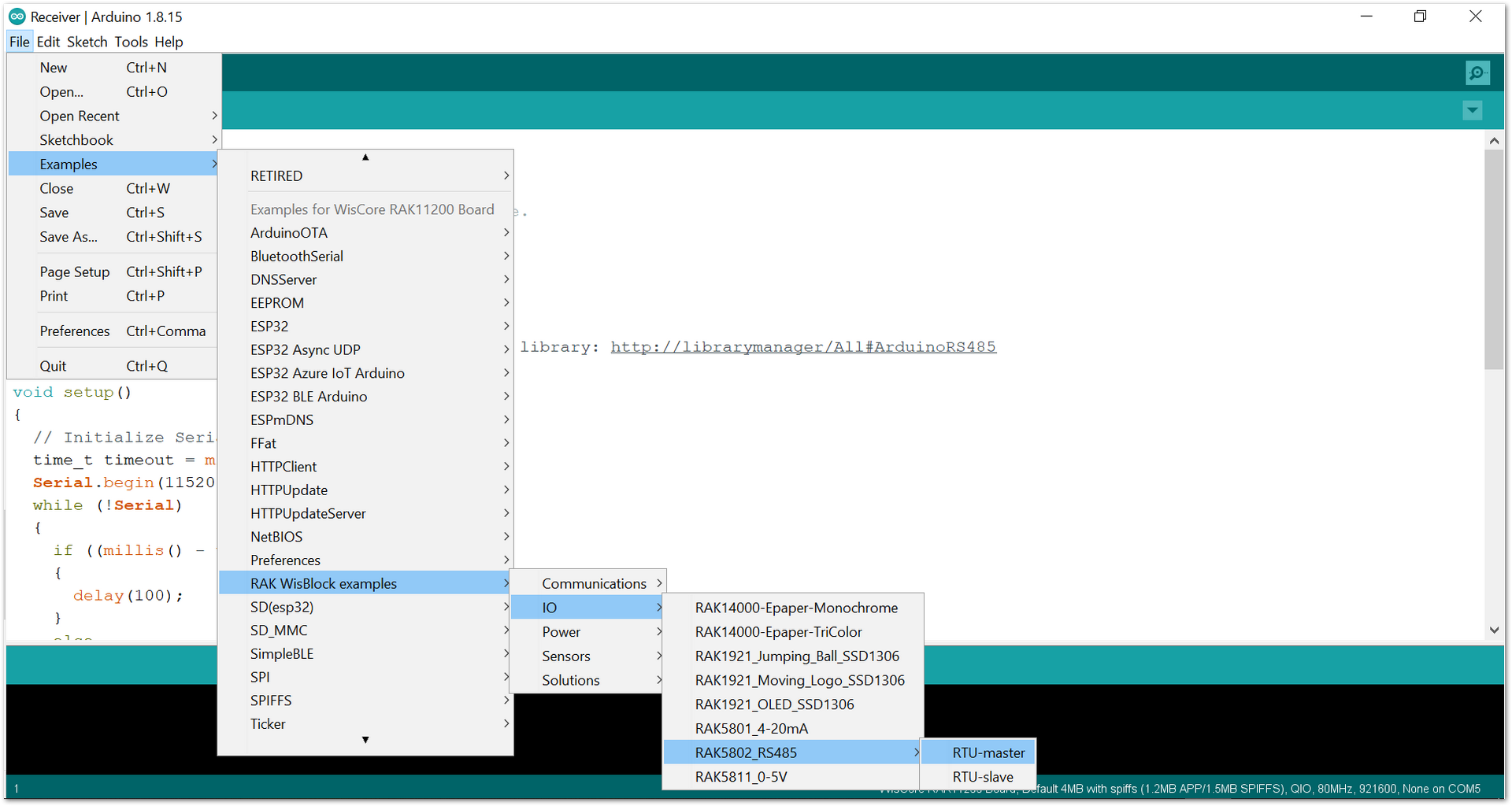 Figure 1: Opening RAK5802 example code for RAK11200 WisBlock Core
- Sample code for RAK11300
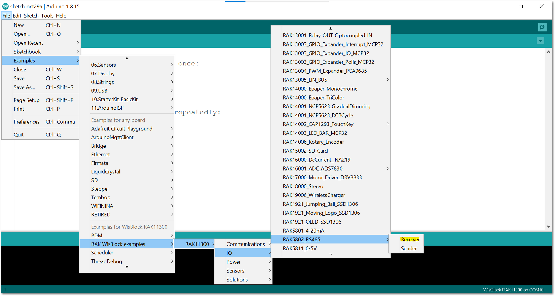 Figure 1: Opening RAK5802 example code for RAK11300 WisBlock Core
- Once the example code is open, install the Arduino RS485 library by clicking the yellow-highlighted link, as shown in Figure 17 and Figure 18. Or, if you are using Modbus protocol, install the Arduino Modbus.
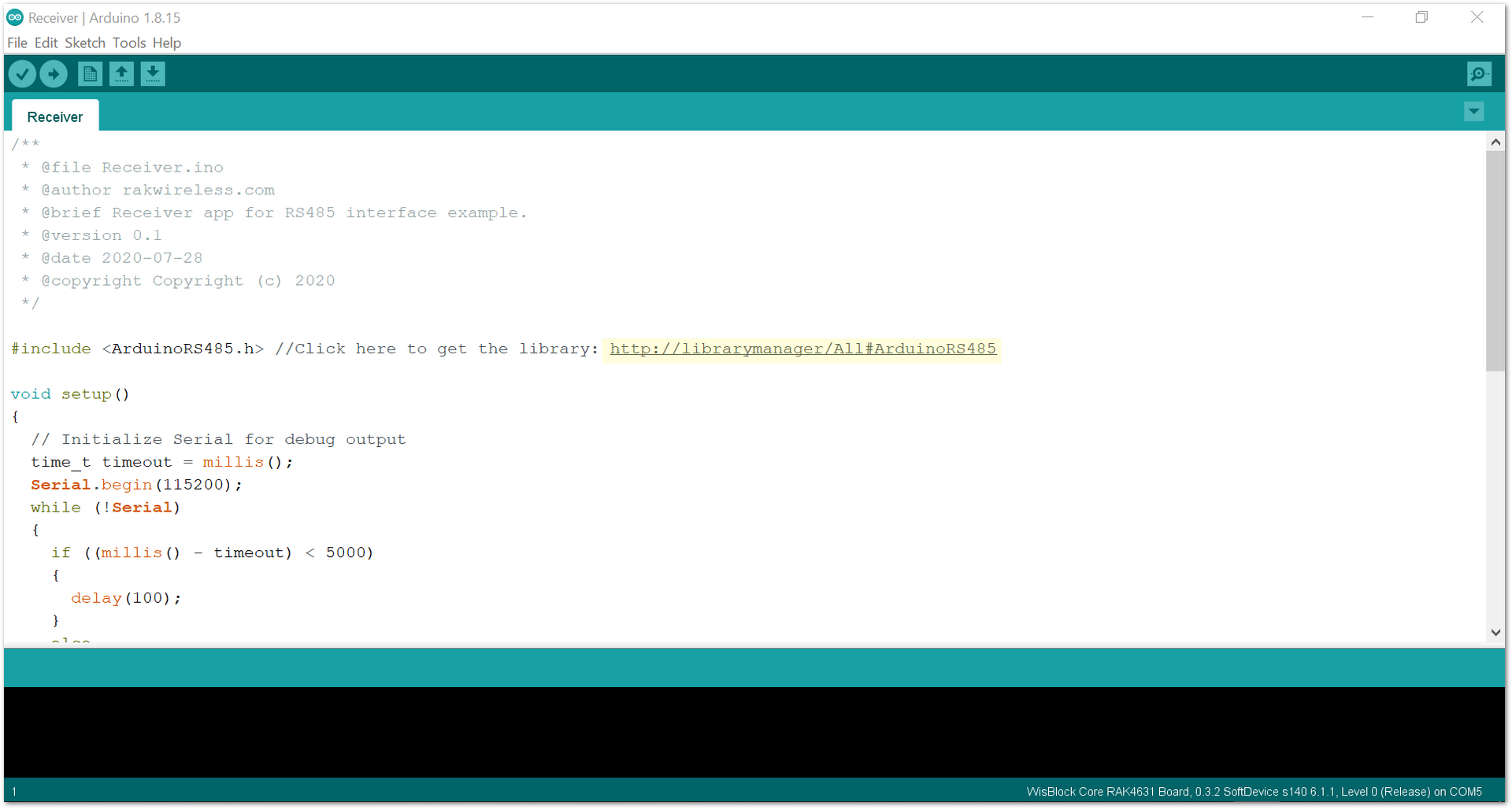 Figure 1: Installing the compatible library for RAK5802 Module
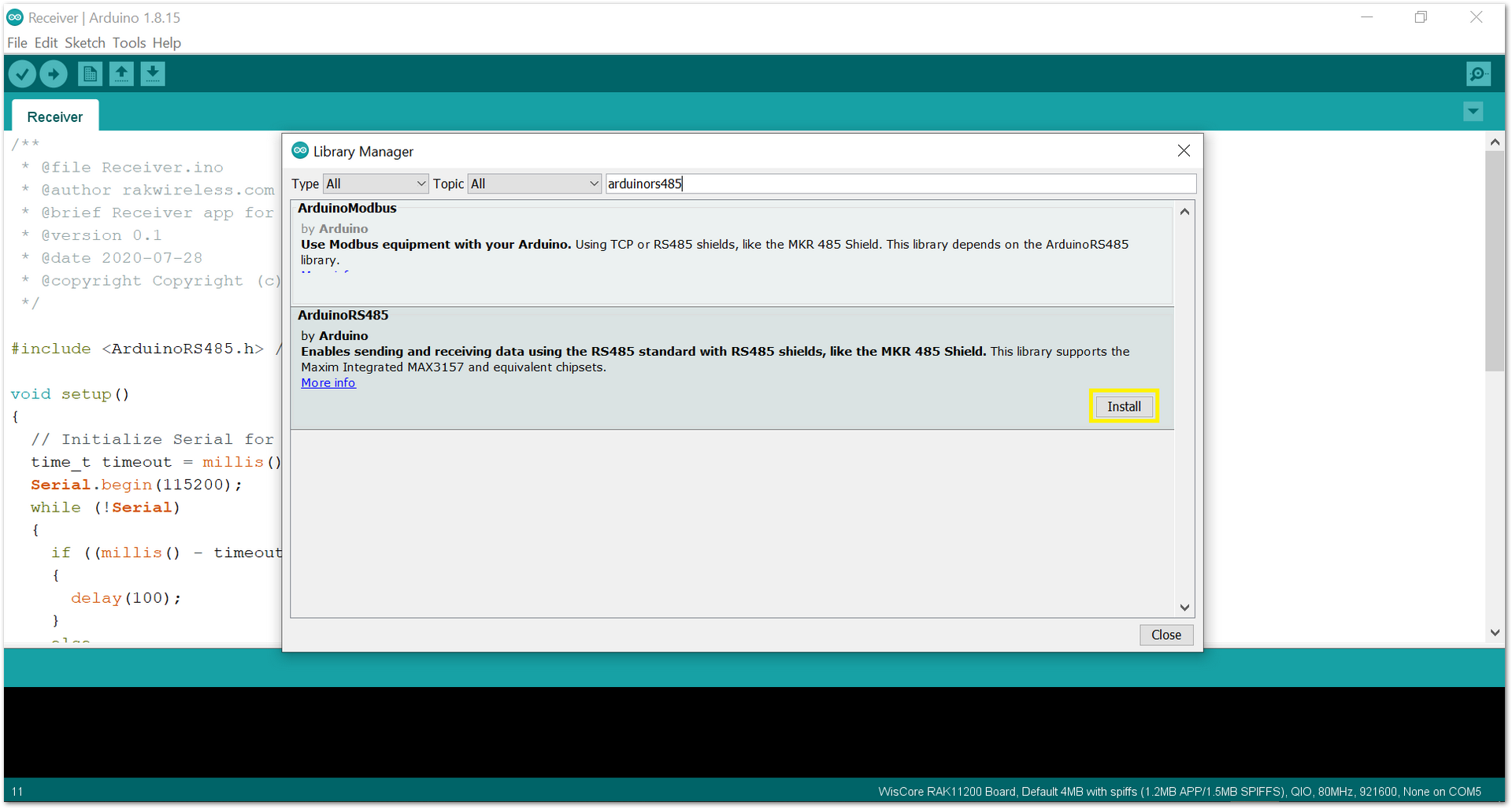 Figure 1: Accessing the library used for RAK5802 Module
- After successful installation of the library, you can now select the right serial port and upload the 'Receiver' code to the first board and 'Sender' code to the second board, as shown in Figure 19 and Figure 20.
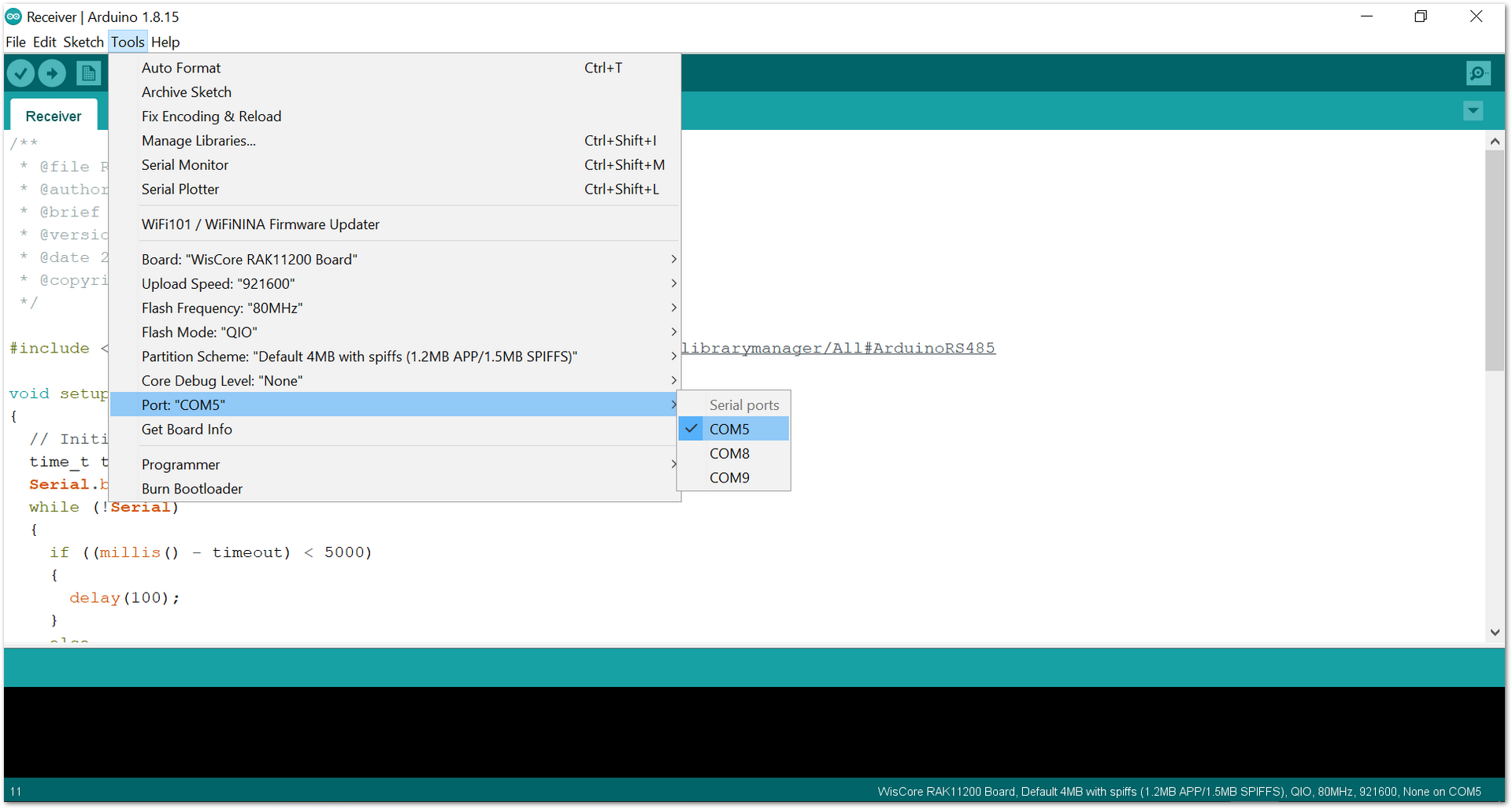 Figure 1: Selecting the correct Serial Port
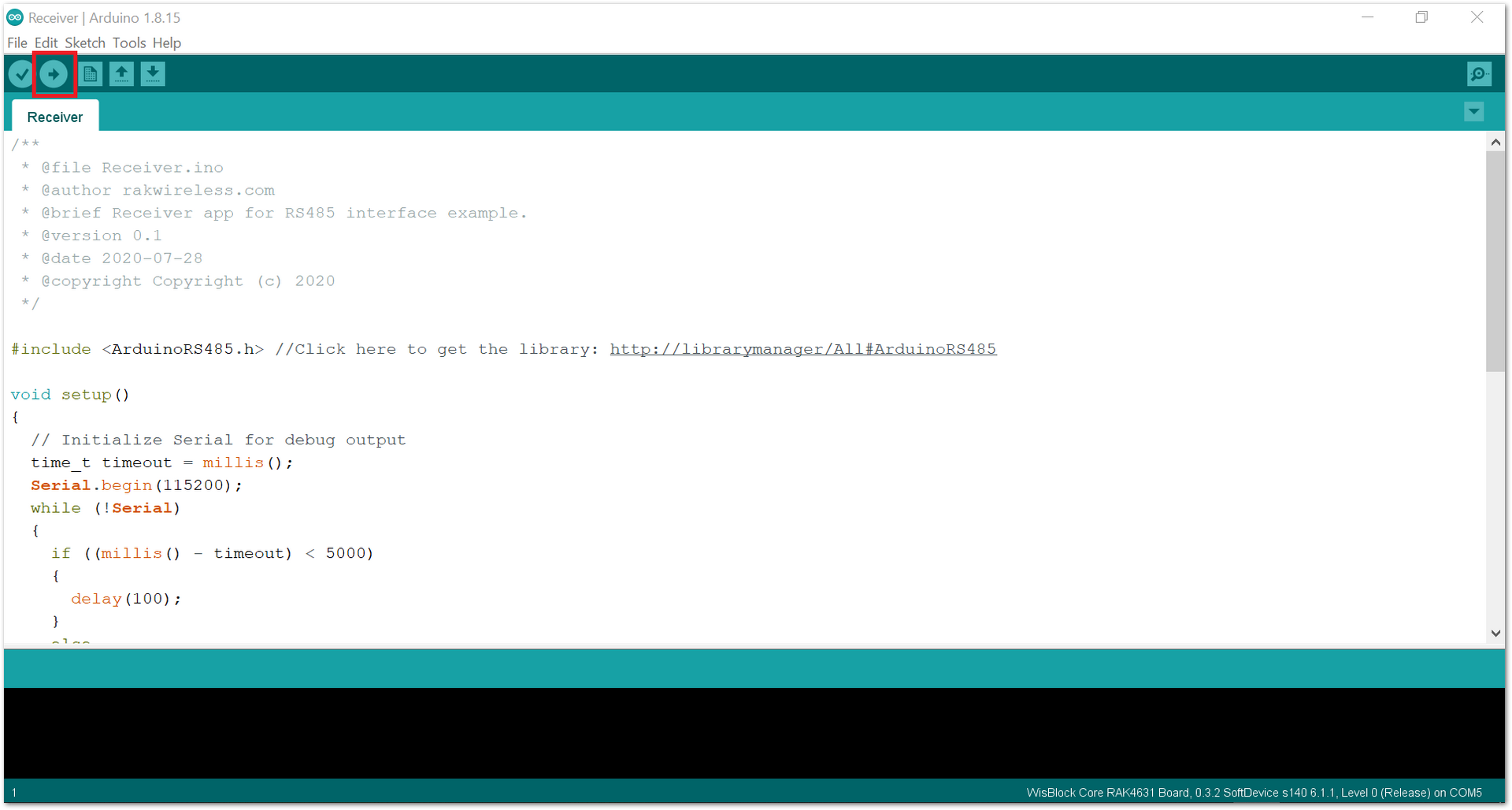 Figure 1: Uploading the RAK5802 example code
- When you successfully uploaded the example sketch, connect the board with the 'Receiver' code, open the Serial Monitor of the Arduino IDE, and power the 'Sender' board via USB or Battery to see the reading logs. If you see the logs, as shown in Figure 21, then your RAK5802 is properly communicating to the WisBlock core.
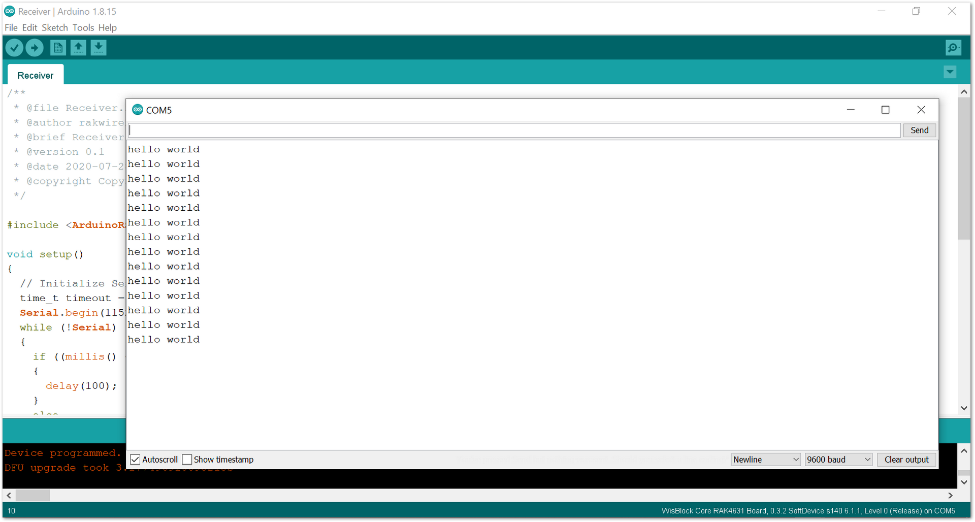 Figure 1: RAK5802 data logs from 'Sender' board