RAK4270 WisDuo Breakout Board Quick Start Guide
Prerequisites
Before proceeding with the installation and setup of the RAK4270 Breakout Board, ensure you have the following necessary items prepared:
Hardware Tools
- RAK4270 Breakout Board
- USB-UART Module (RAKDAP1 Tool)
- Gateway in Range for Testing
- Jumper Wires
- 3.3 V Battery Power Supply
- A Windows/Mac OS/Linux Computer
Software Tools
The bootloader of the RAK4270 Breakout Board is pre-installed during manufacturing, so flashing it is not required. If you suspect that the bootloader on your RAK4270 Breakout Board is damaged, contact RAK support via the RAKwireless forum. For instructions on upgrading the firmware of the device, refer to the miscellaneous section of this document.
Package Inclusions
- 1 pc - RAK4270 Breakout Board (chipset pre-soldered on the board)
- 1 pc - LoRa Antenna
List of Acronyms
| Acronym | Definition |
|---|---|
| DFU | Device Firmware Upgrade |
| JTAG | Joint Test Action Group |
| LoRa | Long Range |
| OTAA | Over-The-Air-Activation |
| ABP | Activation-By-Personalization (ABP) |
| TTN | The Things Network |
| TTS | The Things Stack |
Product Configuration
Interface with RAK4270 Breakout Board
RAK4270 Breakout Board can be configured using AT commands via the UART interface. You need a USB to UART TTL adapter to connect the RAK4270 board to the PC's USB port and a serial terminal tool.
Use the RAKDAP1 as the USB-to-UART interface device. The RAKDAP1 is compatible with other RAK modules and serves as both a debugging tool and firmware uploader. It is also highly recommended to use the RAK Serial Port Tool for easily sending AT commands and viewing console output responses.
Before powering on the RAK4270 Breakout Board, ensure that the LoRa antenna is properly installed. Failing to do so may result in damage to the board.
USB to UART
- Connect the RAK4270 Breakout Board to the USB-UART interface, as shown in Figure 1 and Figure 2.
UART1 is used for AT commands input as well as a firmware update. Check the RAK4270 Breakout Board Pin Definition on the datasheet for complete details.
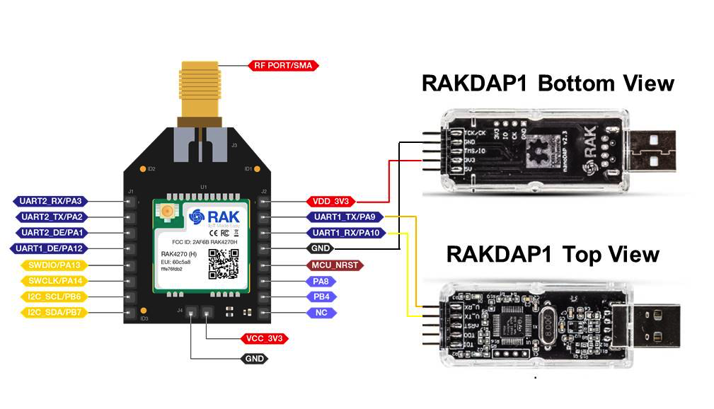 Figure 1: RAK4270 Breakout Board Connected to RAKDAP1 USB-UART Interface
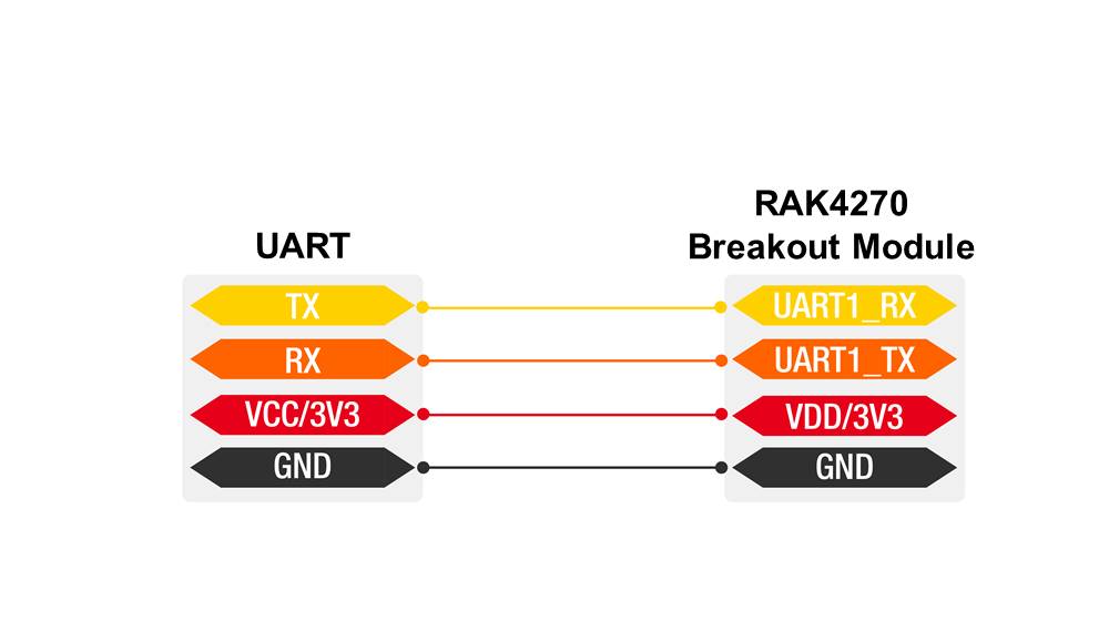 Figure 1: RAK4270 Breakout Board to USB Uart Module Connection
- Connect the USB-UART module to your Windows PC, open the RAK Serial Port Tool, and select the correct COM port and baud rate.
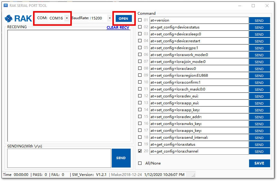 Figure 1: Correct Port Number and Baud rate
Connecting to The Things Stack (TTN V3)
This section will show how to connect the RAK4270 board to The Things Stack (TTN V3) platform.
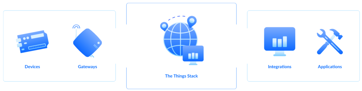 Figure 1: The Things Stack diagram
As shown in Figure 4, The Things Stack is an open-source LoRaWAN Network Server suitable for global, geo-distributed public and private deployments as well as for small, local networks. The architecture follows the LoRaWAN Network Reference Model for standards compliancy and interoperability. This project is actively maintained by The Things Industries.
LoRaWAN is a protocol for low-power wide-area networks. It allows large-scale Internet of Things deployments where low-powered devices efficiently communicate with Internet-connected applications over long-range wireless connections.
The RAK4270 Breakout Board can function as a device within this ecosystem. This section demonstrates how easily data can be sent to The Things Stack using the LoRaWAN protocol. To accomplish this, ensure the RAK4270 board is within the coverage area of a LoRaWAN gateway connected to The Things Stack server.
Register for TTN and Create LoRaWAN Applications
Before starting, navigate to the The Things Network platform and select a cluster, as shown in Figure 5. The Things Industries periodically adds new clusters, so choose the one closest to your location. In this guide, Europe 1 is selected as an example.
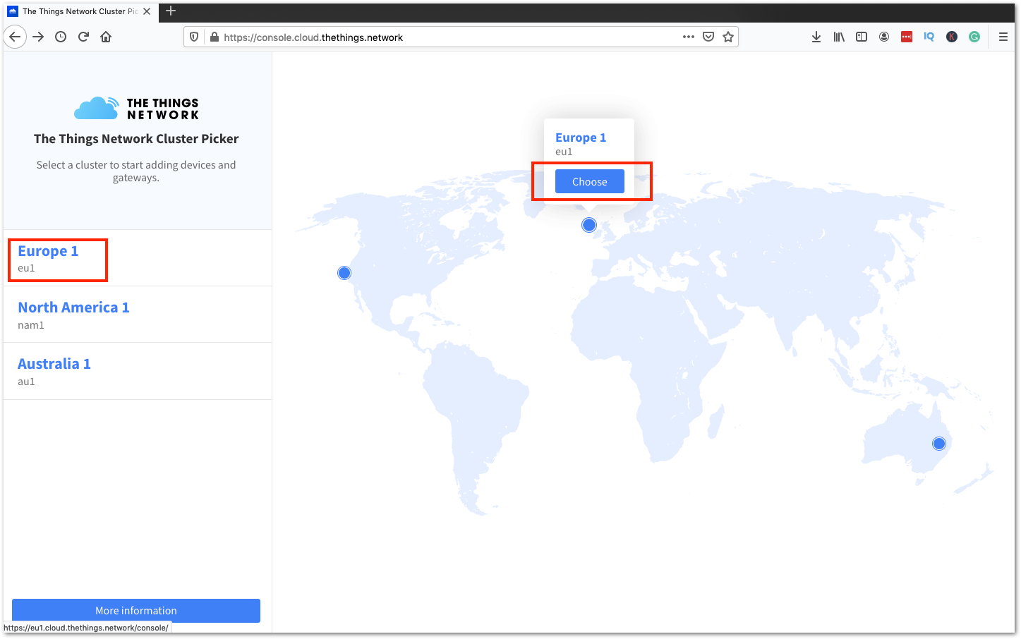 Figure 1: Select Cluster in TTN V3
Use your existing login credentials from TTN V2 if you have an account. Otherwise, create a new account.
- To register as a new user to TTN, click on Login with The Things ID, then select register on the next page, as shown in Figure 6 and Figure 7. Fill in all the necessary details and activate.
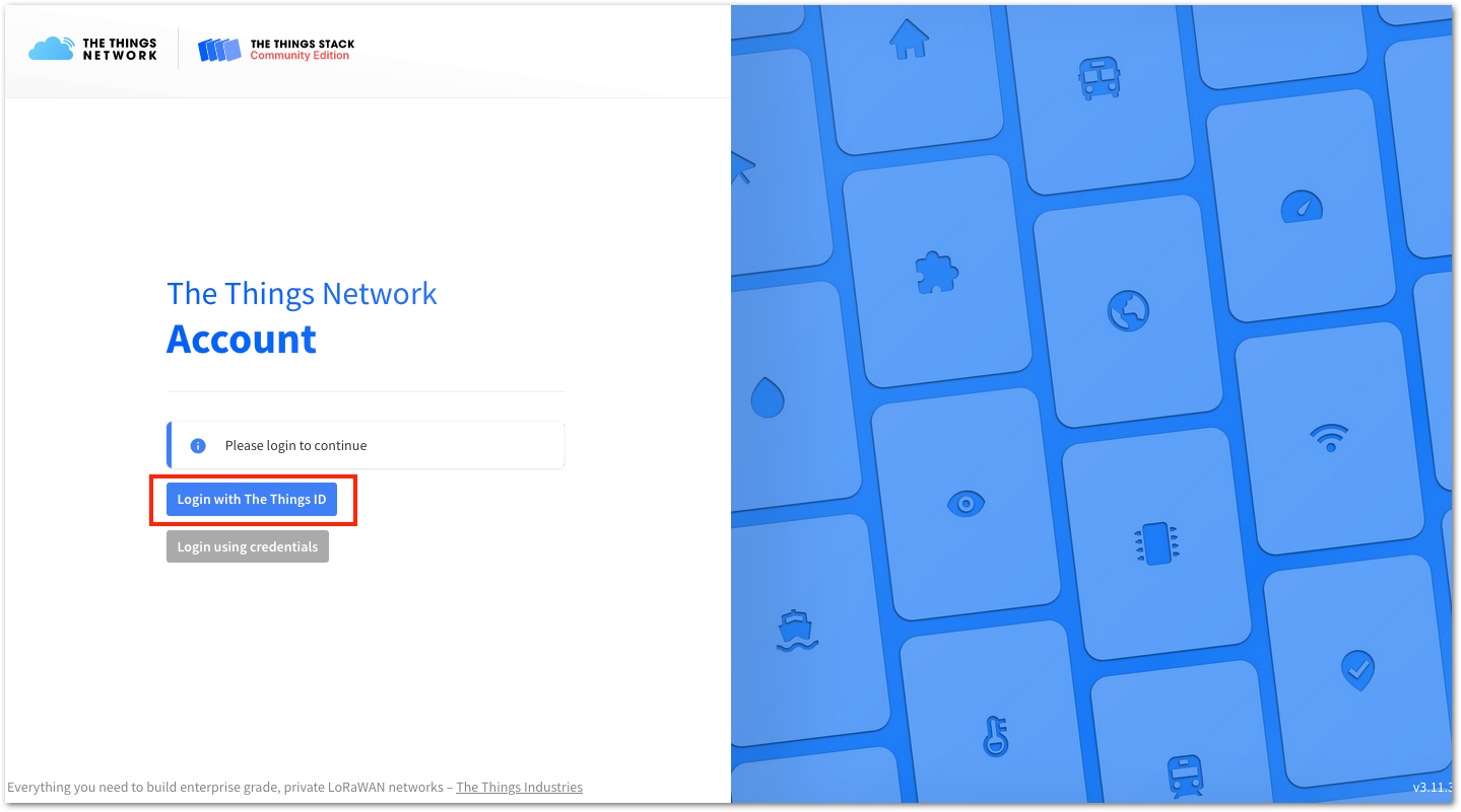 Figure 1: Log in using TTN account
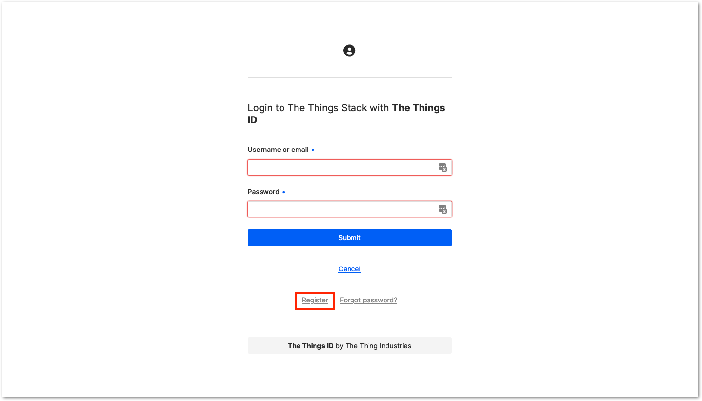 Figure 1: Registration of new account
- Log in on the platform using your username/email and password then click Submit, as shown in Figure 8.
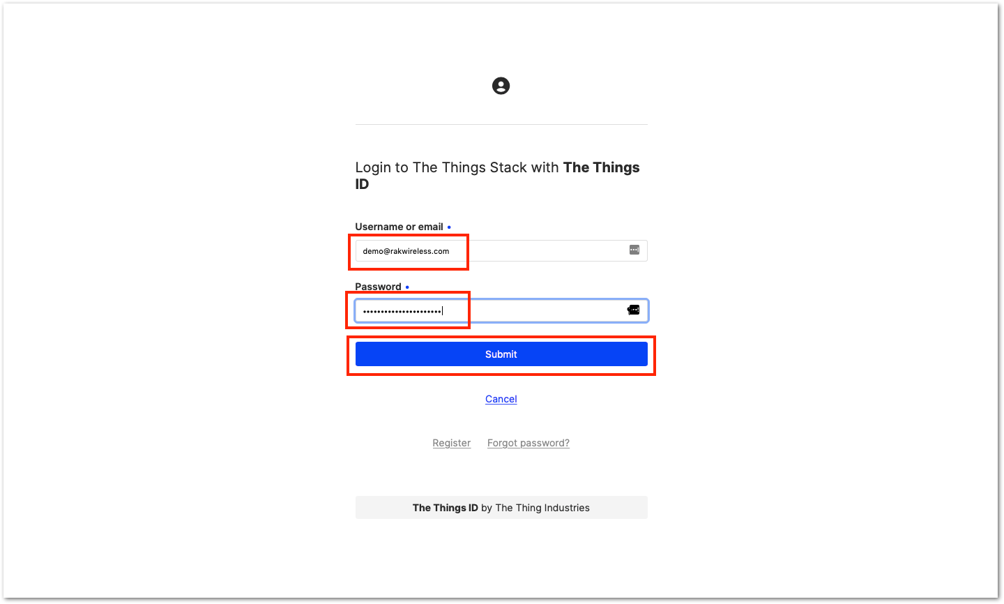 Figure 1: Log in to TTN platform
- Click Authorize to proceed.
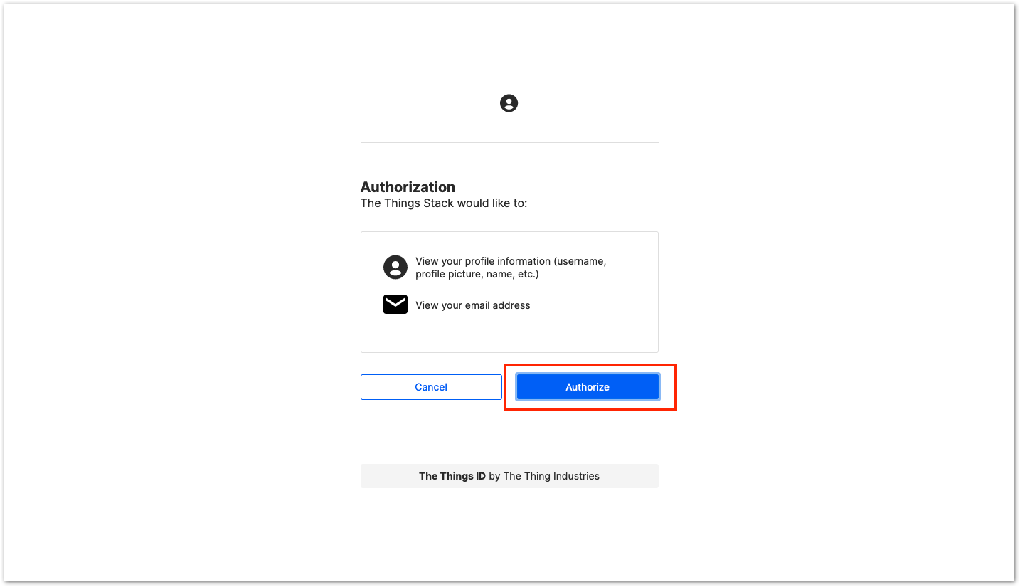 Figure 1: Authorization to TTN
- Click Create an application.
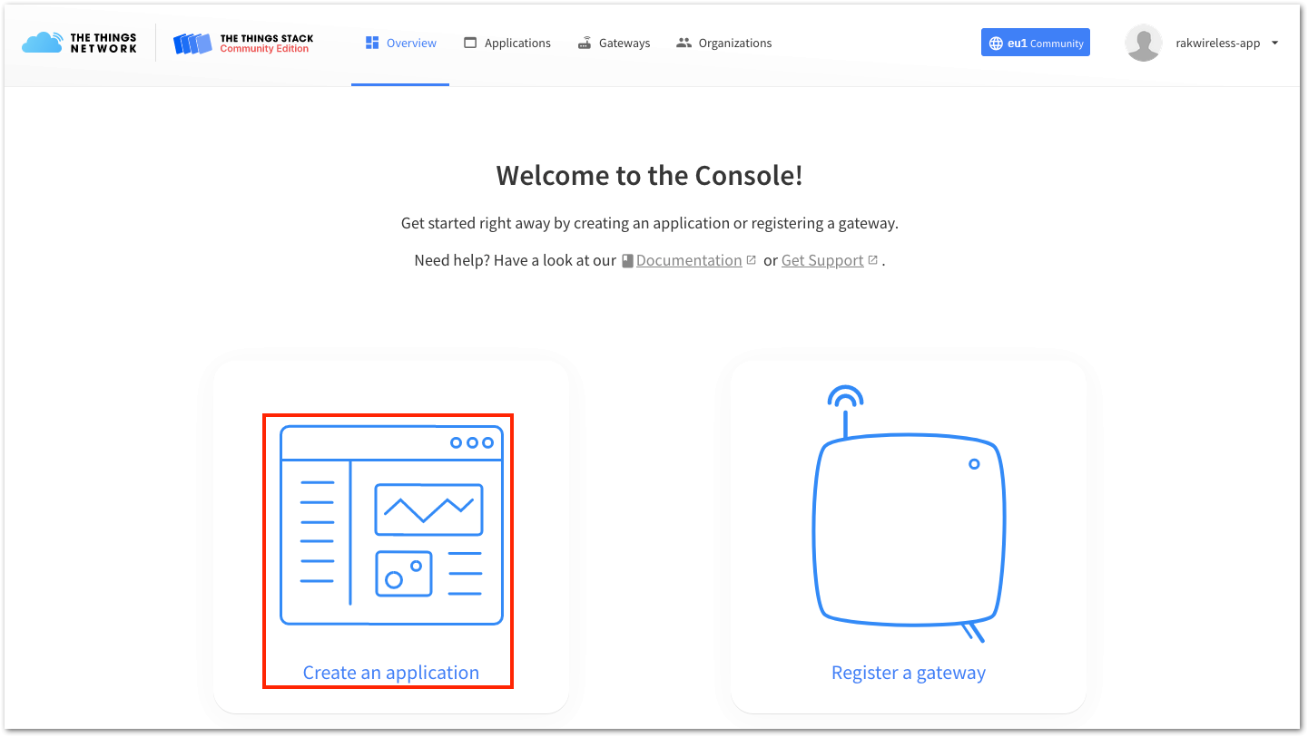 Figure 1: Create TTN application for your LoRaWAN devices
- To register an application, first enter the required details and information about your application, then click Create application.
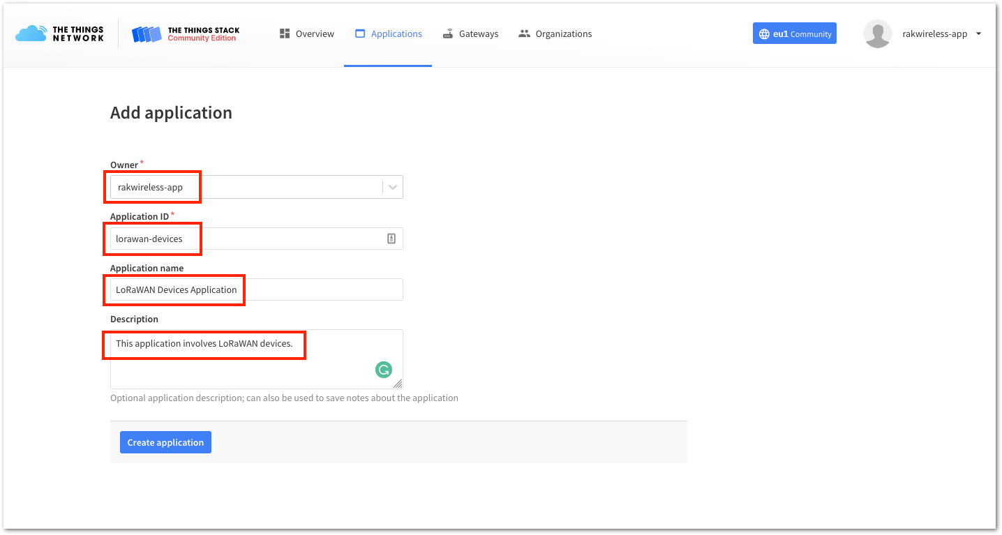 Figure 1: Details of the TTN application
The next step is to add end-devices to your The Things Stack application. LoRaWAN specification enforces that each end device has to be personalized and activated. Activation can be done either via Over-The-Air-Activation (OTAA) or Activation-By-Personalization (ABP).
-
Ensure that you are within the coverage of a LoRaWAN gateway registered with The Things Stack (TTN V3). Without coverage from such a gateway, you will not be able to activate any device registered in your application.
-
If no LoRaWAN gateway coverage is available in your location, RAKwireless offers LoRaWAN gateways that can be connected to The Things Stack (TTN V3).
The Things Stack OTAA Device Registration
- Go to your application console to register a device. To start adding an OTAA end-device, click + Add end device, as shown in Figure 12.
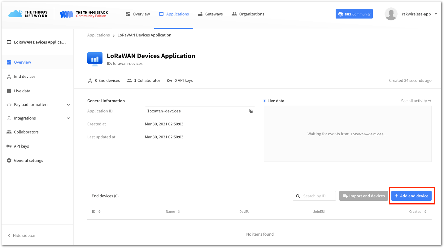 Figure 1: Add end device
- To register the module, first click Manually. Then, configure the activation method by selecting Over the Air Activation (OTAA) and a compatible LoRaWAN version. Finally, click the Start button, as shown in Figure 13 and Figure 14.
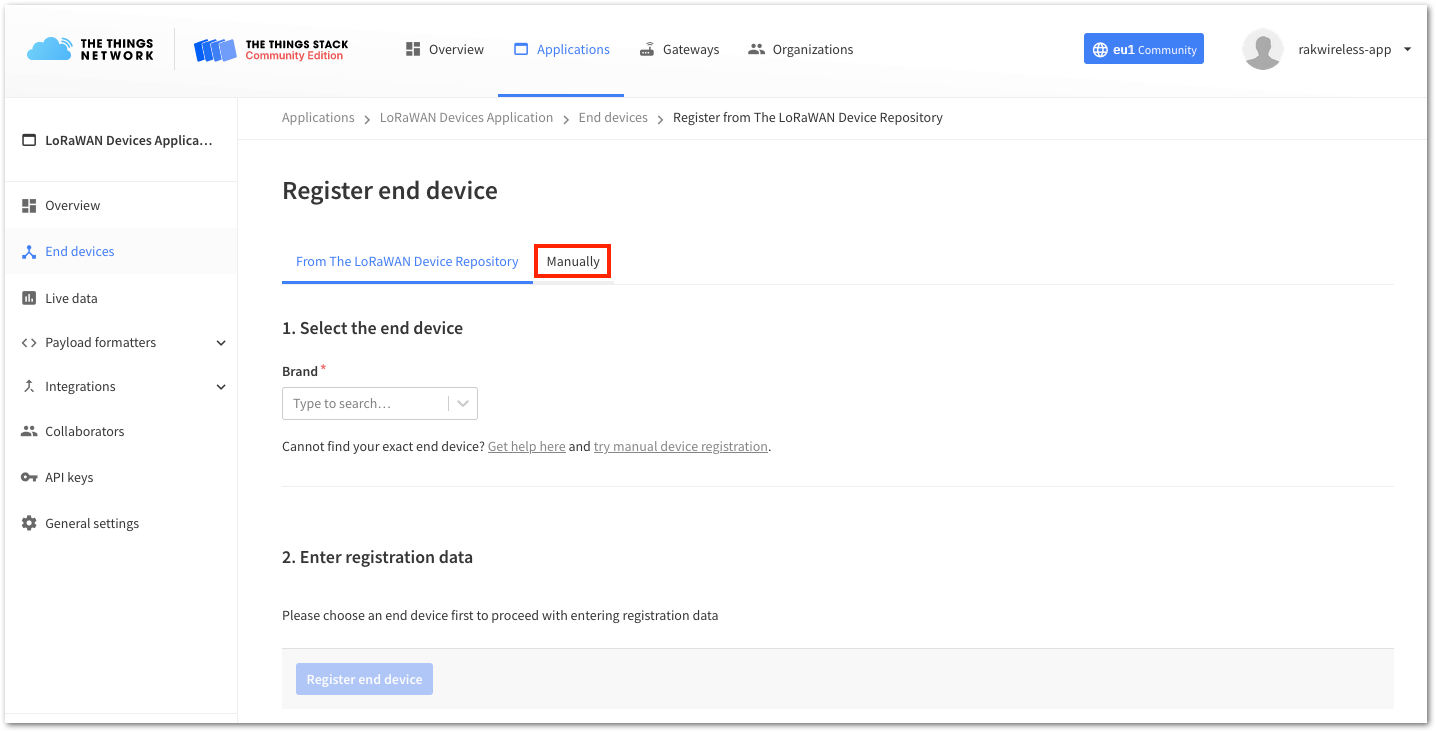 Figure 1: Manually register device to The Things Stack
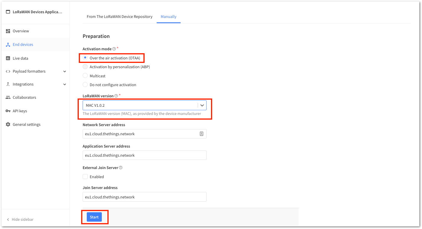 Figure 1: Device activation configuration
- Enter a unique End Device ID and the EUIs (DevEUI and AppEUI), as shown in Figure 15. Check if your module has a DevEUI on a sticker or a QR code that you can scan, and use this as the unique DevEUI for the device.
Optionally, add a descriptive End device name and End device description about your device.
- After entering all the details, click Network layer settings to proceed to the next step.
It is advisable to use a meaningful End device ID, End device name, and End device description that will match your device purpose. The End device ID rak-device is for illustration purposes only.
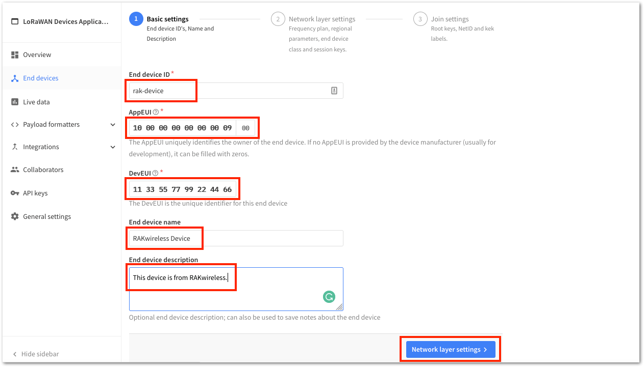 Figure 1: OTAA Device Information
- Configure the Frequency plan, compatible Regional Parameter version, and the supported LoRaWAN class. Then, click Join settings to continue.
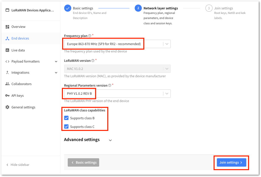 Figure 1: OTAA Configuration
- To generate the AppKey, click the Generate button. Then, click Add end device to complete the device registration process.
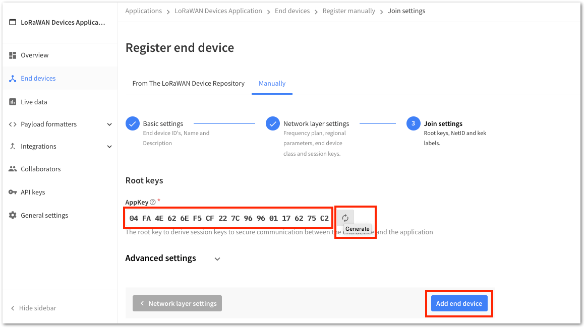 Figure 1: OTAA AppKey generation and device registration
You should now be able to see the device on The Things Stack console, as shown in Figure 18.
-
The AppEUI, DevEUI, and AppKey are required parameters to activate your LoRaWAN end device using OTAA. For security reasons, the AppKey is hidden by default but can be revealed by clicking the Show button. You can also quickly copy these parameters using the Copy button.
-
The three OTAA parameters on The Things Stack device console are MSB by default.
-
These parameters are always accessible on the device console page, as shown in Figure 18.
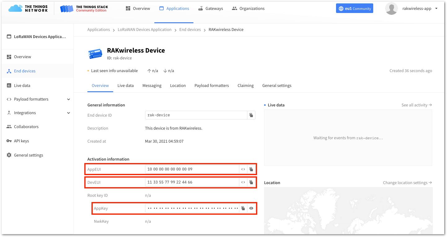 Figure 1: OTAA device successfully registered to The Things Stack
RAK4270 OTAA Configuration for The Things Stack
The RAK4270 Breakout Board supports a series of AT commands to configure its internal parameters and control the functionalities of the module. To set up the RAK4270 board to join The Things Stack using OTAA, start by connecting the RAK4270 board to the Computer (see Figure 1) and open the RAK Serial Port Tool. Wait for the communication to start. It is recommended to test the serial communication and verify the current configuration by sending either of these two AT commands:
at+set_config=device:restart
at+version
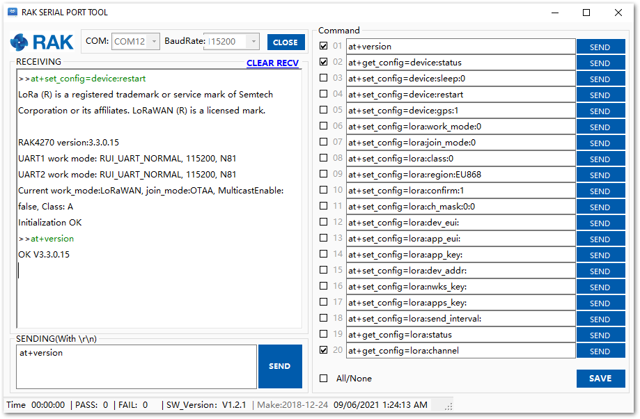 Figure 1: AT Command response
As an example, these are the list of the parameters you need to configure in RAK4270:
- LoRa join mode: OTAA
- LoRa class: Class A
- LoRa region: EU868
- Device EUI: 1133557799224466
- Application EUI: 1000000000000009
- Application Key: 04FA4E626EF5CF227C969601176275C2
- Set the LoRa join mode to OTAA.
at+set_config=lora:join_mode:0
- Set the LoRa class to Class A.
at+set_config=lora:class:0
- Set the frequency/region to EU868.
- Refer to the RAK4270 Breakout Board Datasheet for the list of supported frequencies.
at+set_config=lora:region:EU868
- Set the Device EUI.
at+set_config=lora:dev_eui:1133557799224466
- Set the Application EUI.
All zero value Application EUI at+set_config=lora:app_eui:0000000000000000 is not supported and will return error.
at+set_config=lora:app_eui:1000000000000009
- Set the Application Key.
at+set_config=lora:app_key:04FA4E626EF5CF227C969601176275C2
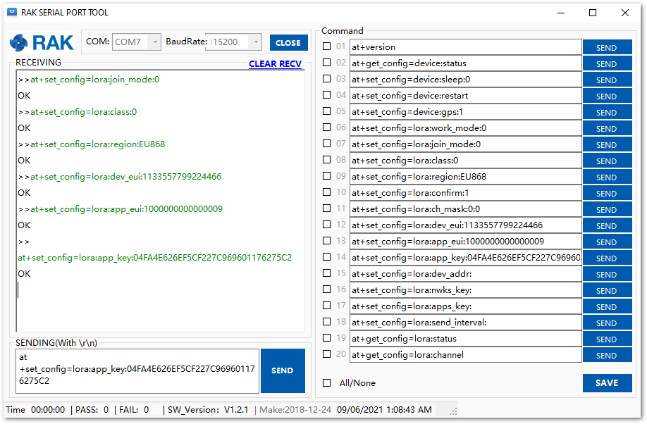 Figure 1: Configure LoRa Parameters
After configuring, reset your RAK4270 Breakout Board to save the parameters.
- Join in OTAA mode.
at+join
After 5 or 6 seconds, if the request is successfully received by a LoRa gateway, then you should see the messages shown in Figure 21.
- Try to send a message from the RAK4270 board.
at+send=lora:2:1234567890
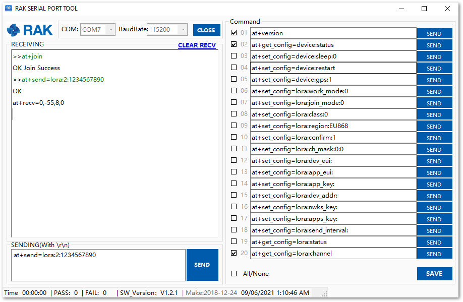 Figure 1: OTAA Test Sample Data Sent via RAK Serial Port Tool
You can see the data sent by the RAK4270 board on The Things Stack platform, as shown in Figure 22.
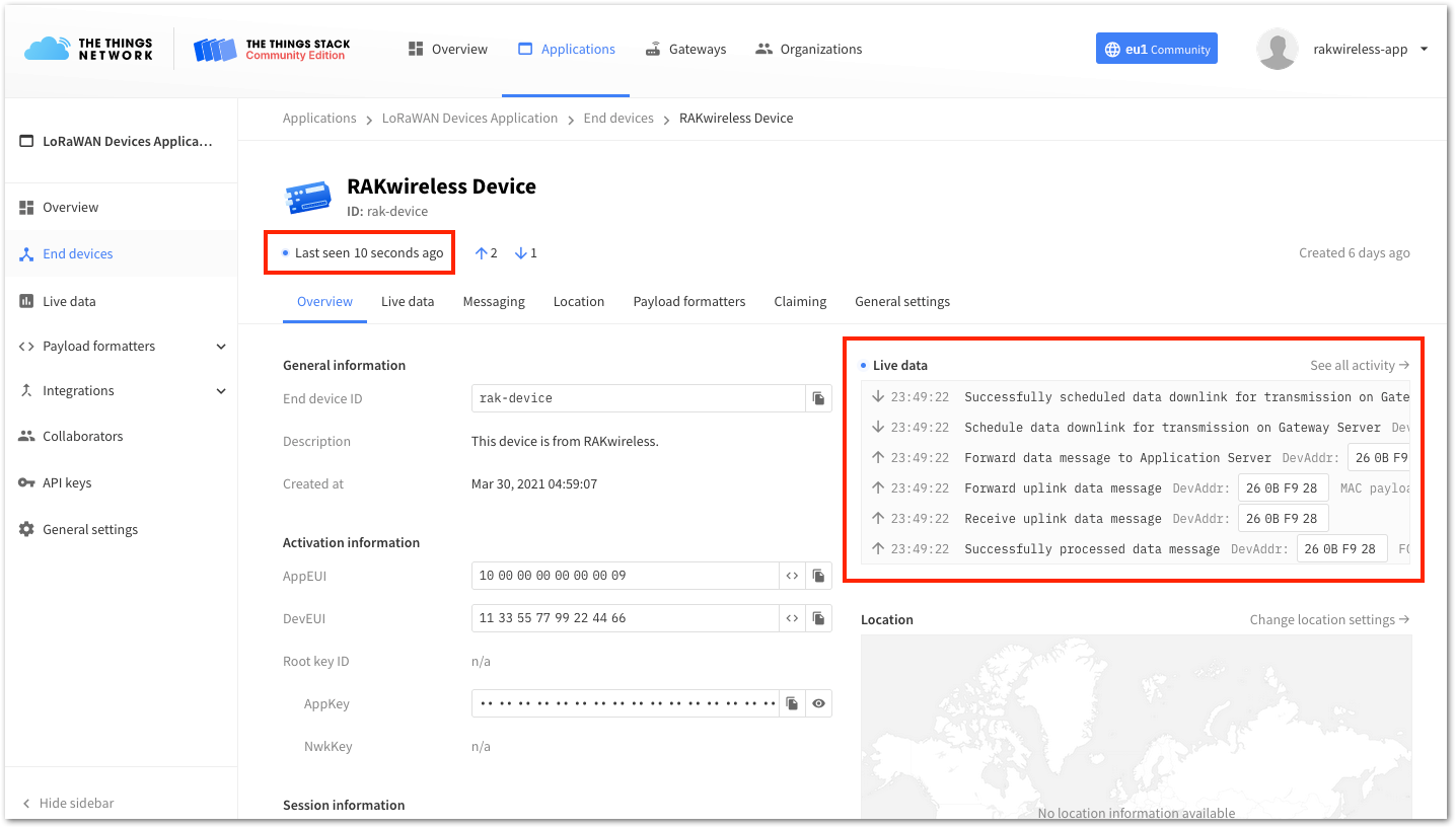 Figure 1: OTAA Test Sample Data Sent Viewed in The Things Stack
The Things Stack ABP Device Registration
- To register an ABP device, open your application console and select the application to which you want to add the device. Then, click + Add end device, as shown in Figure 23.
Figure 1: Add end device- To register the module, click Manually, then configure the activation method by selecting Activation by personalization (ABP), compatible LoRaWAN version, and click Start button, as shown in Figure 24 and Figure 25.
Figure 1: Add end device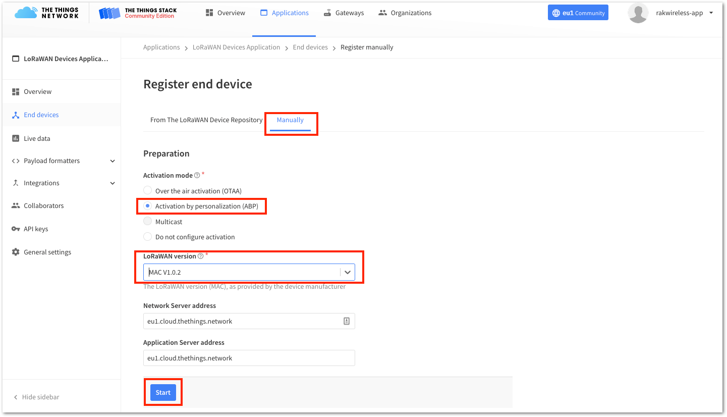 Figure 1: Manually register device to The Things Stack
- Enter a unique End Device ID and DevEUI, as shown in Figure 26. Check if your module has a DevEUI on a sticker or a QR code that you can scan, and use this as the unique DevEUI for the device.
Optionally, add a descriptive End device name and End device description about your device.
- After entering all the details, click Network layer settings to proceed to the next step.
It is advisable to use a meaningful End device ID, End device name, and End device description that will match your device purpose. The End device ID rak-device-abp is for illustration purposes only.
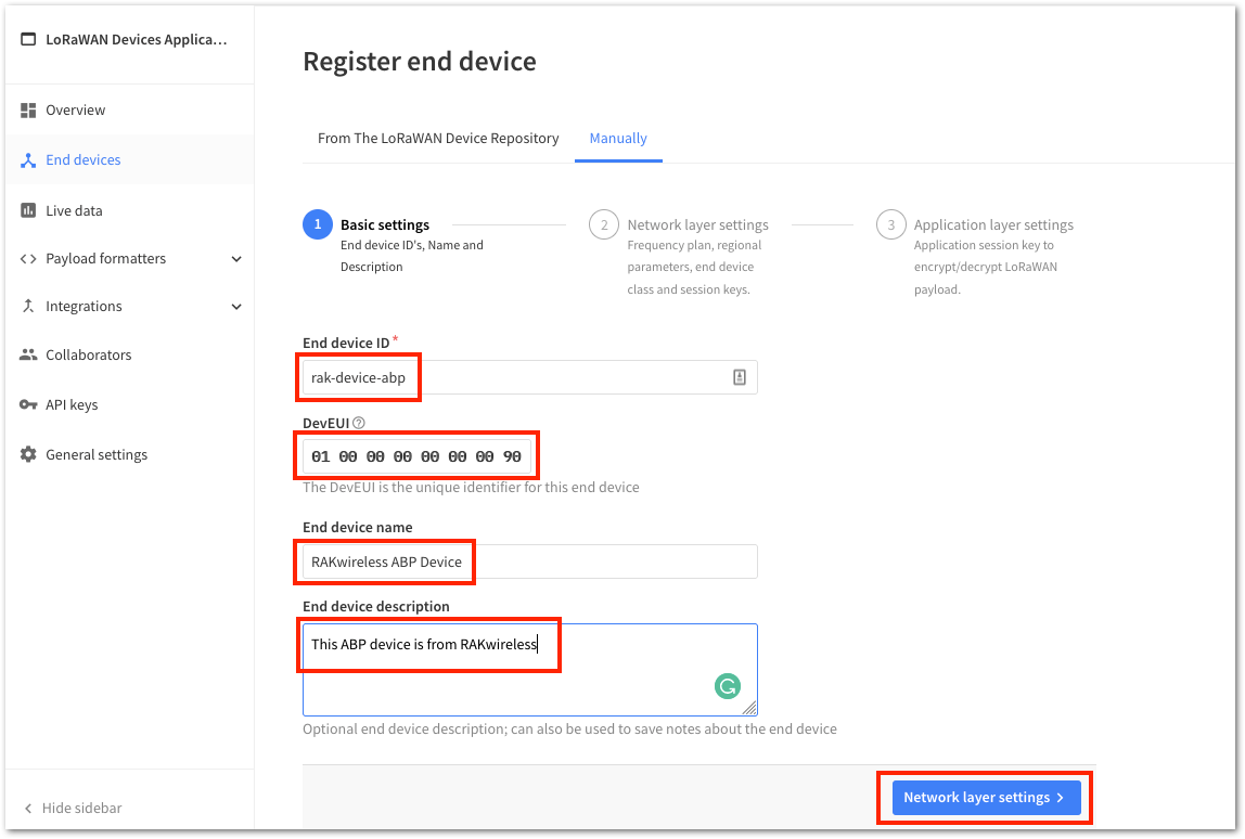 Figure 1: Device Information
- Configure the Frequency plan, compatible Regional Parameter version, and supported LoRaWAN class. For an ABP device, generate the Device Address and NwkSKey (Network Session Key). Then, click Application layer settings to proceed.
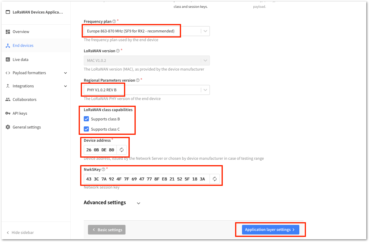 Figure 1: ABP Configuration in The Things Stack
- To generate the AppSKey, click the Generate button. Then, click Add end device to complete the device registration process.
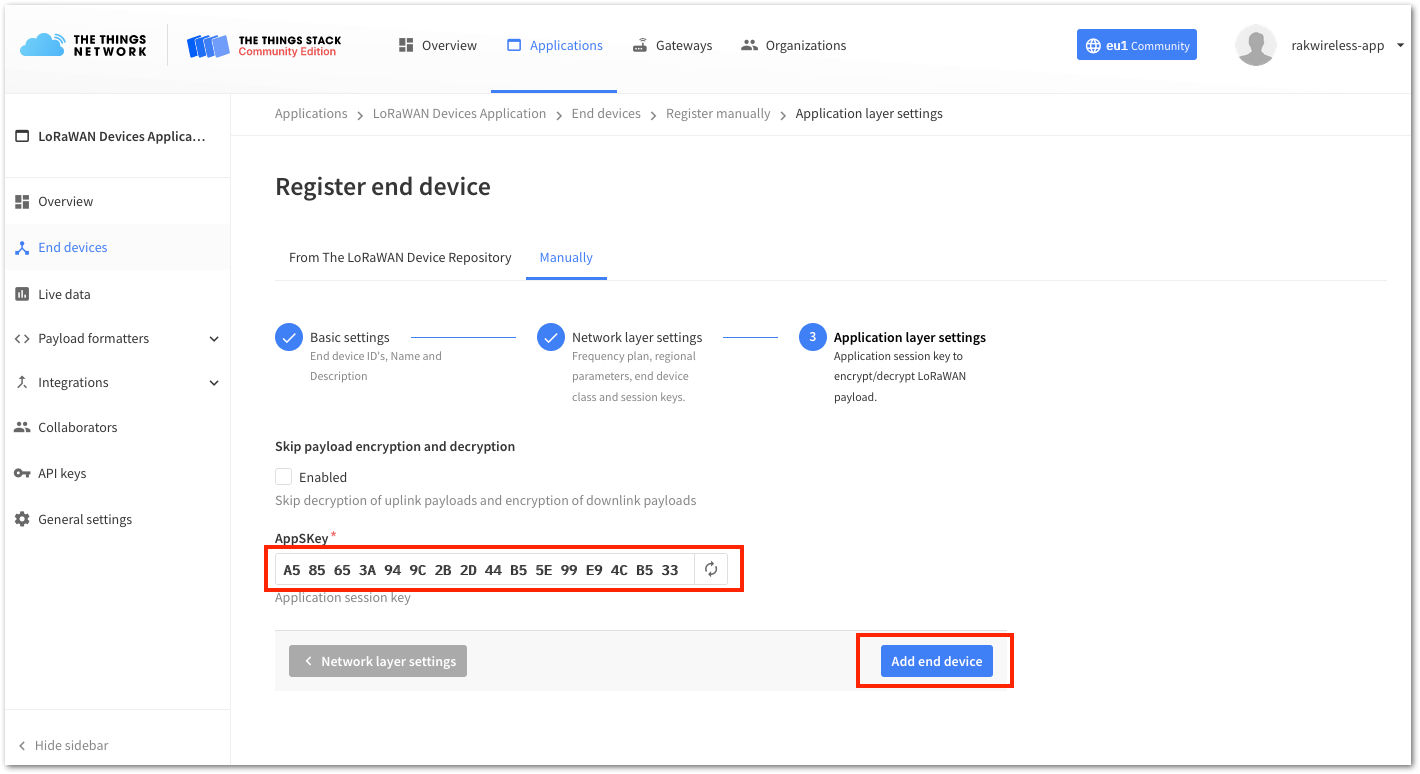 Figure 1: ABP Configuration in The Things Stack
You should now be able to see the device on The Things Stack console, as shown in Figure 29.
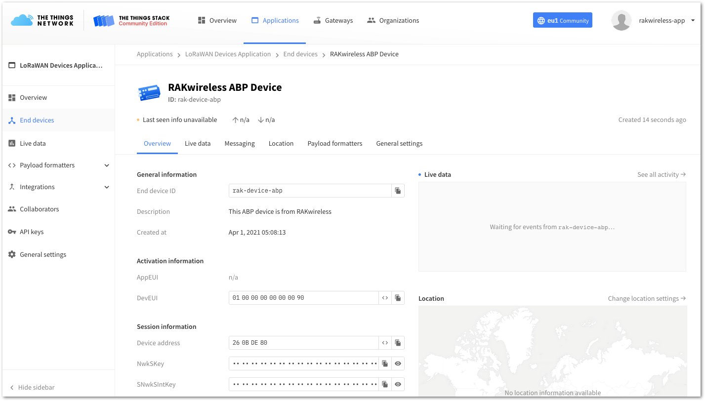 Figure 1: RAK4270 registered at The Things Stack
RAK4270 ABP Configuration for The Things Stack
To set up the RAK4270 Breakout Board to join The Things Stack using ABP, start by connecting the RAK4270 board to the Computer (see Figure 1) and open the RAK Serial Port Tool. It is recommended to test the serial communication by sending either of these two AT commands:
at+set_config=device:restart
at+version
As an example, these are the list of the parameters you need to configure in RAK4270:
- LoRa join mode: ABP
- LoRa class: Class A
- LoRa region: EU868
- Device address: 260BDE80
- Network Session Key: 433C7A924F7F6947778FE821525F183A
- Application Session Key: A585653A949C2B2D44B55E99E94CB533
- Set the LoRa join mode to ABP.
at+set_config=lora:join_mode:1
- Set the LoRa class to Class A.
at+set_config=lora:class:0
- Set the frequency/region to EU868.
- Refer to the RAK4270 Breakout Board Datasheet for the list of supported frequencies.
at+set_config=lora:region:EU868
- Set the Device Address.
at+set_config=lora:dev_addr:260BDE80
- Set the LoRa Network Session Key.
at+set_config=lora:nwks_key:433C7A924F7F6947778FE821525F183A
- Set the LoRa Application Session Key.
at+set_config=lora:apps_key:A585653A949C2B2D44B55E99E94CB533
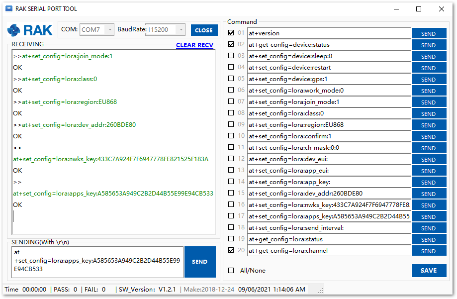 Figure 1: AT Command for ABP LoRa parameters via RAK Serial Port Tool
After configuring all the parameters, reset the RAK4270 Breakout Board to save the configuration
- Join in ABP mode.
at+join
In ABP mode, LoRaWAN does not require the device to join a network before sending a LoRaWAN packet. However, to maintain the consistency of the internal states of the RAK4270 board's firmware, the at+join command must still be sent. In this case, the firmware will respond almost immediately with OK.
- Try to send data from the RAK4270 to The Things Network in ABP mode.
at+send=lora:2:1234567890
You can see the data sent by the RAK4270 board on The Things Stack device console Live data section and the Last seen info should be few seconds ago.
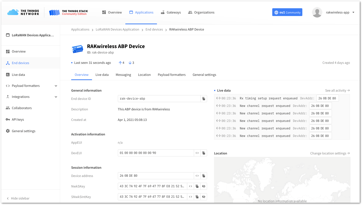 Figure 1: OTAA Test Sample Data Sent Viewed in The Things Stack
Connect with ChirpStack
ChirpStack, formerly known as the LoRaServer project, offers open-source components for creating LoRaWAN networks. Similar to The Things Network (TTN), the RAK4270 Breakout Module operates at the periphery, transmitting data to backend servers via a LoRa gateway. For more information, visit theofficial ChirpStack website.
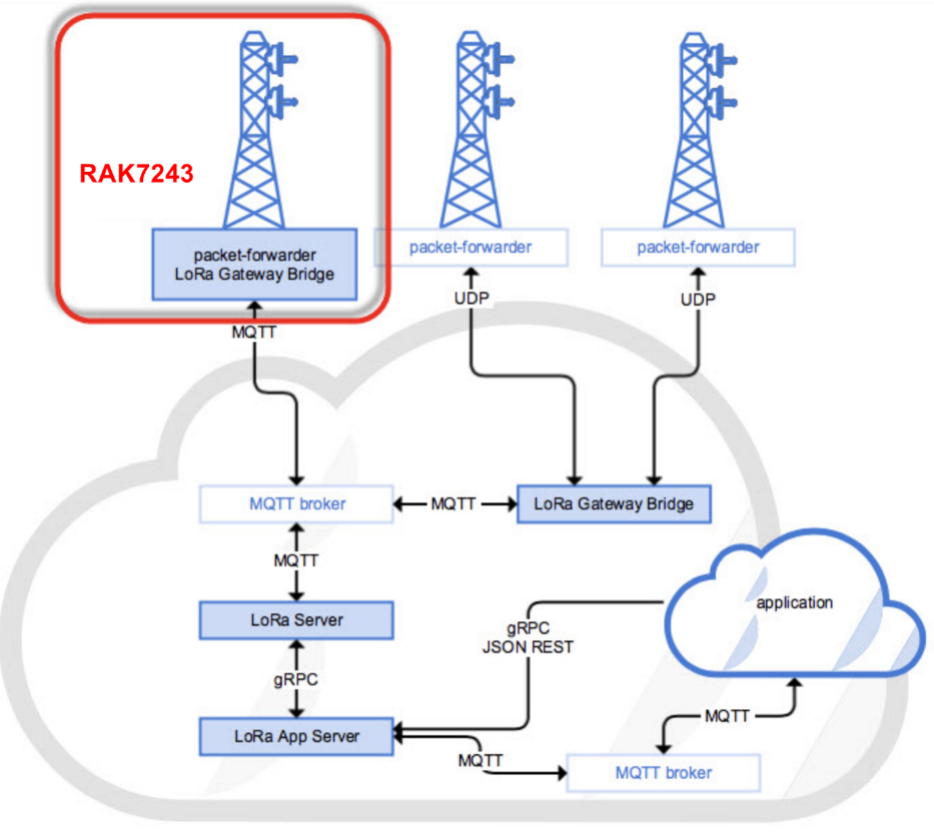 Figure 1: RAK4270 Breakout Board in the Context of the ChirpStack Platform
This document assumes that you are using a RAK Gateway with its built-in ChirpStack or the RAK Cloud Testing ChirpStack. Additionally, ensure that the RAK Gateway with ChirpStack is successfully configured. For detailed guidance, refer to the relevant RAK documentation.
In this section, you need the following requirements:
- Ensure that the ChirpStack online gateway is operational and that the frequency band of the nodes matches the frequency band of the gateway in use.
- The RAK Serial Port Tool provided by RAK
- RAK4270 Breakout Board
The frequency band used in the test is EU868, use the high-frequency version of the RAK4270 Breakout Board.
Before starting, decide whether to use OTAA or ABP mode to register the device with the network server.
Sign up and loginLog in to the ChirpStack server using your username and password.
Create a New Application
- Go to the Application section, as shown in Figure 35.
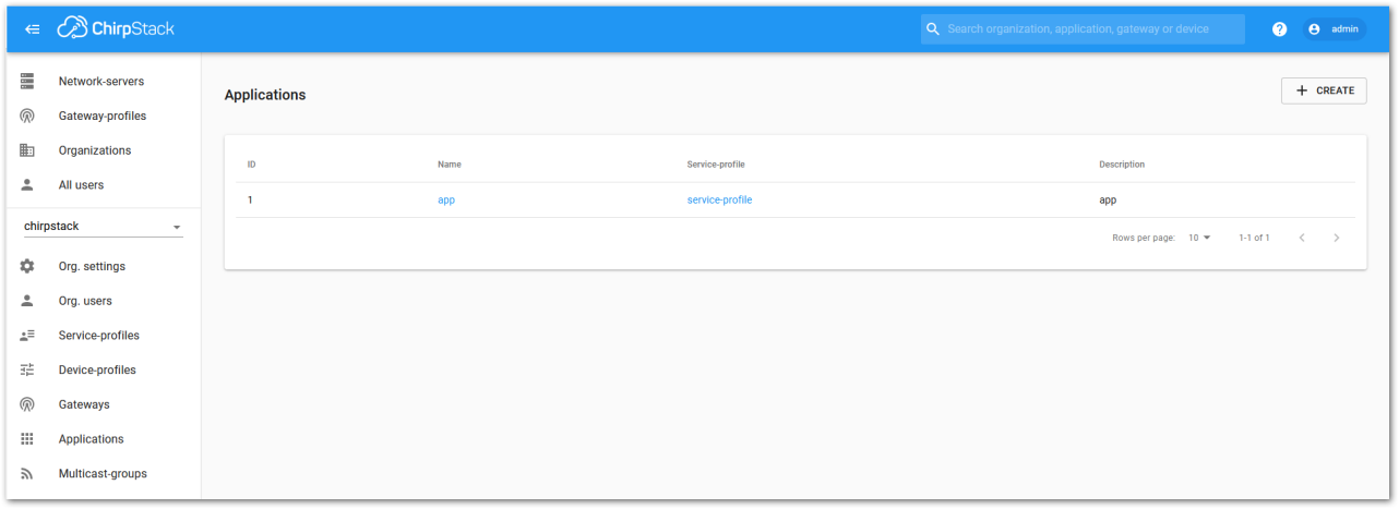 Figure 1: Application Section
- For this setup, create a new Application by clicking on the “CREATE” button, and filling the required parameters, as shown in Figure 36 and Figure 37.
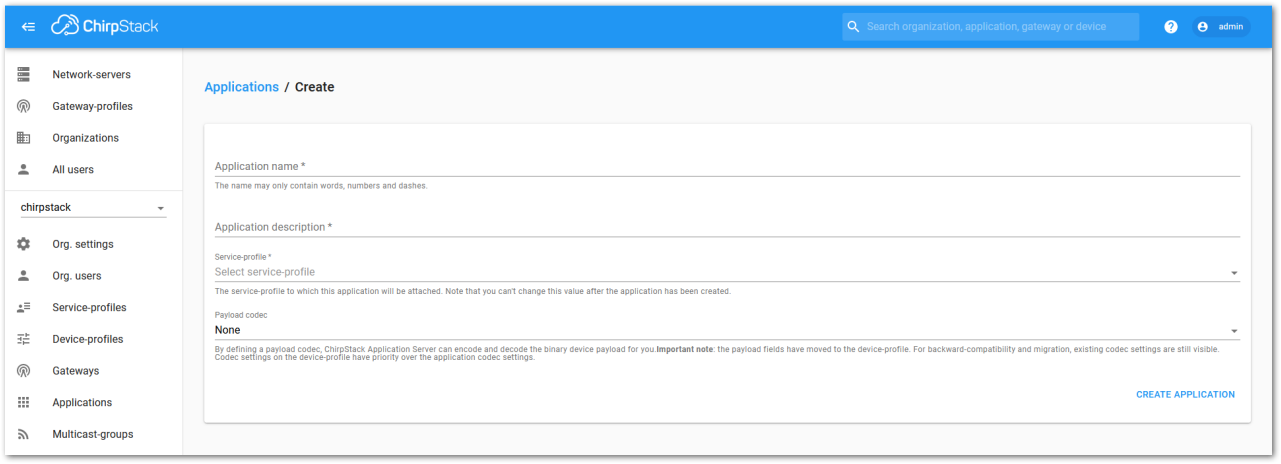 Figure 1: Creating a New Application
- For this setup, create an Application named “rak_node_test”.
ChirpStack LoraServer supports multiple system configurations, with only one by default.
- The Service Profile field is used to select the system profile.
- The Payload Codec Specifies the parsing method for processing payload data, such as parsing LPP format data.
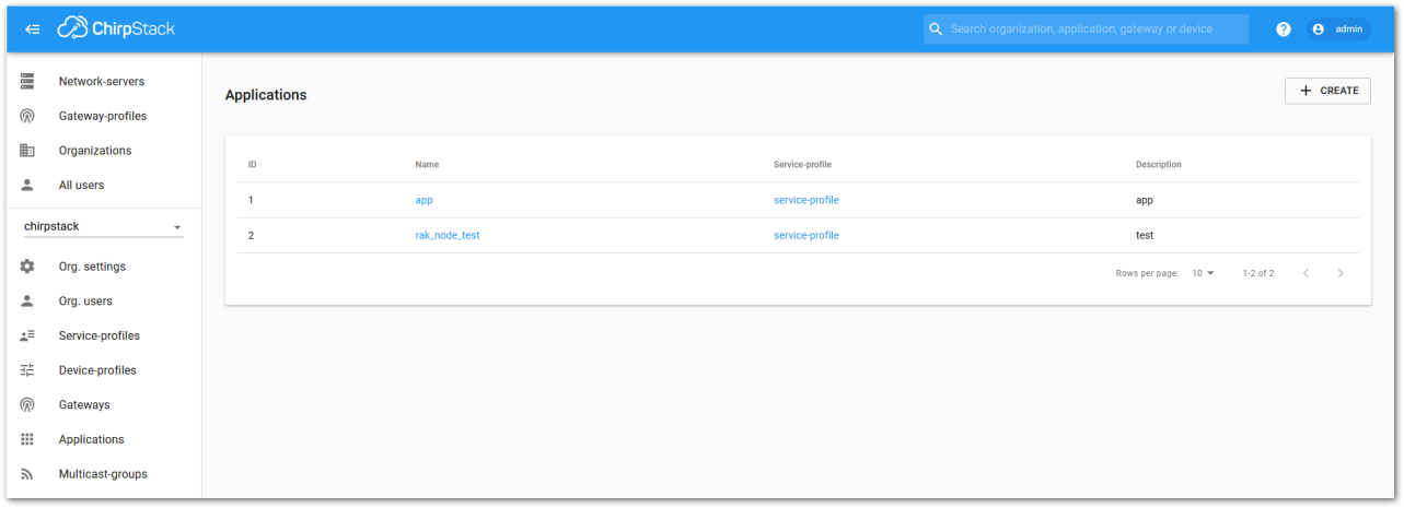 Figure 1: Fill in Parameters of an Application
-
Choose the Application created in the previous step, then select the DEVICES tab, as shown in Figure 38 and Figure 39.
-
Once done, click CREATE APPLICATION.
 Figure 1: List of Applications Created
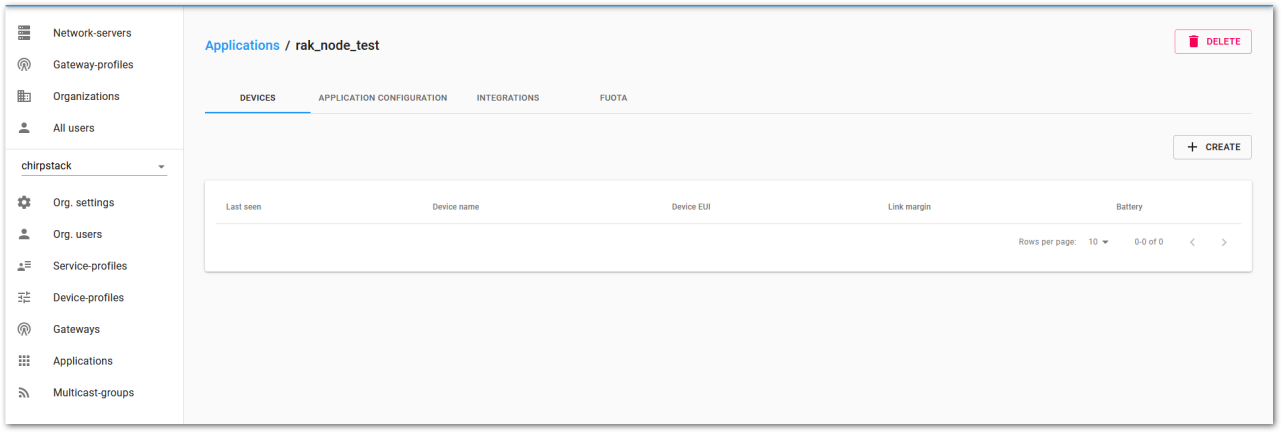 Figure 1: Device Tab of an Application
- Once inside of the DEVICE tab, create a new device (LoRa node) by clicking on the + CREATE button.
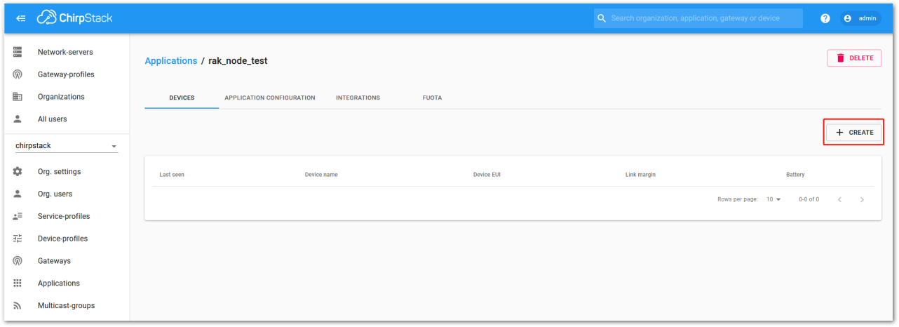 Figure 1: Add a New Device
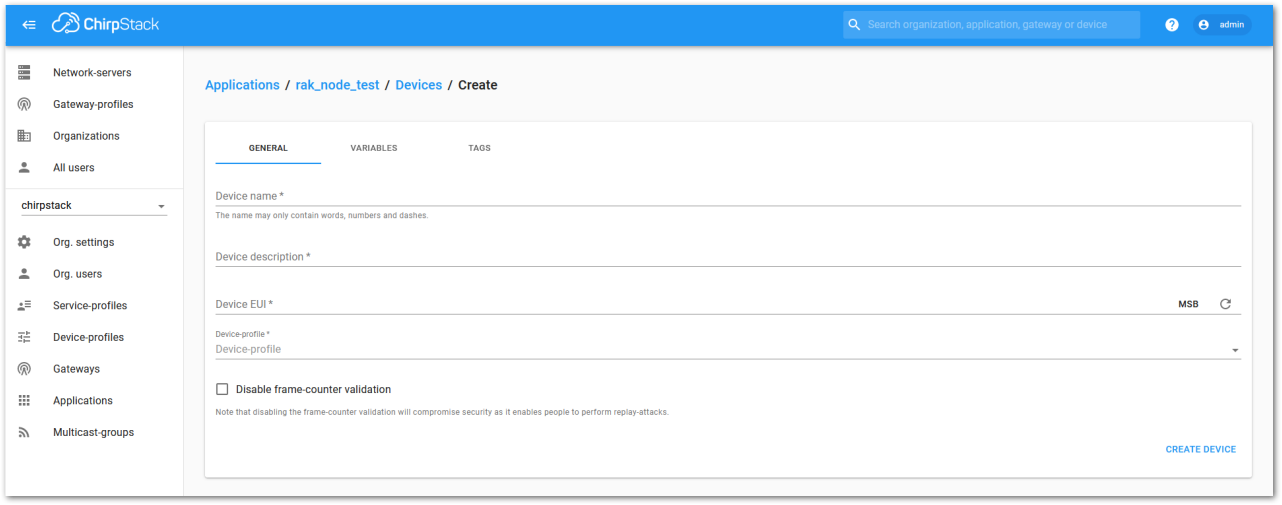 Figure 1: New Device Registration Form
- After creating the node, fill in the required details. You can either generate a Device EUI automatically by clicking the icon or manually enter a valid Device EUI in the edit box.
Fill in the parameters requested:
- Device name and Device description: These are descriptive texts about your device.
- Device EUI: This interface lets you generate a Device EUI automatically by clicking the red-highlighted icon in Figure 42. Alternatively, you can manually enter a specific Device EUI directly into the form.
- Device Profile:
- If you want to join in OTAA mode, select DeviceProfile_OTAA.
- If you want to join in ABP mode, select DeviceProfile_ABP.
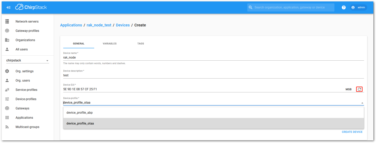 Figure 1: Generate a New Device EUI
LoRaWAN Join Mode
In LoRaWAN, a node can connect to the network using one of two methods, collectively referred to as Join Mode. The two supported modes are OTAA (Over the Air Activation) and ABP (Activation by Personalization). This section explains the configuration process for both modes, covering both the platform side and the node side.
OTAA Mode
Configure the OTAA Mode on the Platform
- If DeviceProfile_OTAA is selected, as shown in Figure 43, an Application Key must be created for the device after it is successfully created.
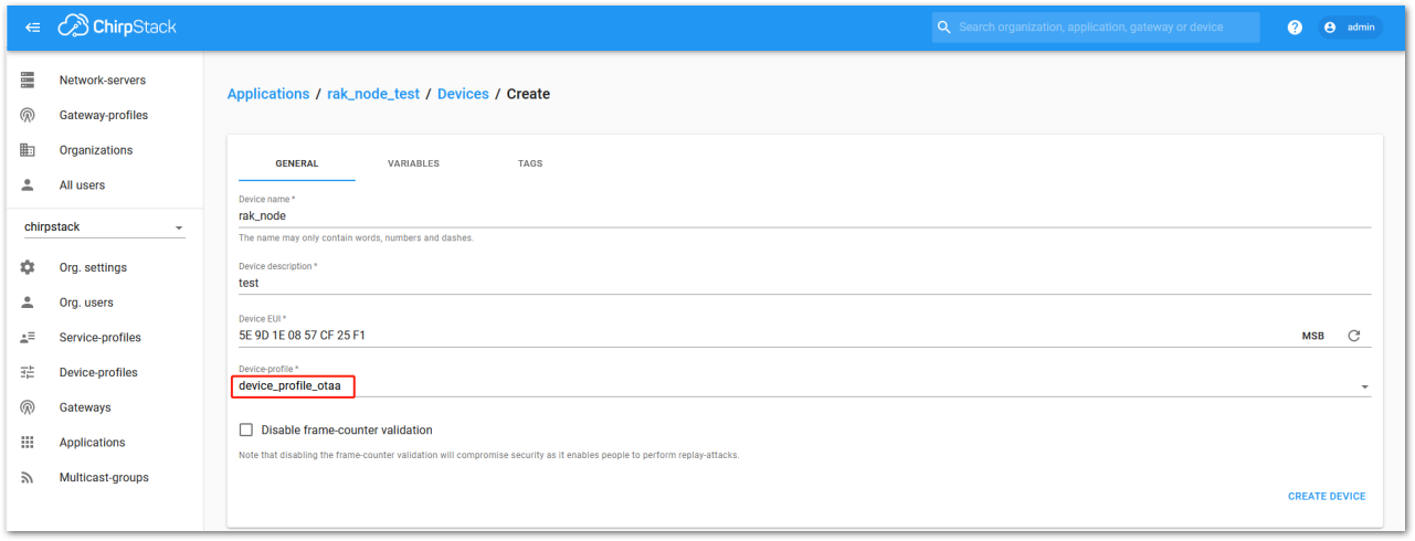 Figure 1: Chirpstack OTAA Activation
- A previously created Application Key can be entered here, or a new one can be generated automatically by clicking the icon highlighted in red in Figure 44.
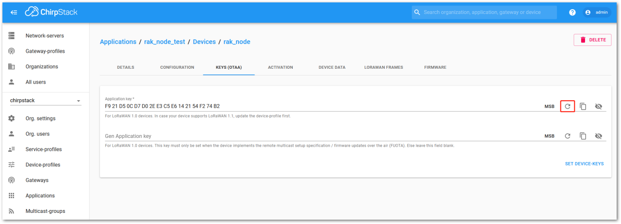 Figure 1: Chirpstack OTAA Set Device Keys
- Once the Application Key is added to the form, the process can be finalized by clicking on the SET DEVICE-KEYS button.
- The newly created device will appear in the DEVICES tab. Key parameters, such as the Device EUI, will be displayed in the summary.
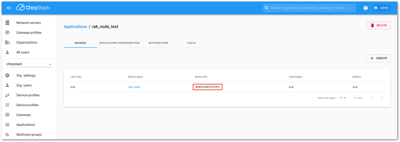 Figure 1: Chirpstack OTAA List of Device in the Device Tab
- To end the process, it is a good practice to review that the Application Key is properly associated with this device. The Application Key can be verified in the KEYS(OTAA) tab, as shown in Figure 46.
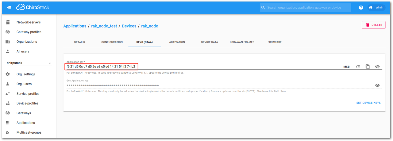 Figure 1: Application Key Associated with the New Device
Standard OTAA mode requires the Device EUI, Application Key, and the Application EUI. However, in ChirpStack’s implementation, only the Device EUI and Application Key are mandatory; the Application EUI is not required or recorded in the Application tab. Despite this, the Application EUI is a mandatory parameter in the RAK4270 Breakout Board firmware. To resolve this mismatch, you can reuse the Device EUI as the Application EUI when configuring the node.
Configure the OTAA mode on the RAK4270 Breakout Board
The RAK4270 Breakout Board supports a series of AT commands to configure its internal parameters and control the functionalities of the module.
To set up the RAK4270 Breakout to join ChirpStack using OTAA, start by connecting the board to the computer (see Figure 2) and open the RAK Serial Port Tool. Wait for the communication to start. It is recommended to test the serial communication by sending either of these two AT commands:
at+get_config=lora:status
at+version
As an example, these are the list of the parameters you need to configure in the RAK4270 Breakout Board:
- LoRa join mode: OTAA
- LoRa class: Class A
- LoRa region: EU868
- Device EUI: 5e9d1e0857cf25f1
- Application EUI: 5e9d1e0857cf25f1
- Application Key: f921d50cd7d02ee3c5e6142154f274b2
- Set the LoRa join mode to OTAA.
at+set_config=lora:join_mode:0
- Set the LoRa class to Class A.
at+set_config=lora:class:0
- Set the frequency/region to EU868.
- Refer to the RAK4270 Breakout Board Datasheet for the list of supported frequencies.
at+set_config=lora:region:EU868
- Set the Device EUI.
at+set_config=lora:dev_eui:5e9d1e0857cf25f1
- Set the Application EUI.
at+set_config=lora:app_eui:5e9d1e0857cf25f1
The App EUI parameter is not needed for the ChirpStack platform; therefore, you will use the same ID as the Device EUI. Otherwise, the firmware will fail to connect to the network server.
- Set the Application Key.
- Get the Application Key from the TTN register.
at+set_config=lora:app_key:f921d50cd7d02ee3c5e6142154f274b2
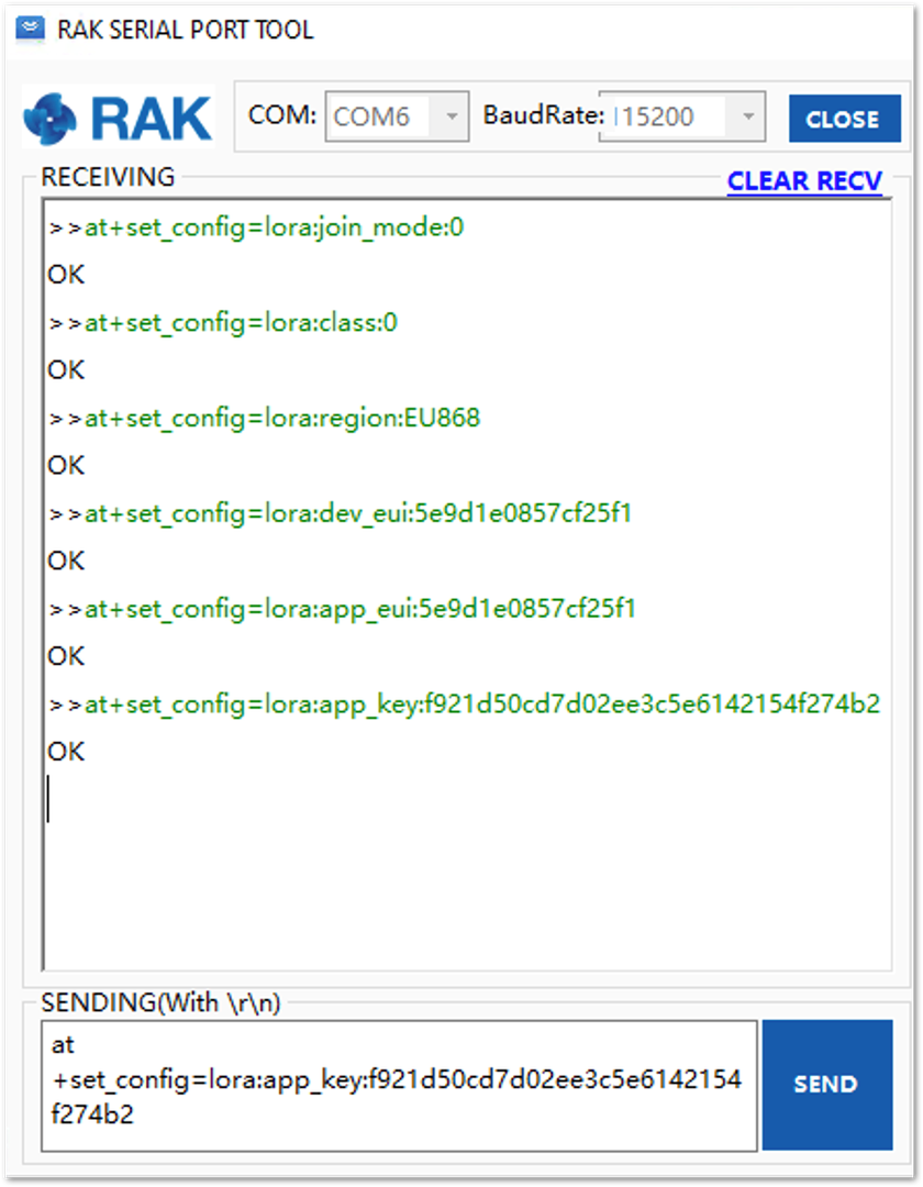 Figure 1: Chirpstack OTAA configuration via RAK Serial Port Tool
After configuring all the parameters, reset your RAK4270 Breakout Board to save the parameters.
- Join the Network.
at+join
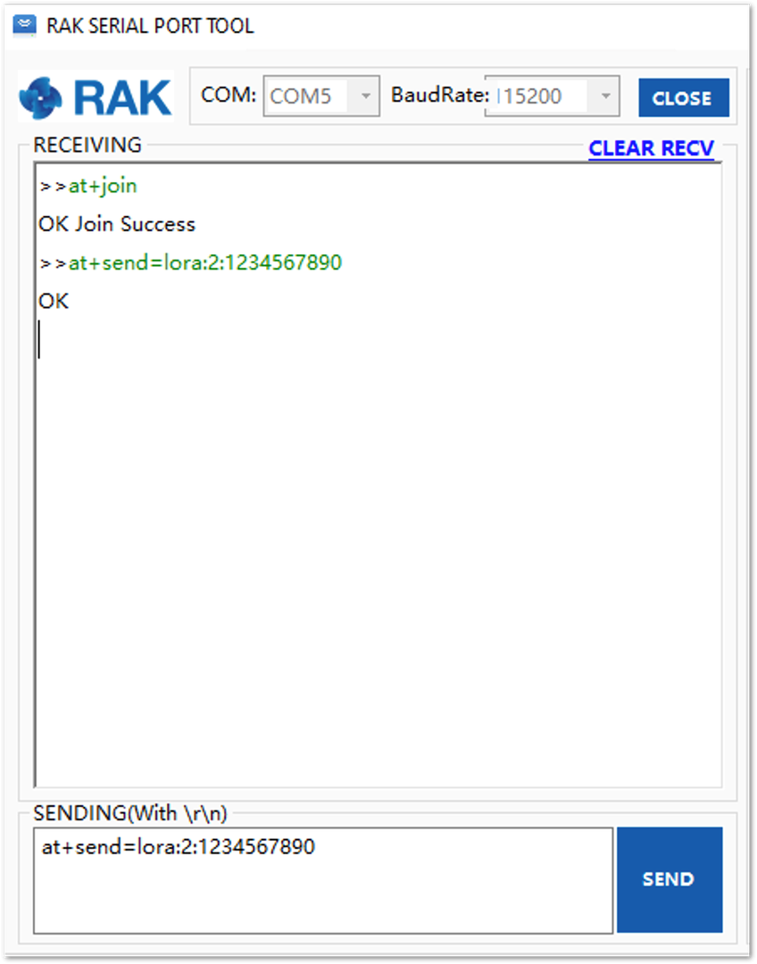 Figure 1: Chirpstack OTAA Join the Network via RAK Serial Port Tool
- You will see the JoinRequest and JoinAccept on the ChirpStack page.
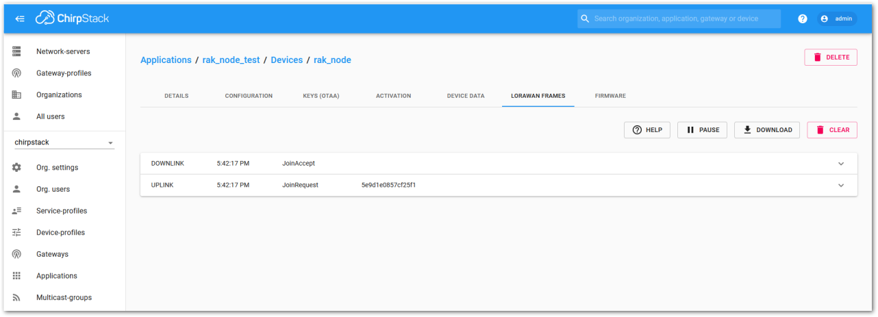 Figure 1: Check LoRaWAN Joint Request in Chirpstack OTAA Console
- Try to send data from the RAK4270 Breakout Board to ChirpStack.
at+send=lora:2:1234567890
 Figure 1: Send a LoRaWAN Message via RAK Serial Port Tool
On the ChirpStack platform, you can view messages in the LORAWAN FRAMES tab, as shown in Figure 52. By convention:
- Messages sent from nodes to gateways are referred to as Uplinks.
- Messages sent from gateways to nodes are referred to as Downlinks.
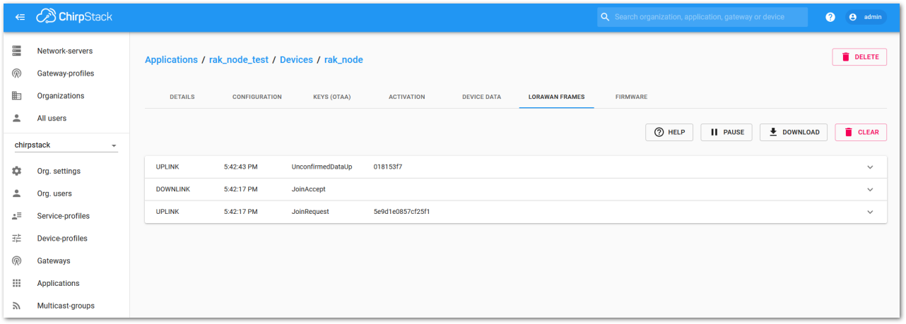 Figure 1: Chirpstack Data Received Preview
This concludes the exercise to send data in the OTAA mode.
ABP Mode
Configure the ABP Mode on the Platform
When registering a new device, if you select DeviceProfile_ABP, as shown in Figure 53, the ChirpStack platform will assume that the device will connect to the LoRaWAN network using ABP mode.
Enable the Disable frame counting verification option. During testing, restarting the module resets the frame counter to zero, which can cause a synchronization issue with the ChirpStack server, interpreting it as a replay attack. Disabling this feature is safe for testing purposes, but ensure it is reactivated in a production environment.
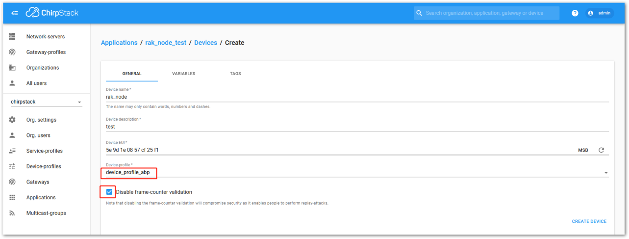 Figure 1: ChirpStack Console, Configuring a Device
After selecting the ABP mode, the following parameters appear in the Activation tab:
- Device address
- Network Session Key
- Application Session Key
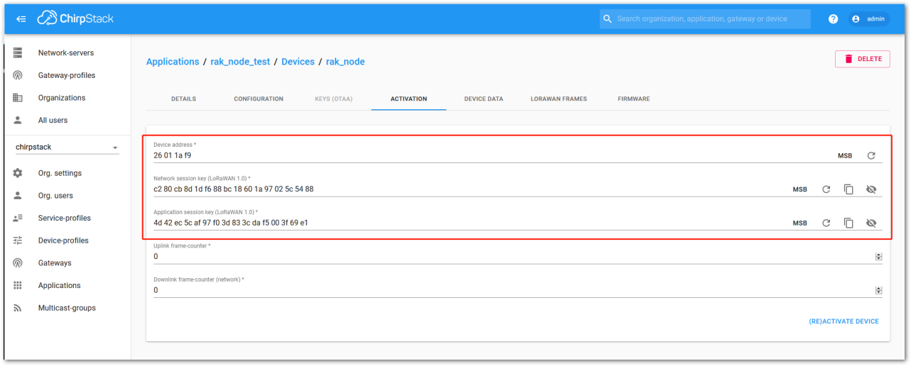 Figure 1: Chirpstack ABP Activation Parameters Needed
- The parameters can be either randomly generated by the platform or manually set with user-defined values. Once all parameters are correctly filled in, complete the process by clicking the ACTIVATE DEVICE button.
Configure the ABP Mode on the RAK4270 Breakout Board
In the following steps, you will configure the RAK4270 Breakout Board to work in the ABP mode. To set up the RAK4270 Breakout Board to join ChirpStack using ABP, start by connecting the board to the computer (see Figure 2) and open the RAK Serial Port Tool. Wait for the communication to start. It is recommended to test the serial communication by sending either of these two AT commands:
at+get_config=lora:status
at+version
As an example, these are the list of the parameters you need to configure in the RAK4270 Breakout Board:
- LoRa join mode: ABP
- LoRa class: Class A
- LoRa region: EU868
- Device address: 26011af9
- Network Session Key: c280cb8d1df688bc18601a97025c5488
- Application Session Key: 4d42ec5caf97f03d833cdaf5003f69e1
- Set LoRa join mode to ABP.
at+set_config=lora:join_mode:1
- Set LoRa class to Class A.
at+set_config=lora:class:0
- Set the frequency/region to EU868.
- Refer to the RAK4270 Breakout Board Datasheet for the list of supported frequencies.
at+set_config=lora:region:EU868
- Set the Device Address.
at+set_config=lora:dev_addr:26011af9
- Set the Network Session Key.
at+set_config=lora:nwks_key:c280cb8d1df688bc18601a97025c5488
- Set the Application Session Key.
at+set_config=lora:apps_key:4d42ec5caf97f03d833cdaf5003f69e1
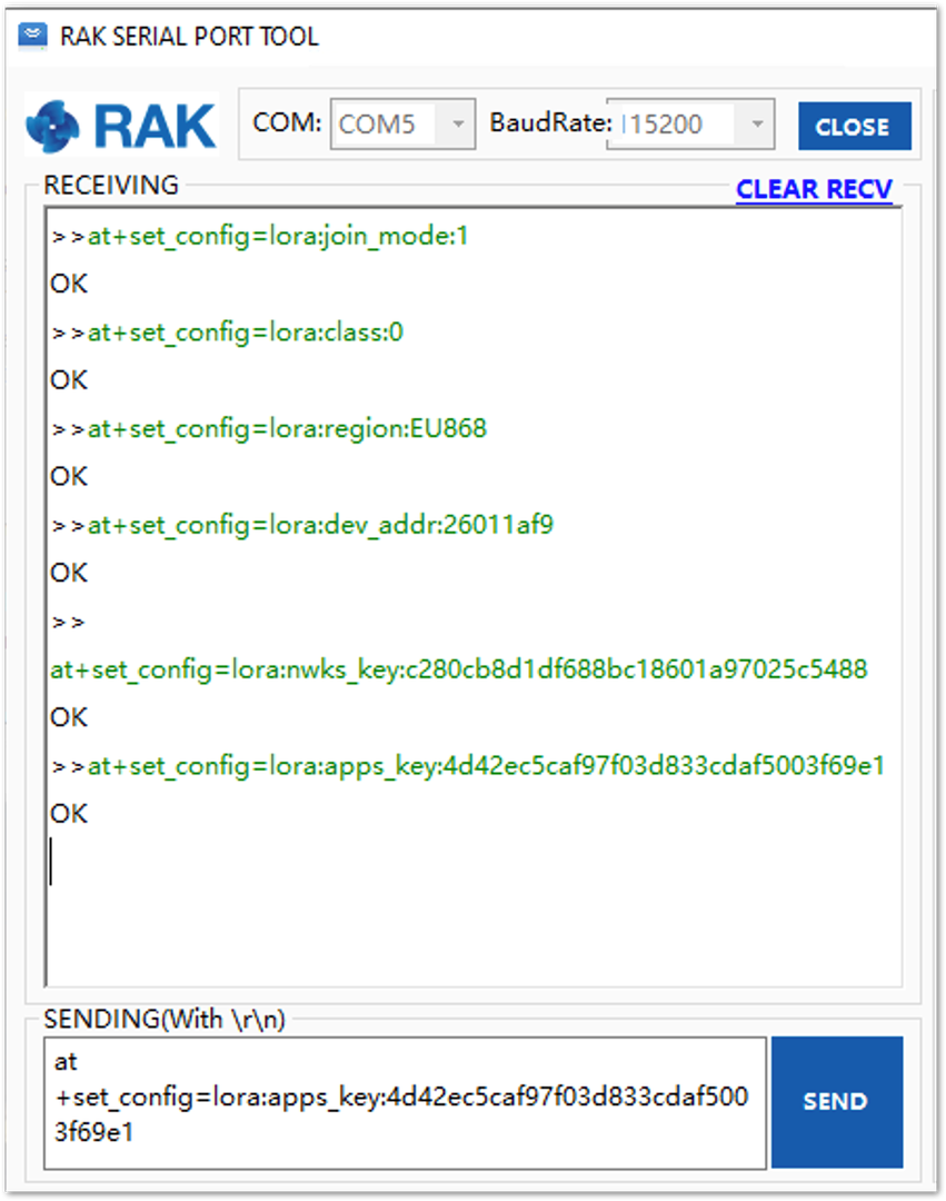 Figure 1: Chirpstack ABP Parameters Configuration via RAK Serial Port Tool
After configuring all the parameters, reset your RAK4270 Breakout Board to save the parameters.
- Join in ABP mode.
at+join
In ABP mode, the LoRaWAN protocol does not require the device to join a network before sending a LoRaWAN packet. However, to maintain the consistency of the internal states in the RAK4270 Breakout Board firmware, the at+join command must still be sent. The firmware will respond almost immediately with OK.
- Try to send data from the RAK4270 Breakout Board to ChirpStack.
at+send=lora:2:1234567890
 Figure 1: Chirpstack Sample Data Sent via RAK Serial Port Tool
LoRa P2P Mode
This section explains how to set up and connect two RAK4270 Breakout Board units to operate in LoRa P2P mode using EU868 as the frequency. The steps are also applicable to other standard frequency bands. To begin this process, ensure you have the following requirements:
-
Both RAK4270 Breakout Board units must be configured to operate on the EU868 frequency.
-
The setup of the RAK4270 Breakout Board units involves connecting them to a general-purpose computer via the UART port. Each board can be configured separately, but testing the LoRa P2P mode requires both units to be connected simultaneously to their respective UART ports. This setup can be achieved using:
- One computer with two available USB ports, or
- Two computers, each with one available USB port.
- Set the RAK4270 Breakout Board to work in LoRa P2P mode. Open the RAK Serial Port Tool and send the following command:
at+set_config=lora:work_mode:1
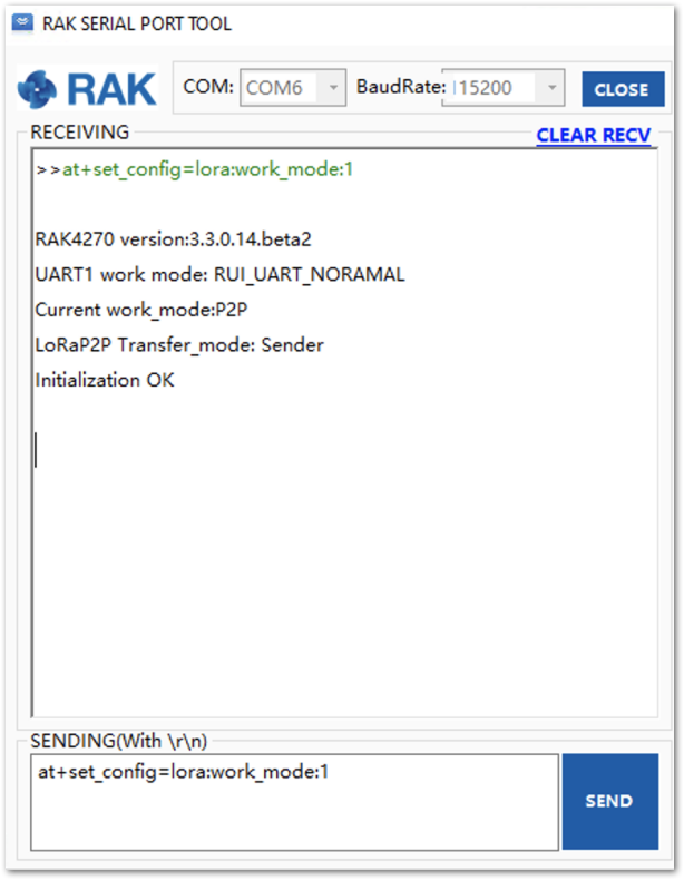 Figure 1: P2P Initialization
- Configure LoRa P2P parameters for both of them.
at+set_config=lorap2p:XXX:Y:Z:A:B:C
For this example, the LoRa parameters are the following:
- Link frequency: 869525000 Hz
- Spreading factor: 7
- Bandwidth: 125 kHz
- Coding Rate: 4/5
- Preamble Length: 5
- Power: 5 dBm
Refer to the Configuring Using AT Commands section to learn more about the definition of the parameters used.
Hence, it is translated into the following RAK4270 Breakout Board AT command and sent to both units.
at+set_config=lorap2p:869525000:7:0:1:5:5
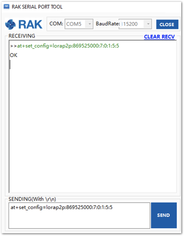 Figure 1: Configure P2P in both RAK4270 Breakout Board
- Set the transmission mode of the module. Unit 1 is configured as the sender, and Unit 2 is set to the receiver by AT command.
at+set_config=lorap2p:transfer_mode:2
at+set_config=lorap2p:transfer_mode:1
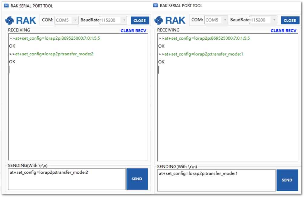 Figure 1: Set Modes in both RAK4270 Breakout Board
- Try to send a message from Unit 1 to Unit 2.
at+send=lorap2p:1234567890
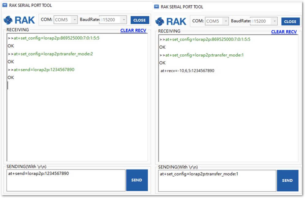 Figure 1: Message sent and received status in the two modules
Miscellaneous
Upgrade the Firmware
Before you start working with the RAK4270 Breakout Board, it is recommended to keep the board updated to the latest version of the firmware. Download the latest RAK4270 firmware.
For RAK4270 modules with firmware version V3.0.0.12 or below, use the STM32CubeProgrammer to upgrade the firmware. Upload the .hex file (not the .bin file) of the latest RAK4270 firmware. Older firmware versions have a different bootloader code and are incompatible with the RAK DFU Tool.
In the following sections, two (2) options for flashing new firmware in the RAK4270 Breakout Module are shown: Upgrade through DAPLink and Upgrade through UART1.
Firmware Upgrade Through DAPLink
Refer to the RAKDAP1 Flash and Debug Tool guide in the Accessories Category.
Firmware Upgrade Through UART1
Minimum Hardware and Software Requirements
Refer to the table for the minimum hardware and software required to perform the firmware upgrade using J-Link.
| Hardware/Software | Requirement |
|---|---|
| Computer | A Windows/Ubuntu/Mac computer |
| Firmware File | Bin firmware file downloaded from the website |
| Others | A USB to TTL module |
Firmware Upgrade Procedure
Execute the following procedure to upgrade the firmware in Device Firmware Upgrade (DFU) mode through the UART1 interface.
-
Download the latest application firmware of the RAK4270 Breakout Board.
-
Download the RAK Device Firmware Upgrade (DFU) tool.
-
Connect the RAK4270 Breakout Board with a computer through a USB to TTL.
-
Open the Device Firmware Upgrade tool. Select the serial port and baud rate of the module and click the Select Port button.
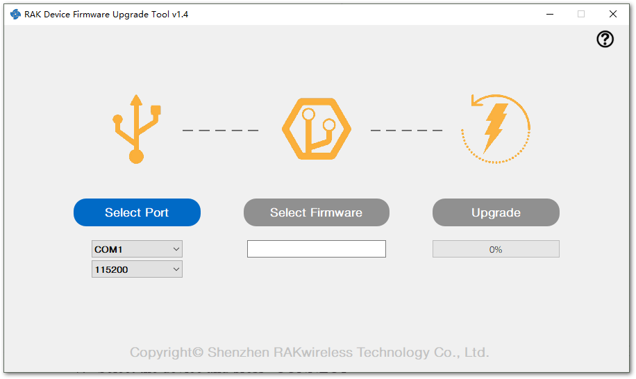 Figure 1: Device Firmware Upgrade Tool
- Select the application firmware file of the module with the suffix
.bin.
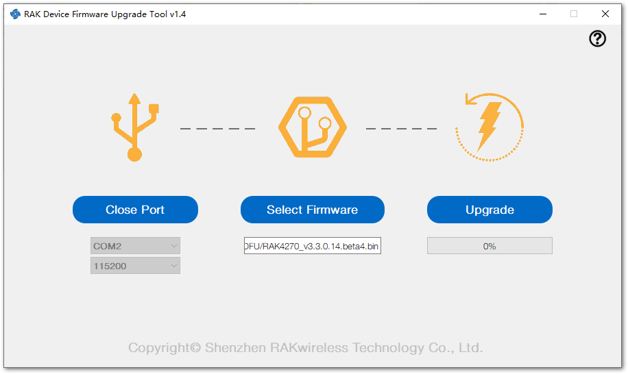 Figure 1: Select Firmware
- Click the Upgrade button to upgrade the device. After the upgrade is complete, the RAK4270 Breakout Board will be ready to work with the new firmware.
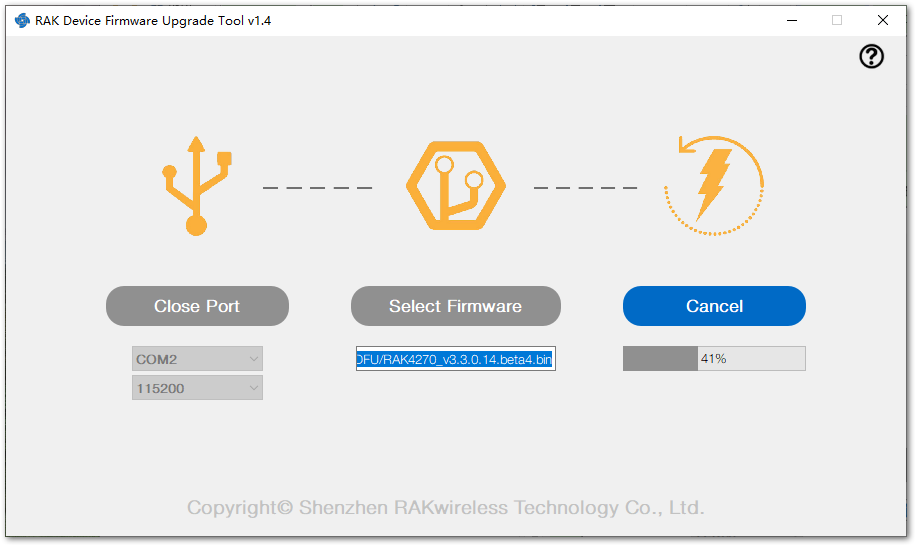 Figure 1: Firmware Upgrading
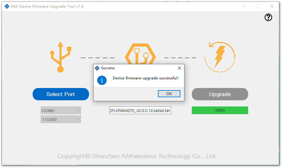 Figure 1: Upgrade Successful