RAK4630 WisDuo LoRaWAN+BLE Module Quick Start Guide
Prerequisites
Package Inclusion
Before going through the steps in the installation guide of the RAK4630 WisDuo LoRaWAN Module, make sure to prepare the necessary items listed below:
Hardware
- RAK4630 WisDuo LoRaWAN+BLE Module
- Computer
- USB to UART TTL adapter
Software
- Download and install the Arduino IDE.
If you are using Windows 10. Do NOT install the Arduino IDE from the Microsoft App Store. Install the original Arduino IDE from the Arduino official website! The Arduino app from the Microsoft App Store has problems using third-party Board Support Packages.
Product Configuration
RAK4630 as a Stand-Alone Device Using RUI3
Hardware Setup
Before you can start using the RAK4630, you need to make a few hardware connections. The bare minimum requirements include configuring the power section, connecting the reset button, antenna, and USB connection.
There are two ways to set up the RAK4630, depending on your power source. The following two modes are derived from the features of the nRF52840 chip embedded inside the RAK4630 module.
- High Voltage Mode: for an external battery and 3.3 V
- Normal Mode: for a 3.3 V voltage rail as a power source
1. Standard Mode
In standard mode, you can use 3.3V power source to all voltage supply input.
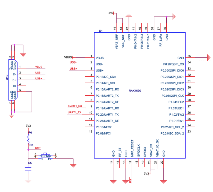 Figure 1: RAK4630 Standard Mode
2. High Voltage Mode
In high voltage mode, you can directly connect your external source (usually battery) to VBAT_NRF pin. VBAT_NRF should be higher than 3.3 V which is the nominal operating VDD level and must be left floating. The maximum allowed voltage for VBAT_NRF is 5.5 V.
This configuration is required in nRF52840 inside the RAK4630 to operate in High Voltage Mode in which internal DC/DC and REG0/REG1 are enabled. This is the default setting on the RAK4631 WisBlock Core which uses RAK4630 module.
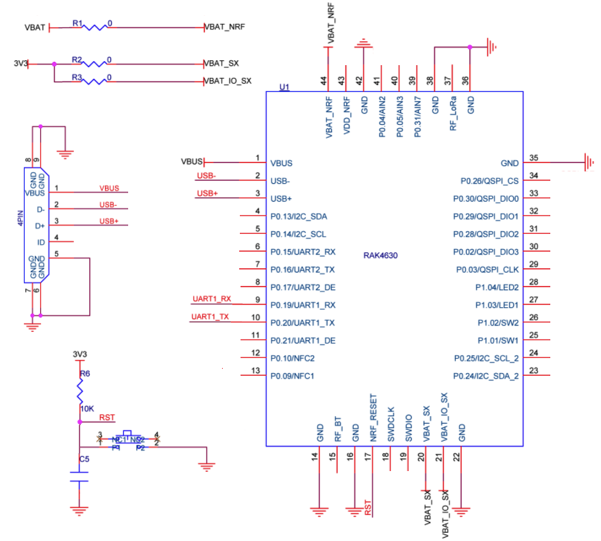 Figure 1: RAK4630 High Voltage Mode
After selecting appropriate mode for your applicaiton, ensure that the antennas are properly connected to have a good LoRa and BLE signal. Also, note that you can damage the RF section of the chip if you power the module without an antenna connected to the IPEX connectors.
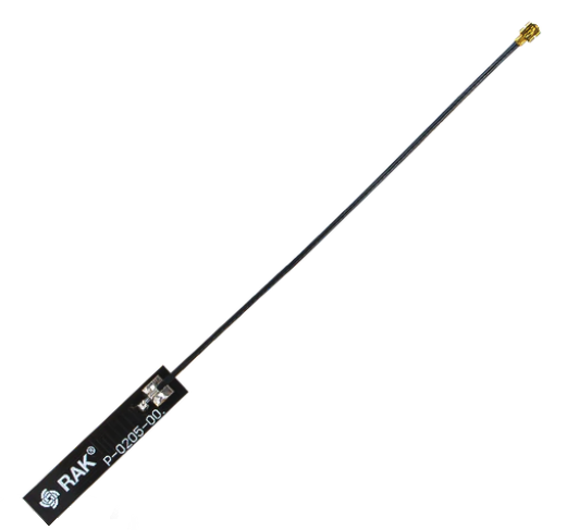 Figure 1: LoRa antenna
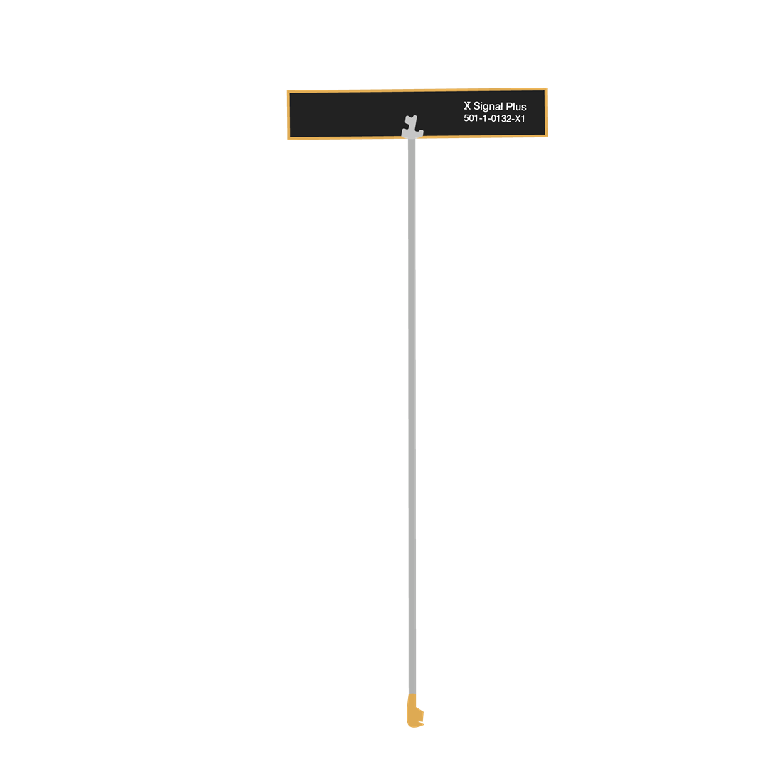 Figure 1: BLE antenna
RAK4630 has a label on its sticker on where to connect the antennas, as shown in Figure 4.
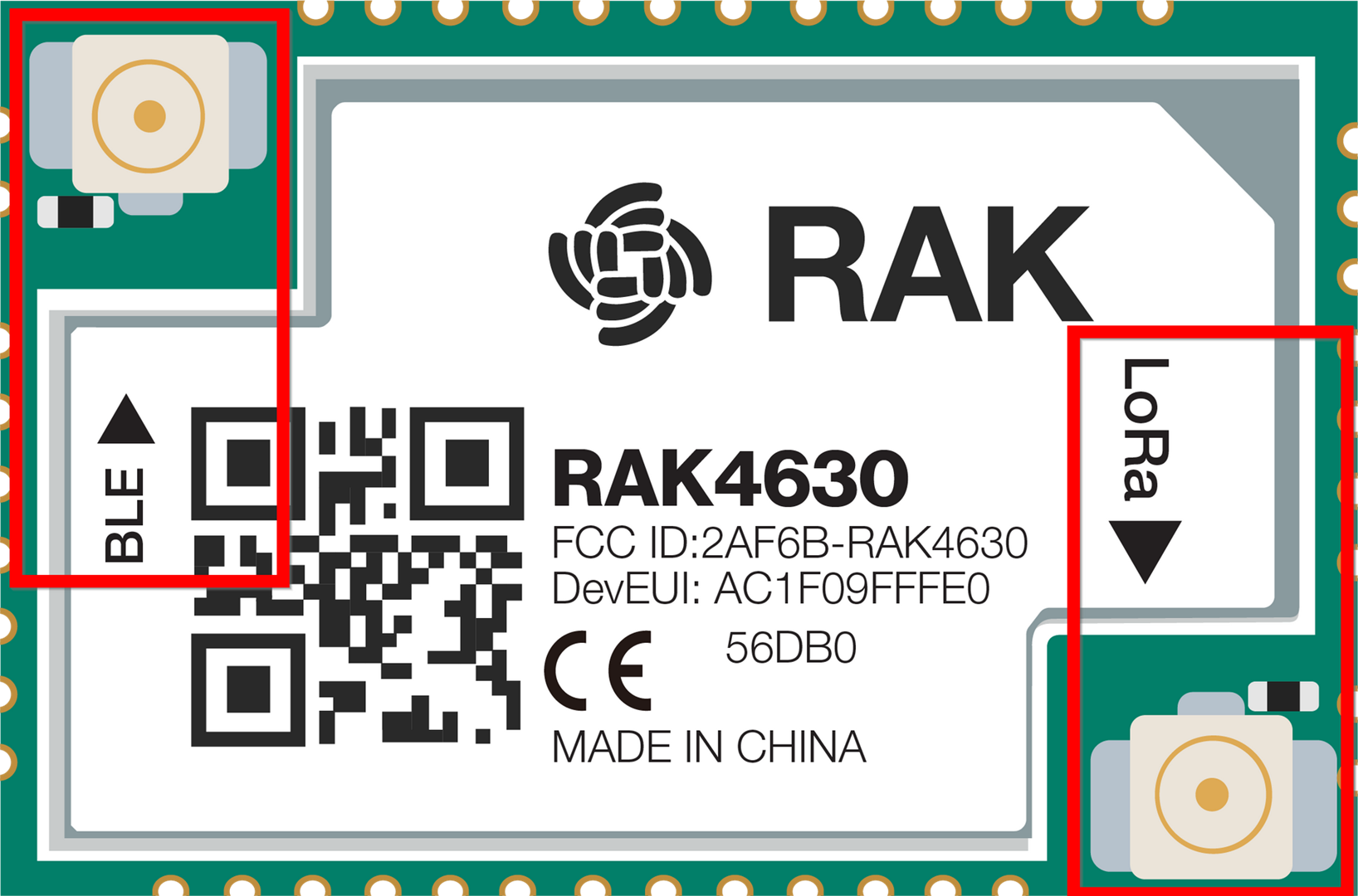 Figure 1: RAK4630 antenna label
Detailed information about the RAK4630 LoRa antenna can be found on the 863-870 MHz antenna datasheet or the 902-928 MHz antenna datasheet. For the BLE antenna, you can visit the 2.4 GHz Antenna specifications.
When using the LoRa or Bluetooth Low Energy transceivers, make sure that an antenna is always connected. Using these transceivers without an antenna can damage the module.
Software Setup
The default firmware of RAK4630 is based on RUI3, enabling you to develop your custom firmware to connect sensors and other peripherals. To develop your custom firmware using Arduino IDE, add first the RAKwireless RUI nRF Boards in the Arduino board manager, then you can utilize RUI3 APIs for your intended application.
You can upload the custom firmware via USB or DFU OTA. Even when compiling custom firmware via RUI3, the AT commands of RAK4630 remain available. You can send AT commands via a USB connection, UART1, or wirelessly via a BLE connection.
RAK4630 RUI3 Board Support Package in Arduino IDE
If you don't have an Arduino IDE yet, you can download it from the Arduino official website and follow the installation procedure on the miscellaneous section of this document.
For Windows 10 and up users: If your Arduino IDE is installed from the Microsoft App Store, you need to reinstall your Arduino IDE by getting it from the Arduino official website. The Arduino app from the Microsoft App Store has problems using third-party Board Support Packages.
Once the Arduino IDE has been installed successfully, configure the IDE to add the RAK4630 to its board selection by following these steps.
- Open Arduino IDE and go to File > Preferences.
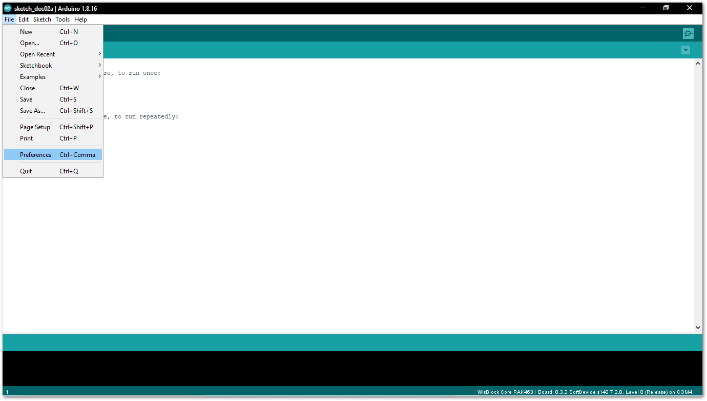 Figure 1: Arduino preferences
- To add the RAK4630 to your Arduino Boards list, edit the Additional Board Manager URLs. Click the icon, as shown in Figure 6.
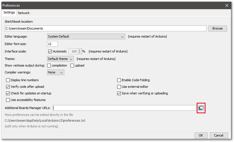 Figure 1: Modifying Additional Board Manager URLs
- Copy the URL
https://raw.githubusercontent.com/RAKWireless/RAKwireless-Arduino-BSP-Index/main/package_rakwireless_com_rui_index.jsonand paste it on the field, as shown in Figure 7. If other URLs are already there, just add them on the next line. After adding the URL, click OK.
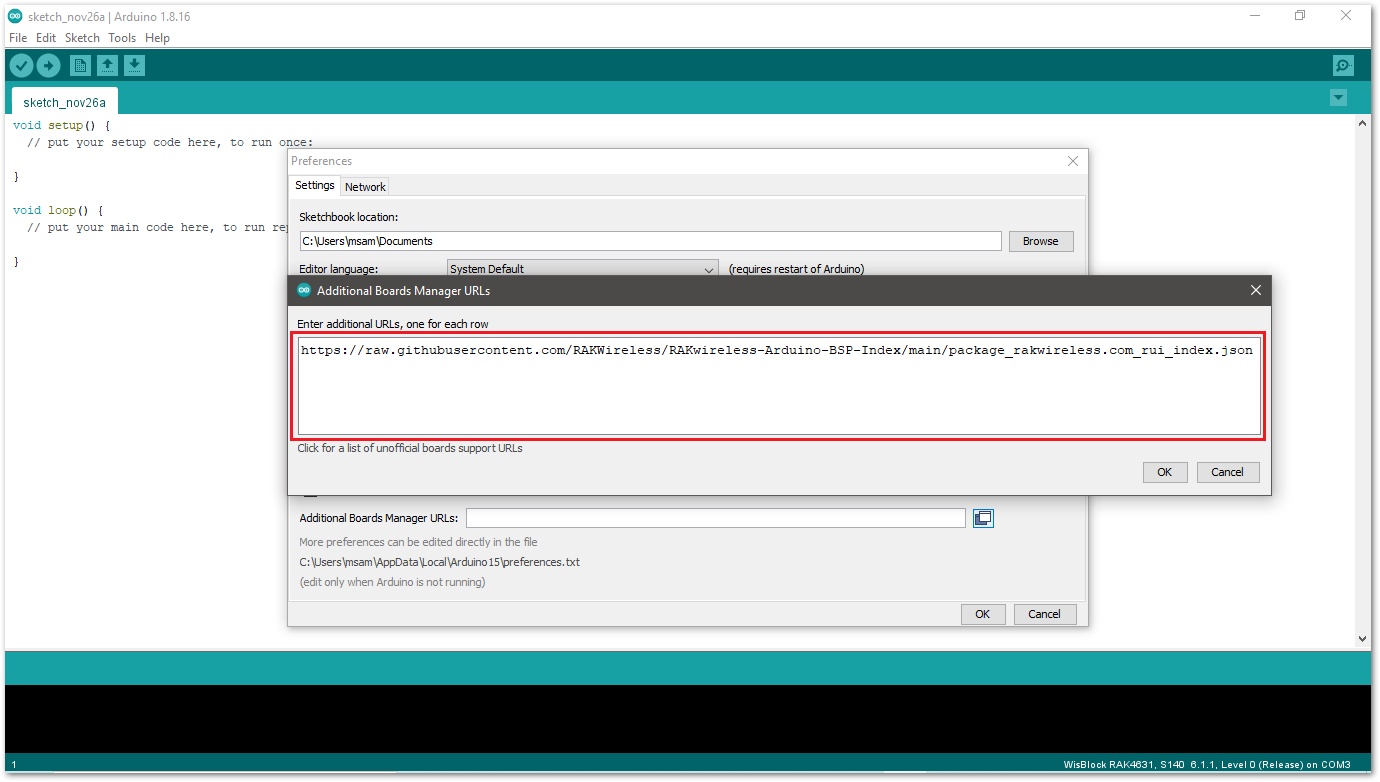 Figure 1: Add additional board manager URLs
- Restart the Arduino IDE.
- Open the Boards Manager from Tools Menu.
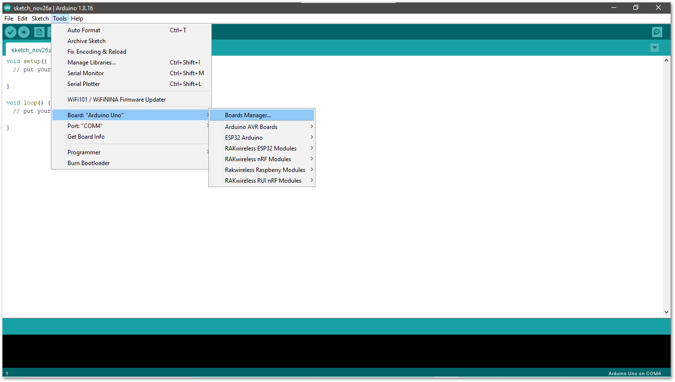 Figure 1: Opening Arduino boards manager
- Write
RAKin the search bar, as shown in Figure 9. This will show the available RAKwireless module boards that you can add to your Arduino Board list. Select and install the latest version of the RAKwireless RUI nRF Boards.
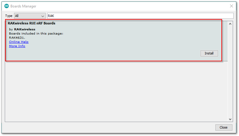 Figure 1: Installing RAKwireless RUI nRF boards
- Once the BSP is installed, select Tools > Boards Manager > RAKWireless RUI nRF Modules > WisBlock Core RAK4631 Board. The RAK4631 board uses the RAK4630 WisDuo module.
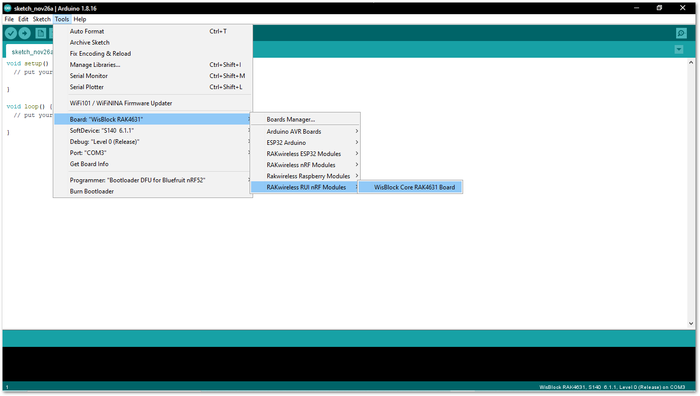 Figure 1: Selecting RAK4630 Module
Compile an Example with Arduino LED Breathing
- After completing the steps on adding your RAK4630 to the Arduino IDE, try to run a simple program to test your setup. You need to add two LEDs to the bare minimum schematic of the RAK4630 module, as shown in Figure 11.
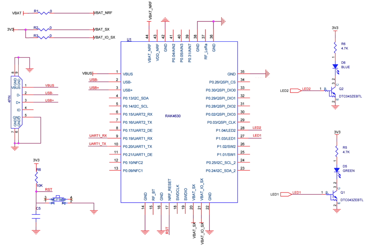 Figure 1: RAK4630 with two LEDs
VBAT should be higher than 3.3 V. The recommended value is the nominal voltage of a Li-Ion battery, which ranges from 3.7 V to 4.2 V. This is required because the power configuration of the nRF52840 inside the RAK4630 is High Voltage, DC/DC with REG0 and REG1 enabled.
- Connect the RAK4630 via USB and check RAK4630 COM Port using Windows Device Manager. Double-click the reset button if the module is not detected.
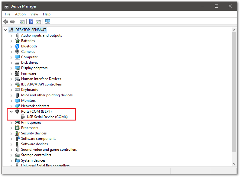 Figure 1: Device manager ports (COM & LPT)
- Choose RAK4631 on board selection select via Tools > Boards Manager > RAKWireless RUI nRF Modules > WisBlock Core RAK4631 Board.
 Figure 1: Selecting RAK4630 Module
- Open the Tools Menu and select a COM port. COM4 is currently used.
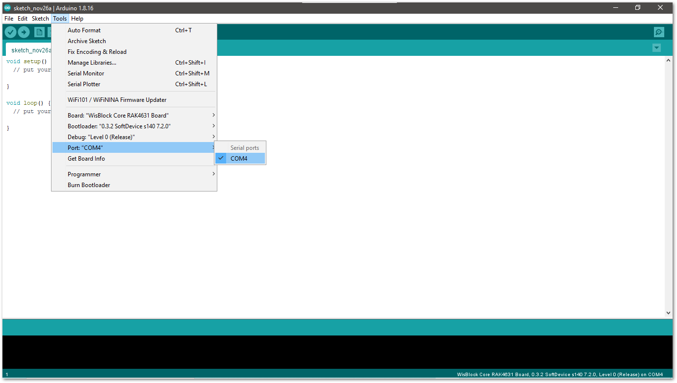 Figure 1: Select COM port
- Click the serial monitor icon to connect to the COM port.
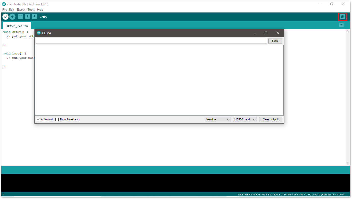 Figure 1: Open Arduino serial monitor
- If the connection is successful, you can send AT Commands to RAK4630. For example: To check the RUI version, type
AT+VER=?on the text area, then click on the Send button, as shown in Figure 16.
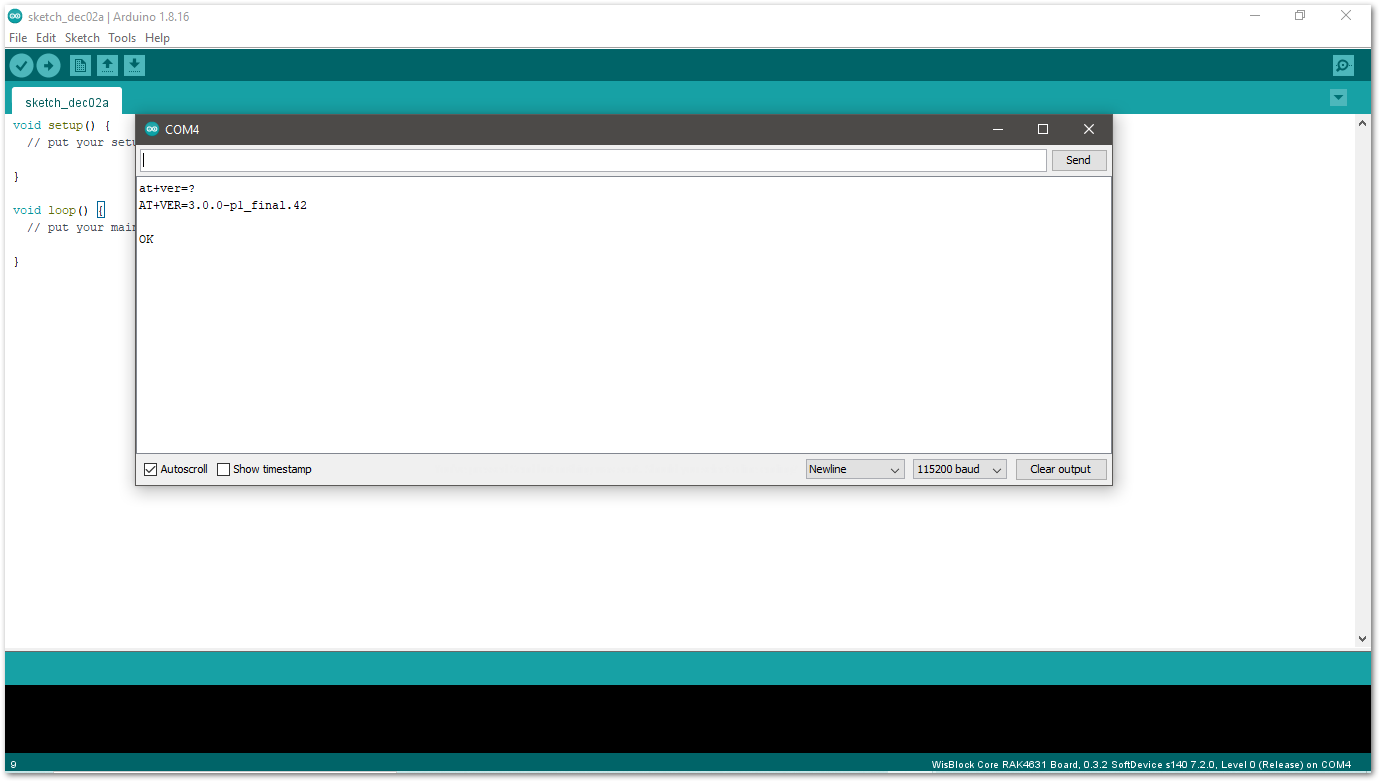 Figure 1: Arduino serial monitor COM4
- Open Arduino_Led_Breathing example code.
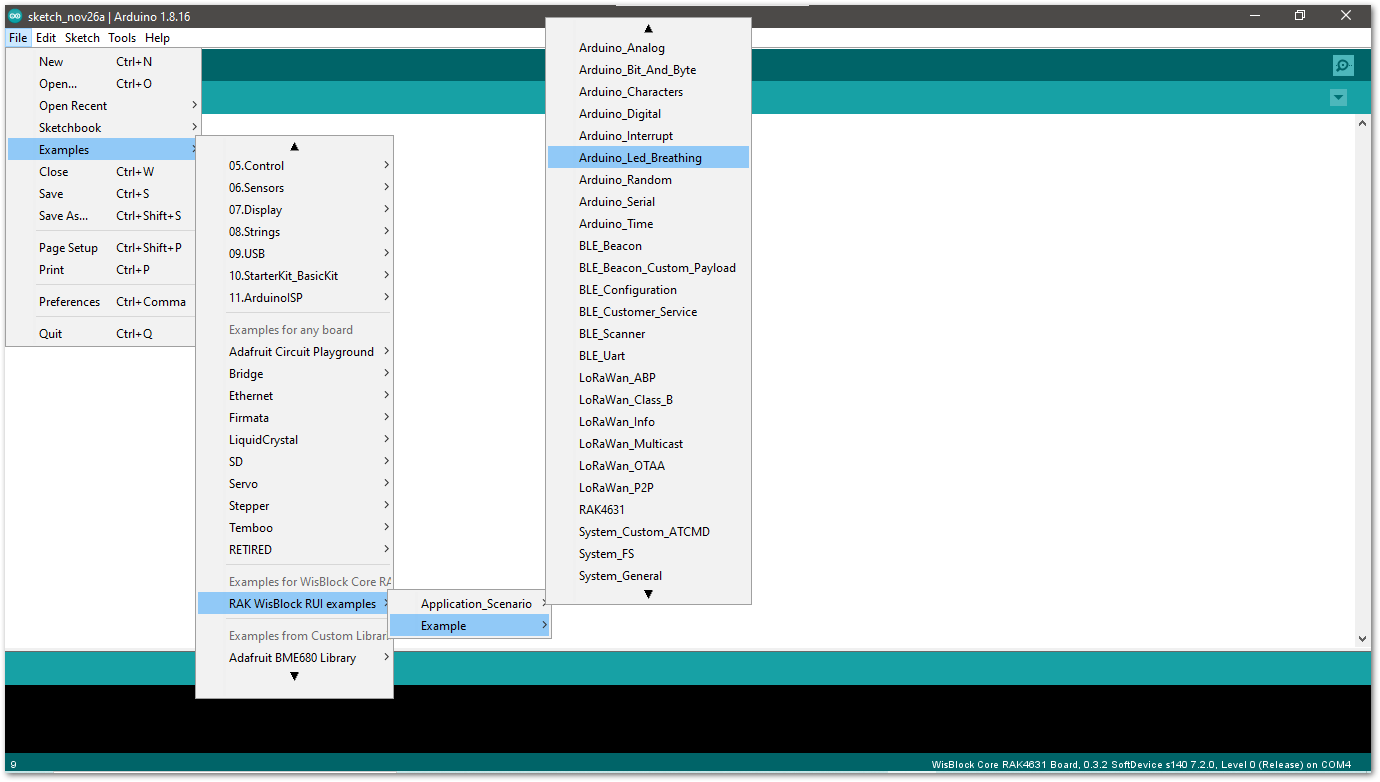 Figure 1: Led Breathing example
- Click on the Verify icon to check if you have successfully compiled the example code.
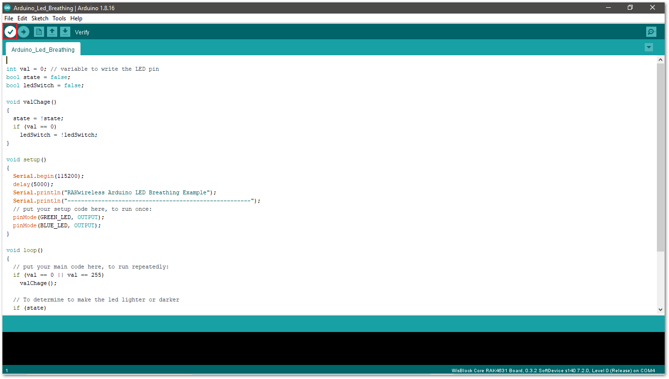 Figure 1: Verify the example code
- Click the Upload icon to send the compiled firmware to your RAK4630.
- RAK4630 should automatically go to BOOT mode when the firmware is uploaded via Arduino IDE.
- If BOOT mode is not initiated, you can manually send
AT+BOOTcommand to start bootloader mode.
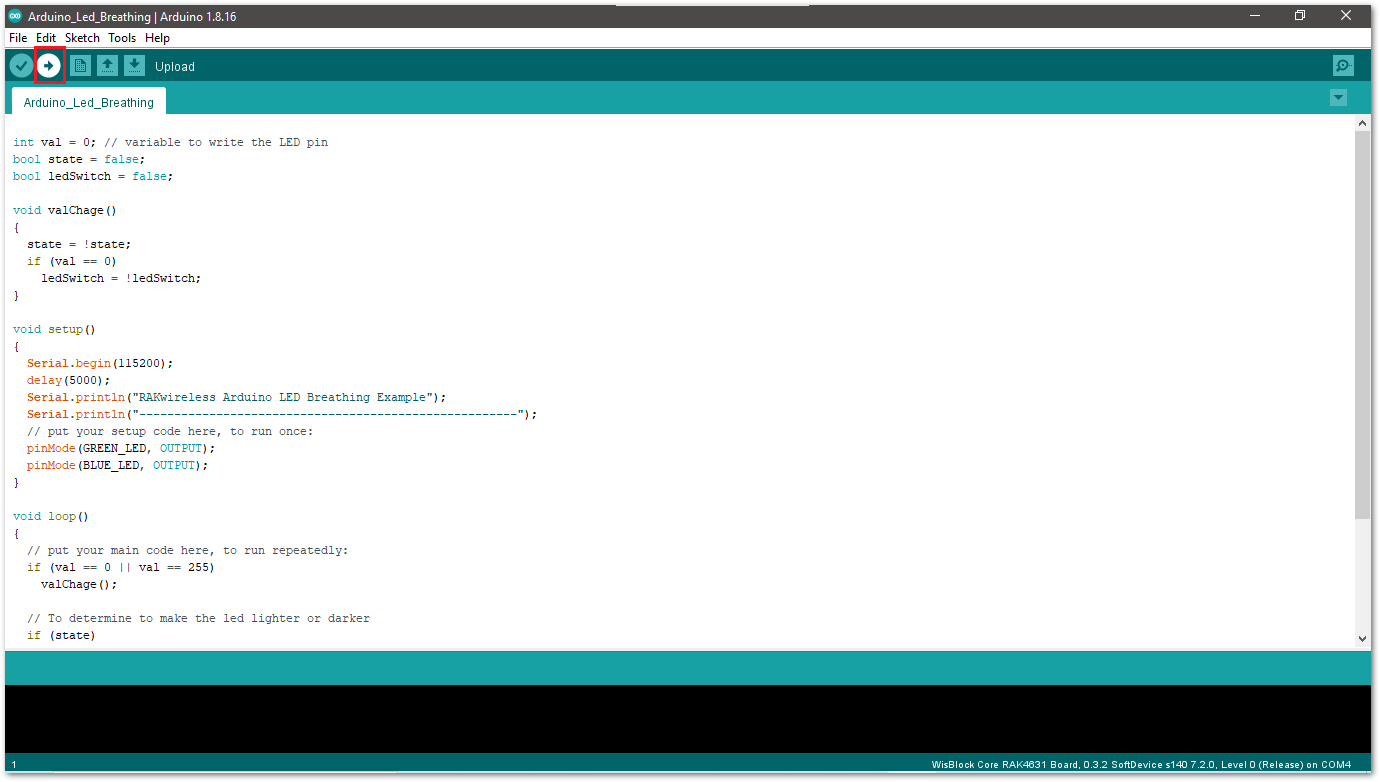 Figure 1: Upload the example code
- If the upload is successful, you will see the Device programmed message.
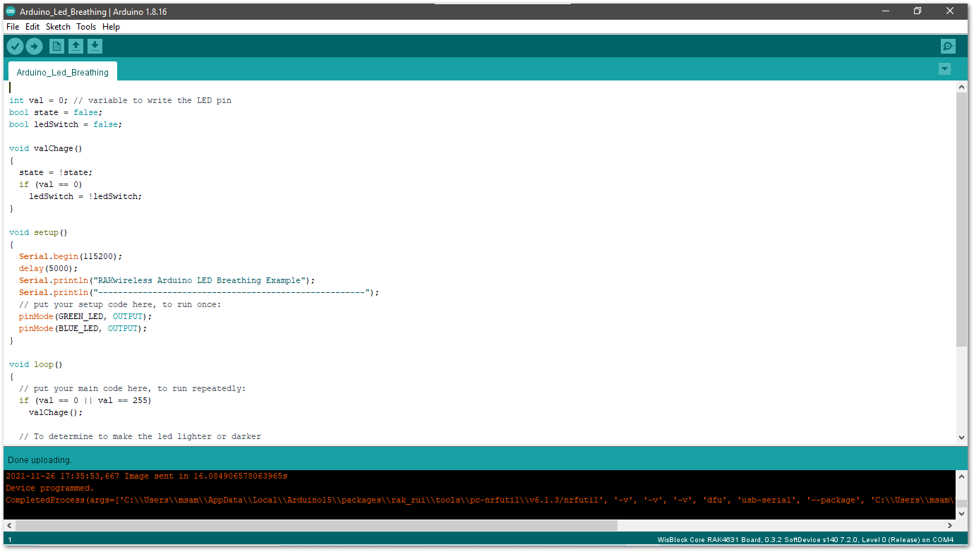 Figure 1: Device programmed successfully
- After the Device Programmed is completed, you will see that LEDs are blinking.
RAK4630 IO Pins and Peripherals
This section discusses how to use and access the pinouts of RAK4630 using RUI3 APIs. It shows basic code in using digital IO, analog input, UART, and I2C.
How to Use Digital IO
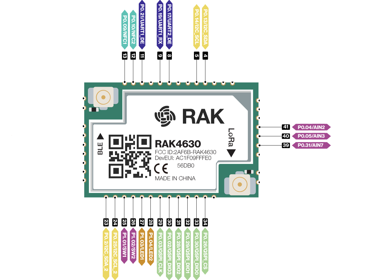 Figure 1: Available digital I/O pins in RAK4630
You can use any of the pins, as shown in Figure 22, as Digital Pin by replacing the dot . to underscore _. See the example code below.
/*
 RAK4631 Digital I/O Example

 You can use any of the following as Digital I/O:

 P0_03
 P0_04
 P0_05
 P0_09
 P0_10
 P0_13
 P0_14
 P0_17
 P0_19
 P0_21
 P0_24
 P0_25
 P0_26
 P0_28
 P0_29
 P0_30
 P0_31
 P1_01
 P1_02
 P1_03
 P1_04
*/

void setup()
{
  pinMode(P0_04, OUTPUT); //Change the P0_04 to any digital pin you want. Also, you can set this to INPUT or OUTPUT
}

void loop()
{
  digitalWrite(P0_04,HIGH); //Change the P0_04 to any digital pin you want. Also, you can set this to HIGH or LOW state.
  delay(1000); // delay for 1 second
  digitalWrite(P0_04,LOW); //Change the P0_04 to any digital pin you want. Also, you can set this to HIGH or LOW state.
  delay(1000); // delay for 1 second
}
How to Use Analog Input
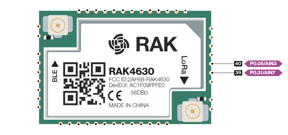 Figure 1: Available Analog Input pins in RAK4630
You can use any of the pins, as shown in Figure 23, as Analog Input Pin by replacing the dot . to underscore _. See the example code below.
#define analogPin P0_05  // or you can use P0_31

int val = 0;  // variable to store the value read

void setup()
{
  Serial.begin(115200);
}

void loop()
{
  val = analogRead(analogPin);  // read the input pin
  Serial.println(val);          // debug value
}
How to Use Serial Interfaces
- UART
There are two UART peripherals available on RAK4630. There are also different Serial Operating Modes possible in RUI3, namely Binary Mode, AT Mode, and Custom Mode.
| Serial Port | Serial Instance Assignment | Default Mode |
|---|---|---|
| UART1 (pin 19, 20) | Serial0 | AT Command |
| UART2 (pin 15, 16) | Serial1 | Custom Mode |
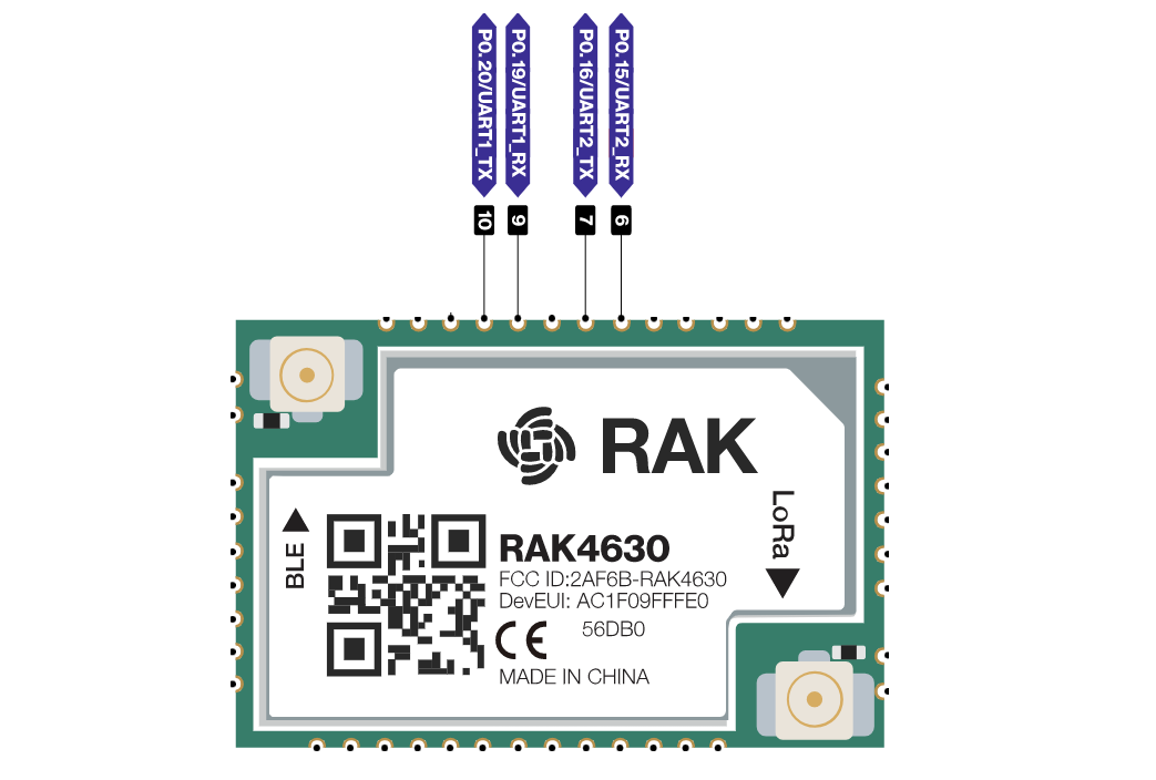 Figure 1: Available UART pins in RAK4630
Example Code
void setup()
{
  Serial0.begin(115200); //use Serial0 for UART1 and Serial1 for UART2 //you can designate separate baudrate for each.
}

void loop()
{
  Serial0.println("RAK4630 TEST!");
  delay(1000); // delay for 1 second
}
- I2C
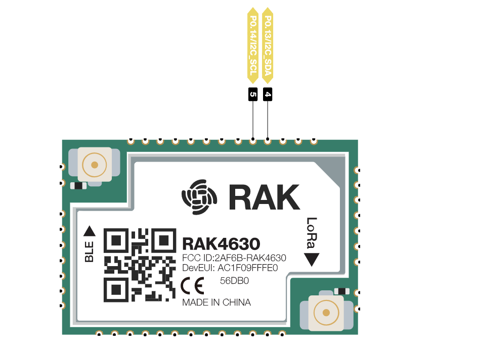 Figure 1: Available I2C pins in RAK4630
Make sure you have an I2C device connected to specified I2C pins to run the example code below.
#include <Wire.h>

void setup()
{
  Wire.begin();

  Serial.begin(115200);
  while (!Serial);
  Serial.println("\nI2C Scanner");
}

void loop()
{
  byte error, address;
  int nDevices;

  Serial.println("Scanning...");

  nDevices = 0;
  for(address = 1; address < 127; address++ )
  {
    // The i2c_scanner uses the return value of
    // the Write.endTransmisstion to see if
    // a device did acknowledge to the address.
    Wire.beginTransmission(address);
    error = Wire.endTransmission();

    if (error == 0)
    {
      Serial.print("I2C device found at address 0x");
      if (address<16)
        Serial.print("0");
      Serial.print(address,HEX);
      Serial.println("  !");

      nDevices++;
    }
    else if (error==4)
    {
      Serial.print("Unknown error at address 0x");
      if (address<16)
        Serial.print("0");
      Serial.println(address,HEX);
    }
  }
  if (nDevices == 0)
    Serial.println("No I2C devices found\n");
  else
    Serial.println("done\n");

  delay(5000);           // wait 5 seconds for next scan
}
- SPI
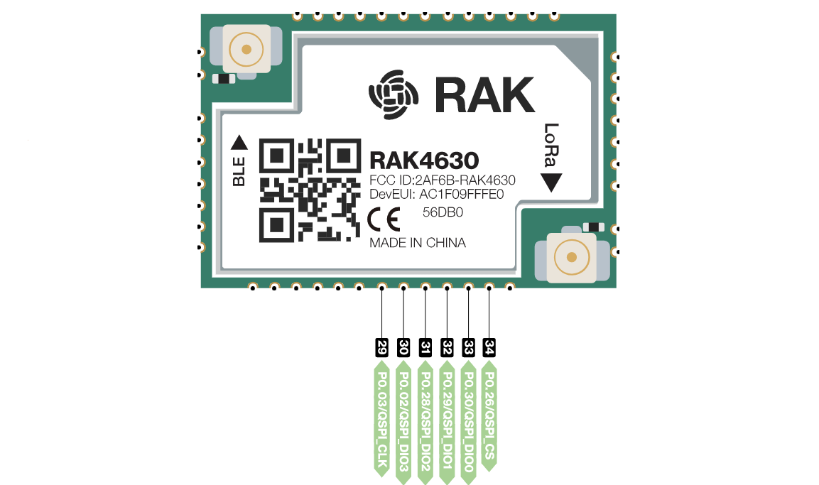 Figure 1: Available SPI pins in RAK4630
LoRaWAN Example
This example demonstrates how to program RAK4630 as a stand-alone LoRaWAN end-device using RUI3 Arduino APIs. To utilize RAK4630 as a LoRaWAN end-device, it must be in proximity to a functioning LoRaWAN gateway registered to a LoRaWAN network server (LNS) or with a built-in network server.
Additionally, this guide will utilize the internal network server of the WisGate Edge RAK7268LoRaWAN gateway. RAK provides a range of WisGate LoRaWAN gateways available for purchase from the RAK store. This guide concentrates on configuring RAK4630 as a LoRaWAN end-device.
As a refresher on LoRaWAN, here are the three main components you need for a functioning LoRaWAN application:
- LoRaWAN Gateway (this guide uses RAK7268 WisGate Edge gateway)
- LoRaWAN Network Server (this guide uses RAK7268 WisGate Edge built-in LoRaWAN network server)
- LoRaWAN End-Device (RAK4630 in this guide)
If you are new to LoRaWAN, here are a few good references about LoRaWAN and gateways:
- LoRaWAN 101
- What is a LoRaWAN Gateway
- How do LoRaWAN Gateways work?
- Things to Consider When Picking A LoRaWAN Gateway
LoRaWAN gateway models like WisGate Edge often come with built-in network servers. However, it's also common for LoRaWAN network servers to be external or in the cloud. One popular LoRaWAN network server in the cloud, which offers free usage with enterprise services available, is The Things Network (TTN).
Adding the RAK4630 as an End-Device to the LoRaWAN Network Server
- You need to have a functional RAK7268 to proceed with the next steps. For a complete guide, refer to RAK7268 WisGate Edge Quick Start Guide. Other WisGate Edge configurations can be found in the detailed documentation of the WisGate OS.
This section will guide you through adding a LoRaWAN application to the built-in network server of RAK7268 and adding a device to it. To perform these configurations, you'll need access to the RAK7268 console portal. The IP address you use to access the portal will depend on your type of connection to RAK7268. For instance, if your RAK7268 is configured as an Access Point, you can connect to it via http://192.168.230.1/.
This initial guide utilizes the LoRaWAN built-in network server of RAK7268, but you have the flexibility to use another LoRaWAN network server such as TTN, ChirpStack, Helium, AWS, etc. While these platforms may have different user interfaces, the parameters to be configured should remain the same as long as they adhere to the LoRaWAN specification standard.
- Once you have a functioning RAK7268 gateway, ensure that you are using the built-in LoRaWAN network server (LNS). You can configure this by selecting the LoRa Network tab and then choosing Network Settings.
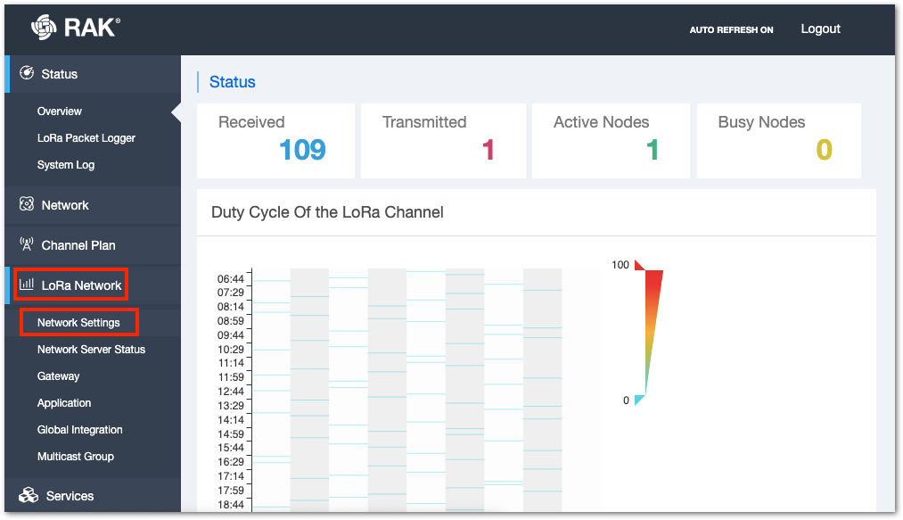 Figure 1: RAK7268 LoRa network settings
- Select the Mode dropdown list as Network Server and make sure to take note of the Region setting. The Region should match the region specified in the code for the RAK4630 that you will compile later in this guide. For instance, the region of the LoRaWAN gateway and LNS used in this guide is US915.
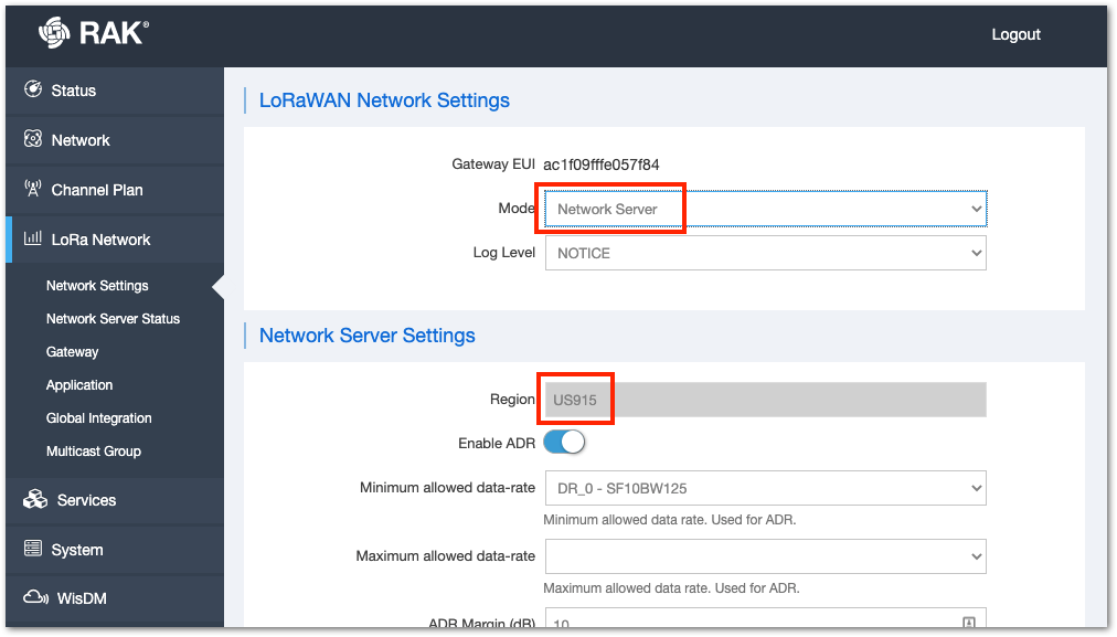 Figure 1: RAK7268 network server mode
- After configuring the gateway to use a built-in LoRaWAN network server (LNS), proceed to add an application to the network server and register a device. Click on Application, which will display all the LoRaWAN applications you currently have, if any.
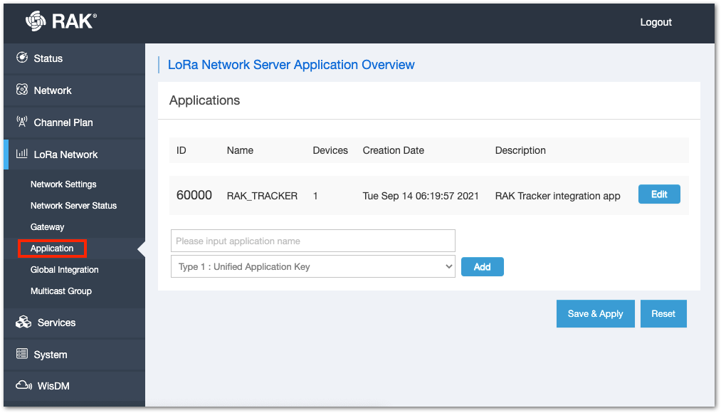 Figure 1: Accessing Application Console in the network server
- Ensure to assign a meaningful name to your application. For this illustration, RAK4630, select Unified Application Key, then click Add. After the configuration, click Save & Apply to proceed with the application's setup.
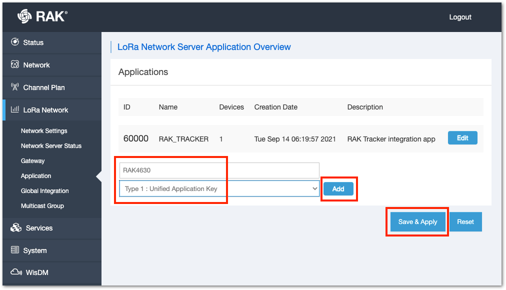 Figure 1: Adding Application to the LoRaWAN network server
- Another essential parameter in a LoRaWAN application is the Application Key, utilized in OTAA activation. While you can manually add one, it's advisable to let the network server generate it by clicking the generate icon button. Additionally, you can add a description to your application. Once you have the Application Key, click Save & Apply.
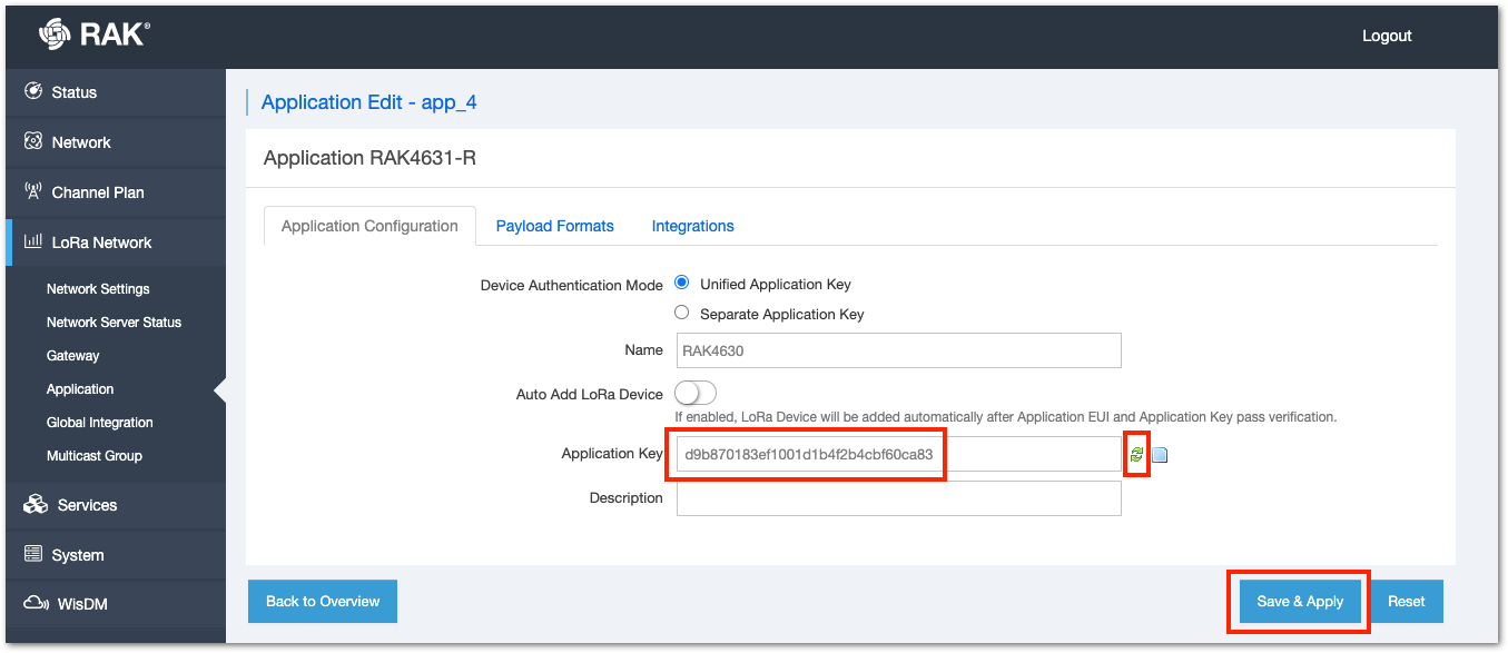 Figure 1: Configure Application Key
- The new application will now be added to the application list of your network server. To register the RAK4630 WisDuo module as a device in that application, click edit to access the application console.
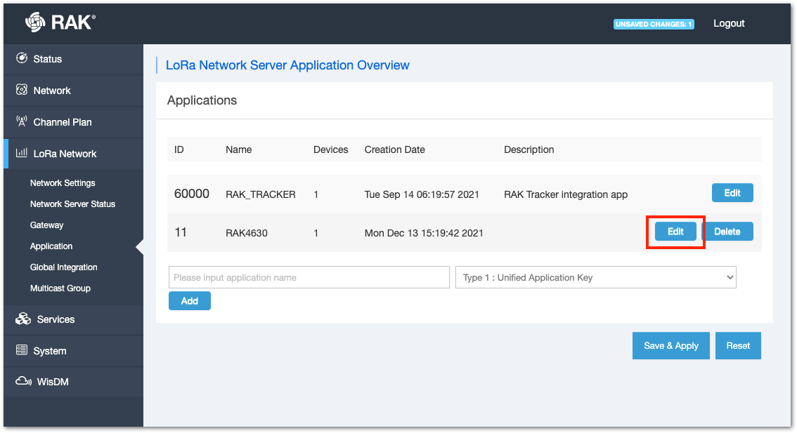 Figure 1: Access the LoRaWAN Application Console
- Add the device EUI (DEVEUI) on the application console. This must be unique, and it is highly encouraged that you use the DEVEUI printed on the sticker of your RAK4630 module. Then click the Add button to proceed with the next configurations.
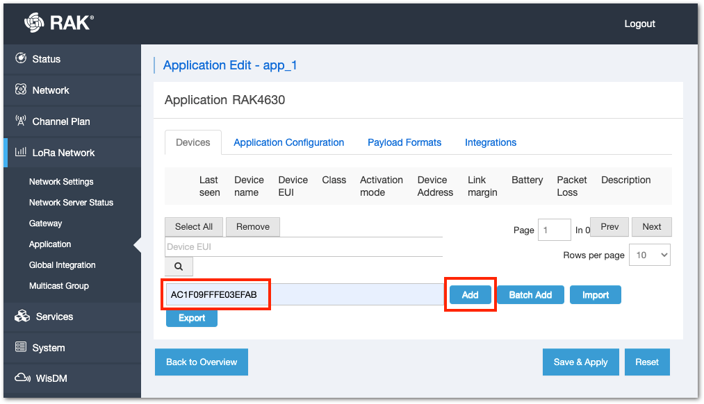 Figure 1: Adding device to the application
- Put a name on your device, in this case, RAK4630. Three parameters in this list must be the same as your RAK4630 code: Class, Join Mode, and Application Key.
In the Arduino code example in the latter part of this guide, Class A and Join Mode OTAA are the default. With that, you will only need to modify the code of the application key. Lastly, the LoRaWAN MAC Version must be 1.0.3. After setting up all these parameters, click Save & Apply.
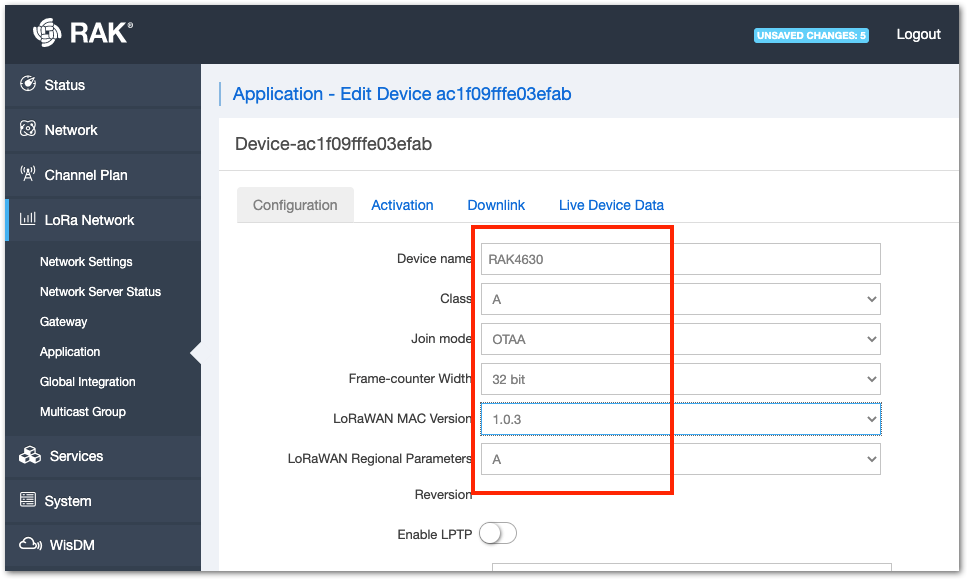 Figure 1: Configuration of the RAK4630 as OTAA device
- The device will now be shown as a device in your application. The next step is to prepare the RAK4630 WisDuo module so that it can match all the parameters in the network server.
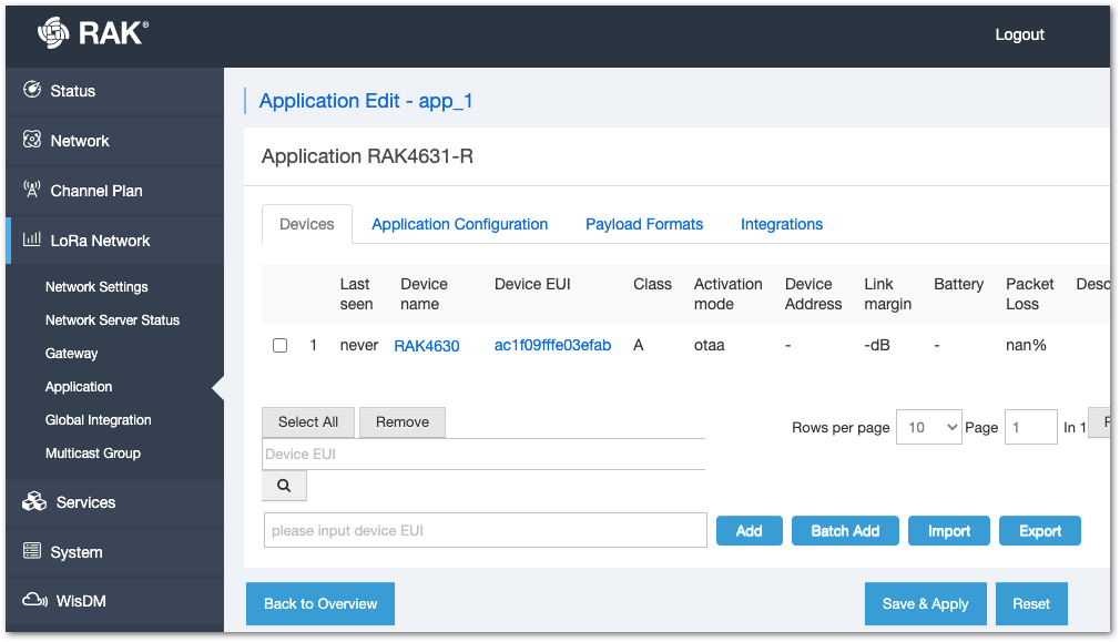 Figure 1: RAK4630 registered on the network server
Uploading LoRaWAN Example to RAK4630
After successfully registering the RAK4630 device to the LoRaWAN Network Server, you can proceed with running the LoRaWAN OTAA demo application example.
- Open the example code under RAK WisBlock RUI examples.
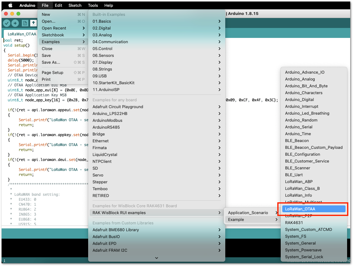 Figure 1: OTAA LoRaWAN application example
- In the example code, modify the device EUI (DEVEUI) and application key (APPKEY).
- The device EUI (DEVEUI) should match the device EUI registered in your network server. This is the same used in the previous section device registration in the network server. DEVEUI is MSB.
  // OTAA Device EUI MSB
  uint8_t node_device_eui[8] = {0xAC, 0x1F, 0x09, 0xFF, 0xFE, 0x03, 0xEF, 0xAB};
- Another important parameter to change is the application key (APPKEY). This parameter should also be the same as the APPKEY in the network server you configured in the previous section adding RAK4630 in the network server section. APPKEY is MSB.
// OTAA Application Key MSB
  uint8_t node_app_key[16] = {0xD9, 0xB8, 0x70, 0x18, 0x3E, 0xF1, 0x00, 0x1D, 0x1B, 0x4F, 0x2B, 0x4C, 0xBF, 0x60, 0xCA, 0x83};
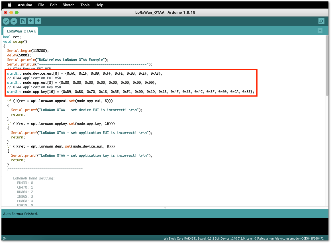 Figure 1: Updating DEVEUI and APPKEY
- This guide uses US915 regional band, so you need to update the band in the code as well. Additionally, set up the channel mask (channels 8 to 15 are the most commonly used channels in the US915 band).
  if(!(ret = api.lorawan.band.set(5)))
  {
       Serial.printf("LoRaWan OTAA - set band is incorrect! \r\n");
       return;
  }

  uint16_t maskBuff = 0x0002;
  api.lorawan.mask.set(&maskBuff);
RAK4630 supports the following regions:
- RAK_REGION_EU433 = 0
- RAK_REGION_CN470 = 1
- RAK_REGION_RU864 = 2
- RAK_REGION_IN865 = 3
- RAK_REGION_EU868 = 4
- RAK_REGION_US915 = 5
- RAK_REGION_AU915 = 6
- RAK_REGION_KR920 = 7
- RAK_REGION_AS923 = 8
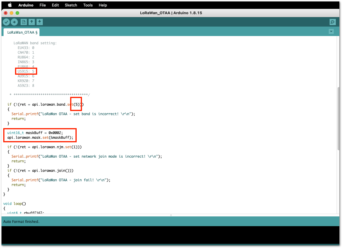 Figure 1: Updating to US915 and setting up channel mask
- The last step is to upload the code by clicking the Upload icon. Take note that you should select the right board and port, as shown in the previous example LED Blinking.
RAK4630 should automatically go to BOOT mode when the firmware is uploaded via Arduino IDE.
If BOOT mode is not initiated, you can manually send AT+BOOT command to start bootloader mode.
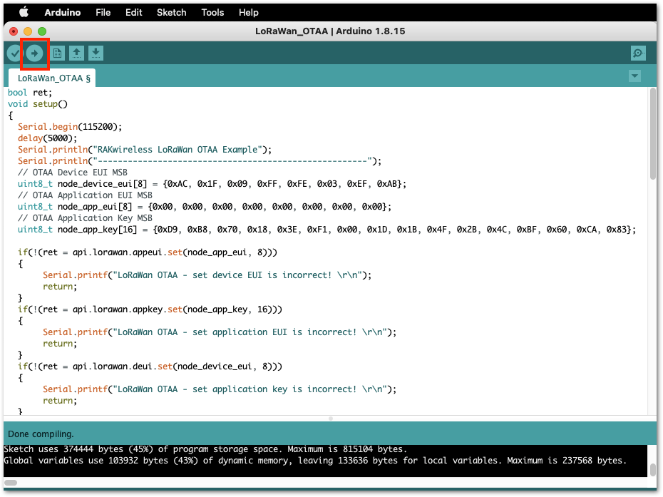 Figure 1: Uploading the code
- You should now be able to view the terminal logs in the Serial Monitor of the Arduino IDE. There are times the COM port may be disconnected, preventing you from viewing of the terminal output immediately. In such cases, you can reconnect the module or try pressing the reset button to see the terminal output.
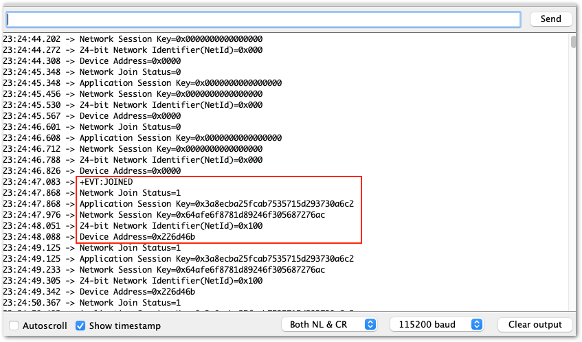 Figure 1: Output logs
- Check on the LoRaWAN network server logs of RAK7268 if your device has been successfully joined with the
join requestandjoin acceptlogs.
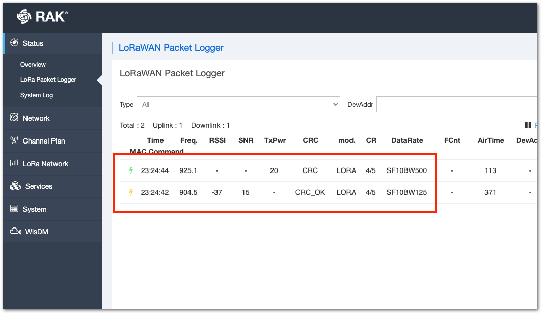 Figure 1: WisGate LoRa packet logger
More examples for the RAK4630 can be found in the RUI3-Best-Practices on Github.
RAK4630 as a Lora/Lorawan Modem via AT Command
This section covers the guide on how to use RAK4630 as a LoRa/LoRaWAN modem via AT command.
AT Command via UART1
RAK4630 module can be configured using AT commands via the UART1 interface. You will need a USB to UART TTL adapter to connect the RAK4630 to your computer's USB port and a serial terminal tool. It is highly recommended to use the RAK Serial Port Tool so you can easily send AT commands and view the replies from the console output. You can configure the RAK4630 in two ways:
- LoRaWAN End-Device - RAK4630 as LoRaWAN IoT device.
- LoRa P2P - Point-to-point communication between two RAK4630 modules.
Connect to the RAK4630
- Connect the RAK4630 to the serial port of a general-purpose computer (USB port) using a USB to UART TTL adapter like RAKDAP1, as shown in Figure 41.
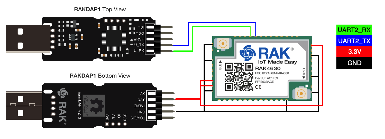 Figure 1: RAK4630 module connection
You can also send AT commands via direct USB connection to the module, as shown in hardware setup.
- Any serial communication tool can be used, but it is recommended to use the RAK Serial Port Tool.
- Configure the serial communication tool by selecting the proper port detected by the computer and configure the link as follows:
- Baud Rate: 115200 baud
- Data Bits: 8 bits
- Stop Bits: 1 stop bit
- Parity: NONE
Configure RAK4630 as LoRaWAN End-device
To enable the RAK4630 module as a LoRaWAN end-device, a device must be registered first in the LoRaWAN network server. This guide will cover both TTN and Chirpstack LoRaWAN network servers and the associated AT commands for the RAK4630.
This guide covers the following topics:
- TheThingsNetwork Guide: How to log in, register new accounts, and create new applications on TTN.
- RAK4630 TTN OTAA Guide: How to add OTAA device on TTN and what AT commands to use on RAK4630 OTAA activation.
- RAK4630 TTN ABP Guide: How to add ABP device on TTN and what AT commands to use on RAK4630 ABP activation.
- Chirpstack Guide: How to create new applications on Chirpstack.
- RAK4630 Chirpstack OTAA Guide: How to add OTAA device to Chirpstack and what AT commands to use on RAK4630 OTAA activation.
- RAK4630 Chirpstack ABP Guide: How to add ABP device on Chirpstack and what AT commands to use on RAK4630 ABP activation.
Connecting to The Things Network (TTN)
This section illustrates how to connect the RAK4630 module to the TTN platform.
You need to have a functioning gateway connected to TTN, or you must be within the coverage of a TTN community network.
 Figure 1: The Things Stack
As shown in Figure 42, The Things Stack (TTN V3) is an open-source LoRaWAN Network Server suitable for global, geo-distributed public and private deployments, as well as for small local networks. The architecture follows the LoRaWAN Network Reference Model for standards compliance and interoperability. This project is actively maintained by The Things Industries.
LoRaWAN is a protocol for low-power wide-area networks. It allows for large-scale Internet of Things deployments where low-powered devices efficiently communicate with Internet-connected applications over long-range wireless connections.
The RAK4630 WisDuo module can be part of this ecosystem as a device, and the objective of this section is to demonstrate how simple it is to send data to The Things Stack using the LoRaWAN protocol. To achieve this, the RAK4630 WisDuo module must be located inside the coverage of a LoRaWAN gateway connected to The Things Stack server.
Registration to TTN and Creating LoRaWAN Applications
- The first step is to visit The Things Network website and create an account, as depicted in Figure 43. Next, choose a cluster, as illustrated in Figure 45.
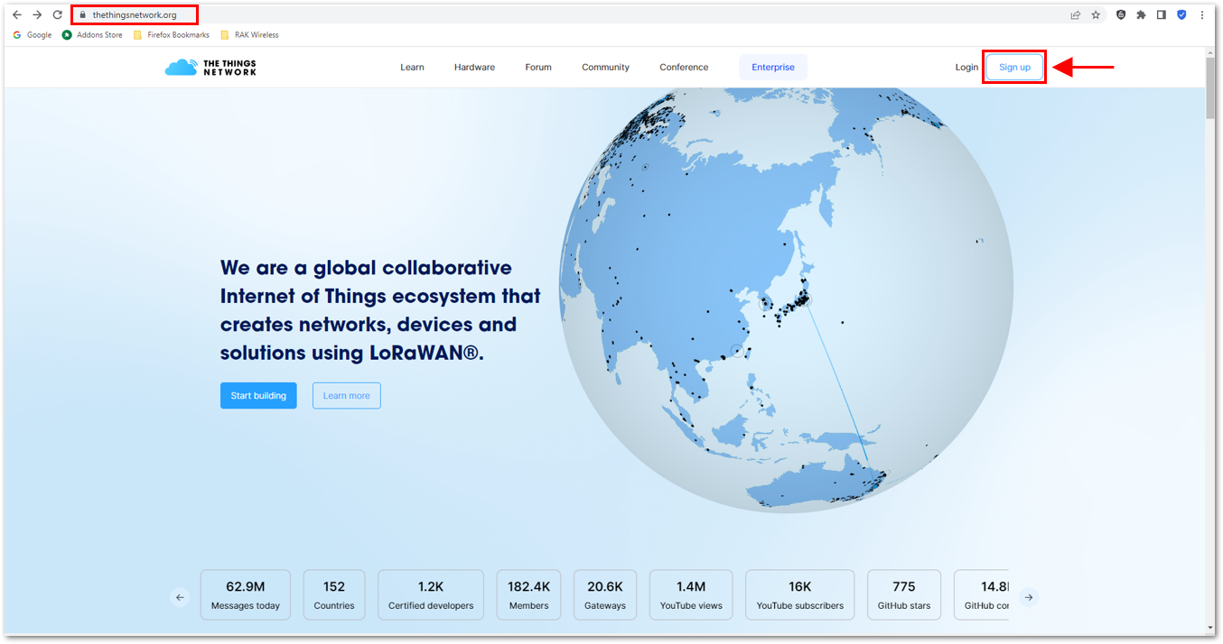 Figure 1: Signing up an account in TTN
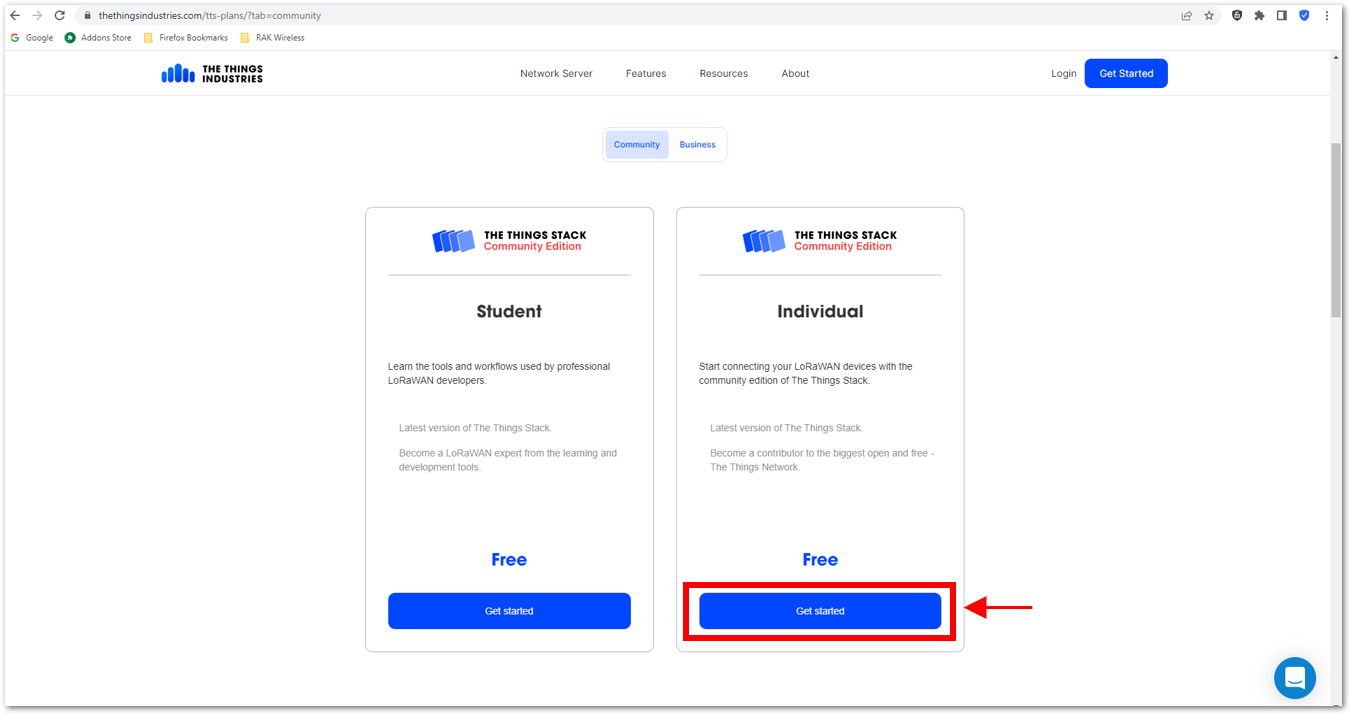 Figure 1: Signing up an account in TTN
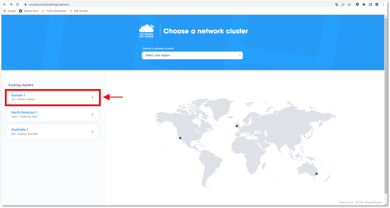 Figure 1: Selecting Cluster in TTN
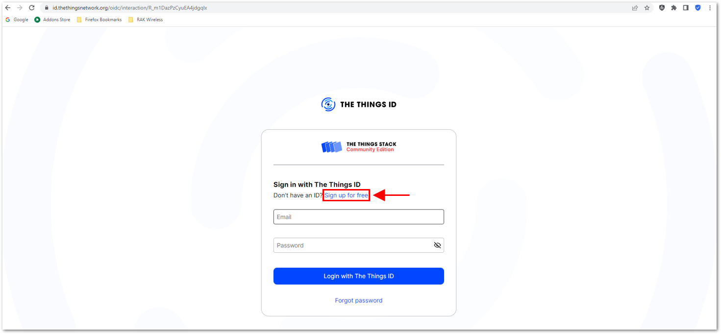 Figure 1: Signing up through the Things ID
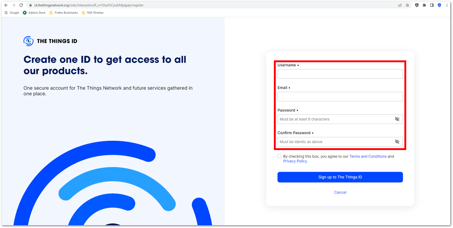 Figure 1: Creation of an account through the Things ID
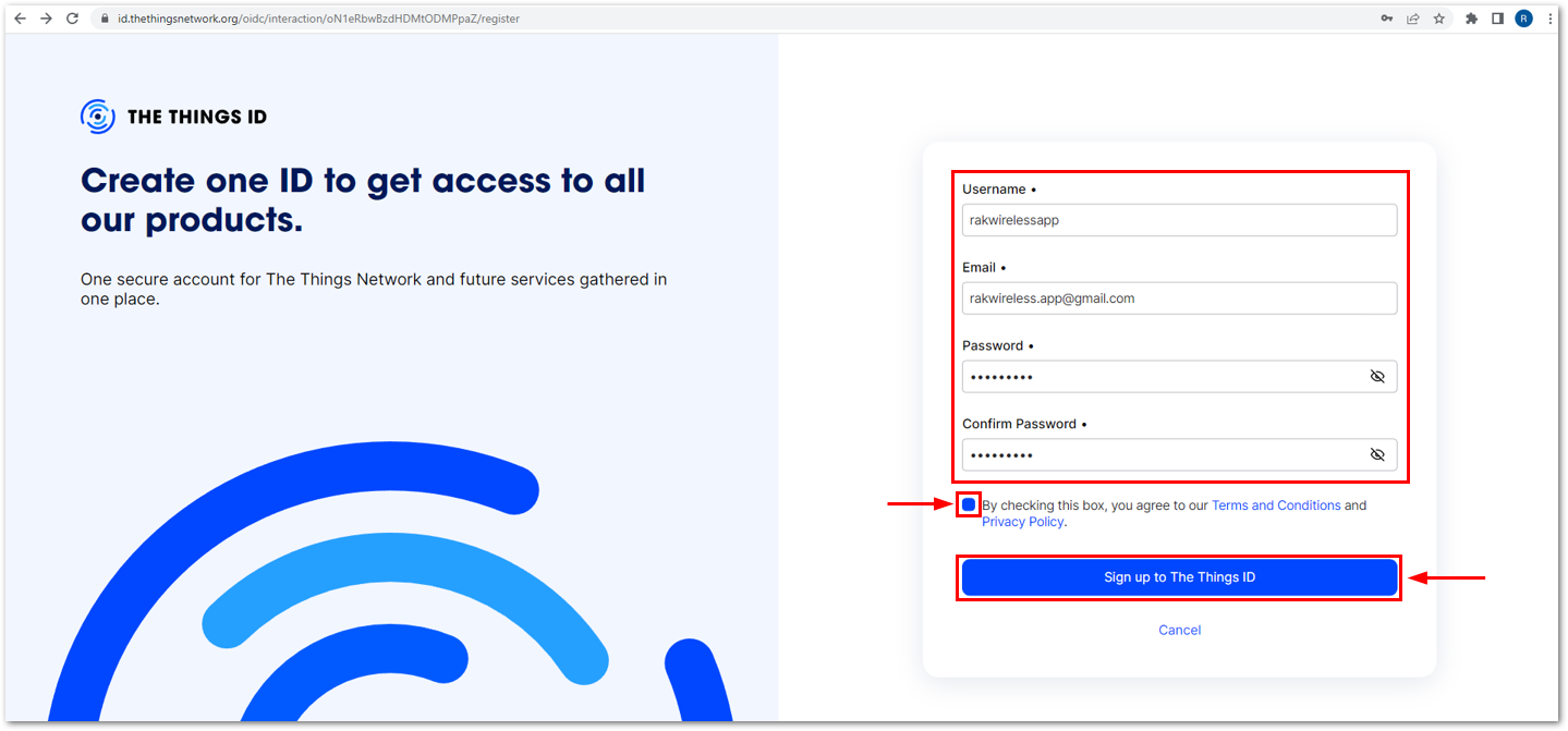 Figure 1: Creation of an account through the Things ID
You can use the same login credentials on the TTN V2 if you have one. If you have no account yet, you need to create one.
- Now that you are logged in to the platform, the next step is to create an application. Click Create an application.
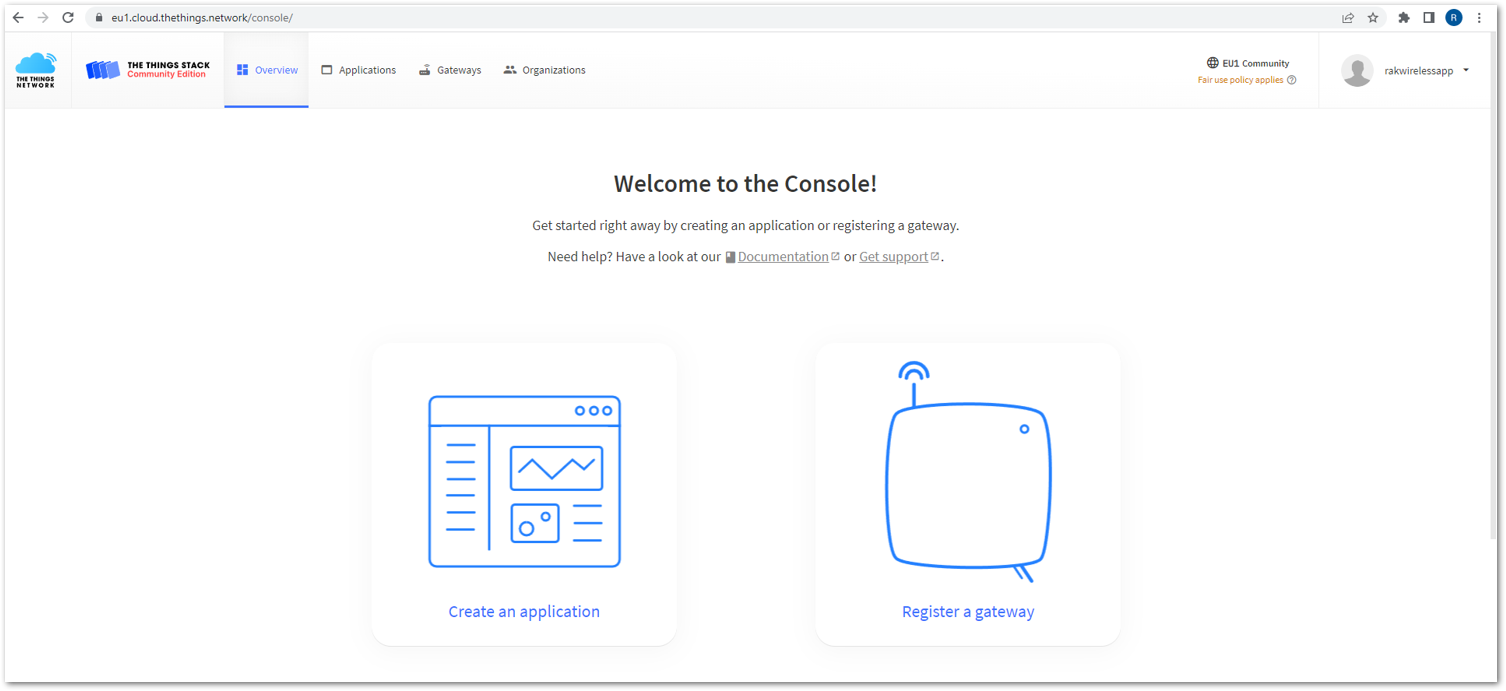 Figure 1: The Things Stack Platform
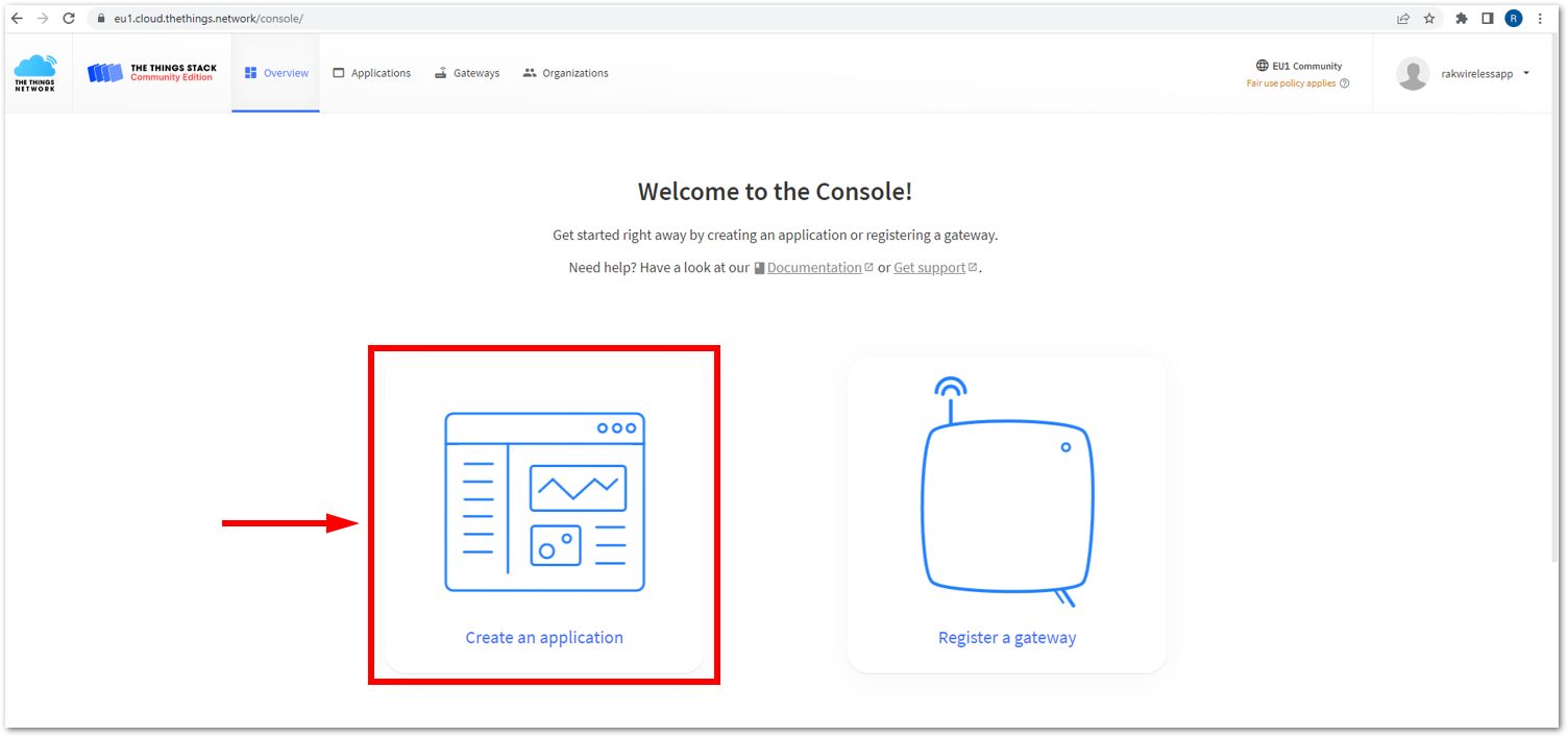 Figure 1: Creating TTN application for your LoRaWAN devices
- To register an application, enter the required details and necessary information about your application, then click Create application.
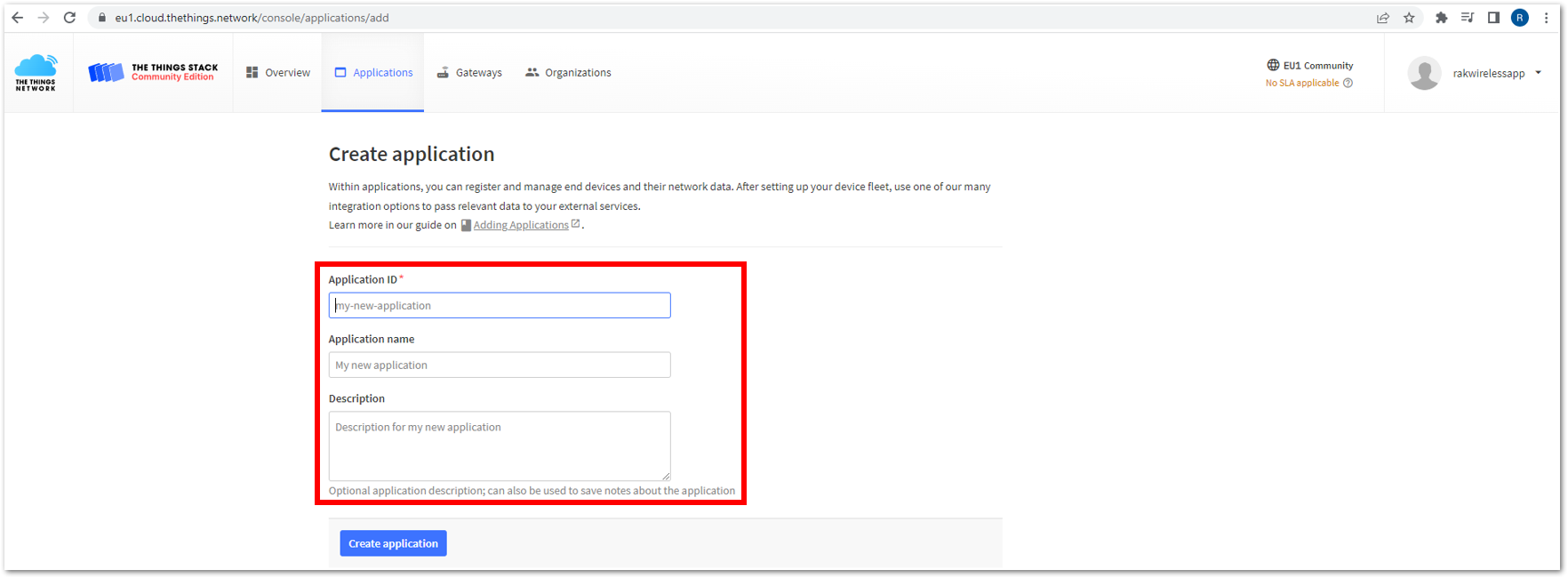 Figure 1: Details of the TTN application
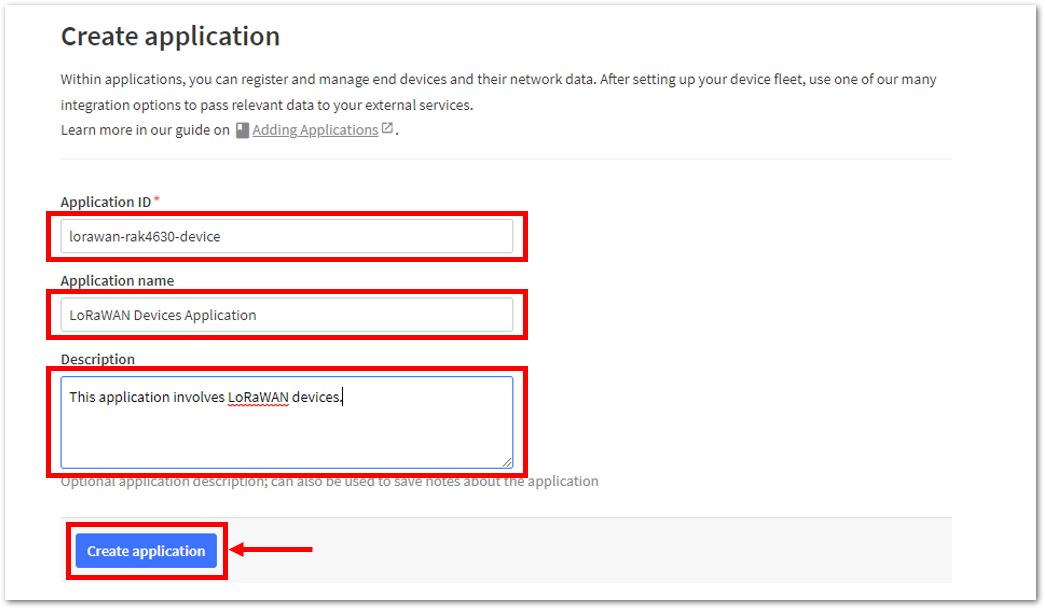 Figure 1: Details of the TTN application
- If you have no error in the previous step, you should now be on the application console page. The next step is to add end-devices to your TTN application.
LoRaWAN specifications enforce that each end-device has to be personalized and activated. There are two options in registering devices depending on the activation mode selected. Activation can be done either via Over-The-Air-Activation (OTAA) or Activation-By-Personalization (ABP).
TTN OTAA Device Registration
- Go to your application console to register a device. To start adding an OTAA end-device, click + Register end device, as shown in Figure 53.
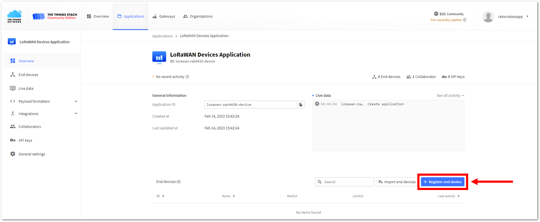 Figure 1: Register end device
- To register the board, click the Enter end device specifics manually.
 Figure 1: Enter end device specifics manually
- Next step is to set up the Frequency plan, compatible LoRaWAN version, and Regional Parameters version supported. Then provide the JoinEUI credentials by entering zeroes into it.
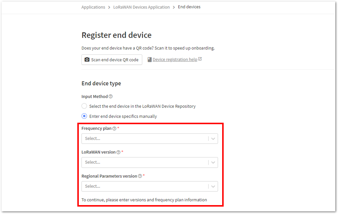 Figure 1: Setting up for your device
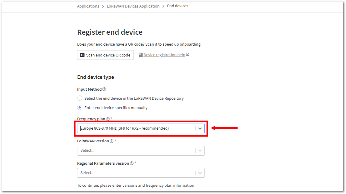 Figure 1: Setting up for your device
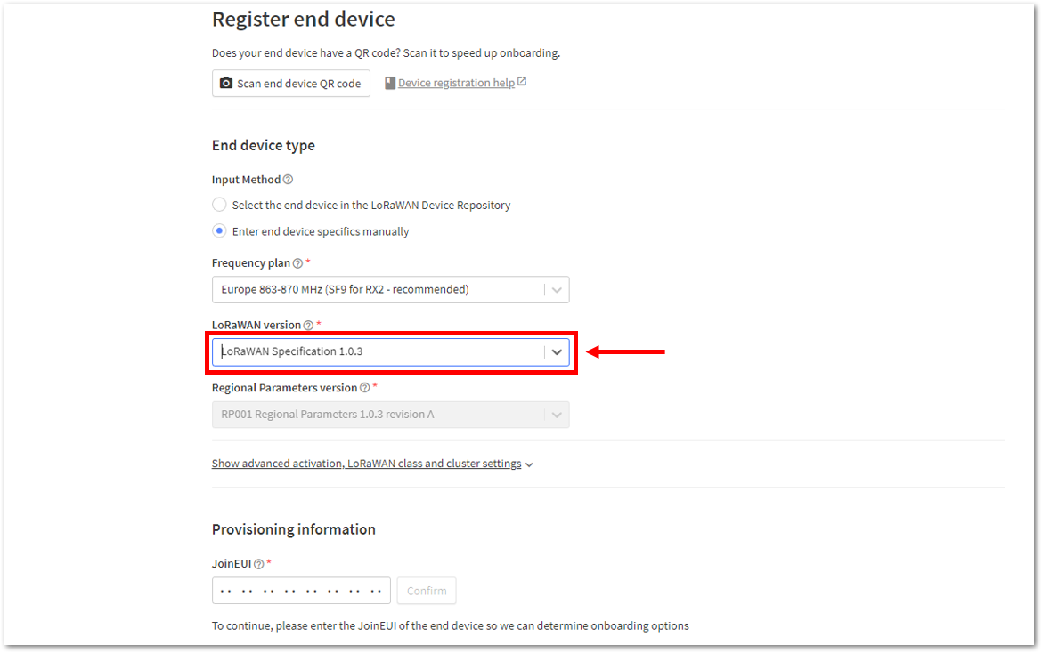 Figure 1: Setting up for your device
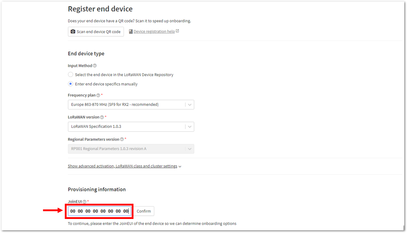 Figure 1: Setting up for your device
- Then click Show advanced activation, LoRaWAN class and cluster settings. Configure the activation mode by selecting Over the air activation (OTAA) and Additional LoRaWAN class capabilities to class A only. Then click Confirm.
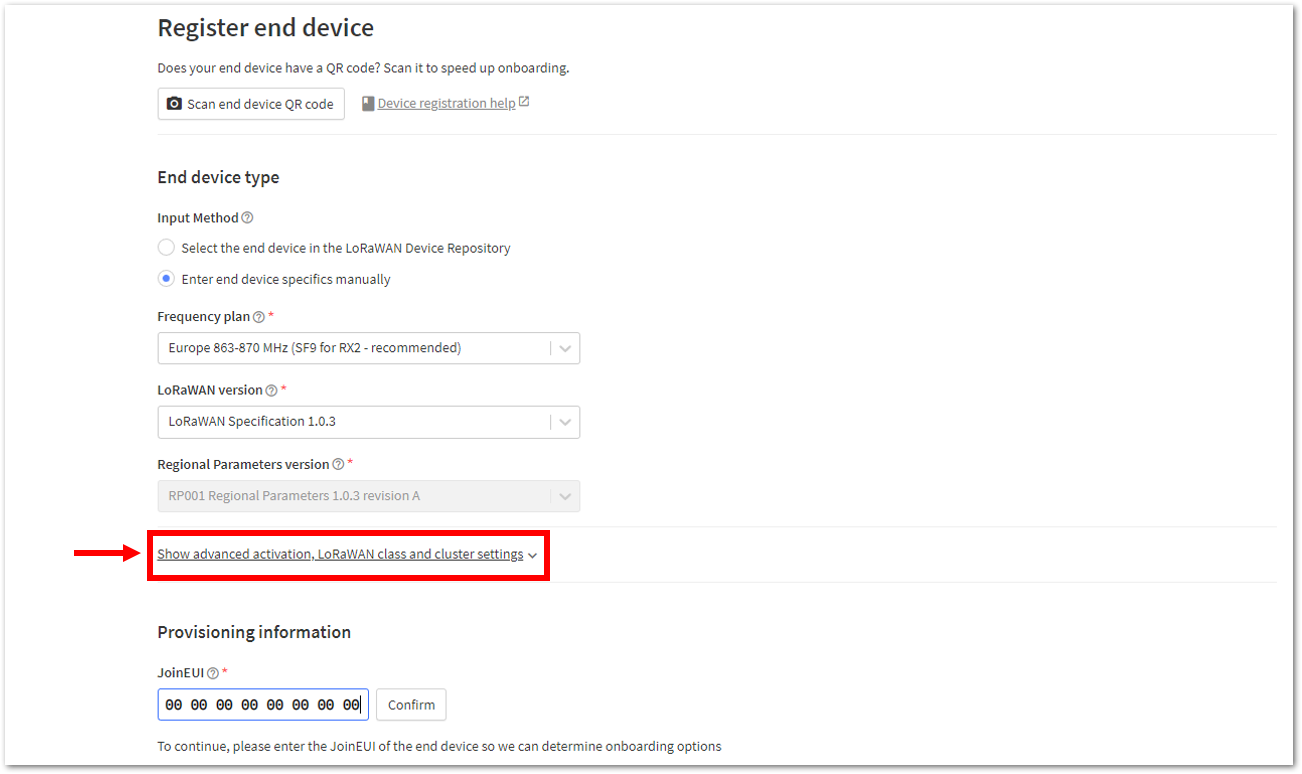 Figure 1: Setting up for your device
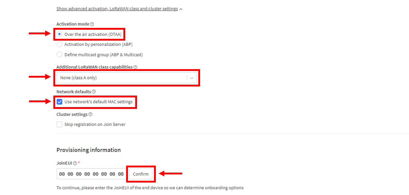 Figure 1: Setting up for your device
- Once done, provide the DevEUI credentials of your device into the DevEUI portion. This will automatically generate the specific End device ID of your board. Then click Generate under AppKey under the Provisioning information section. Finally, click Register end device.
-
The AppEUI, DevEUI, and AppKey are hidden in this section as these are unique from a specific device. The DevEUI credential is unique to every RAK4630 device. Also, you should generate your own AppEUI and AppKey credentials for your specific device and application.
-
The AppEUI is the same as JoinEUI.
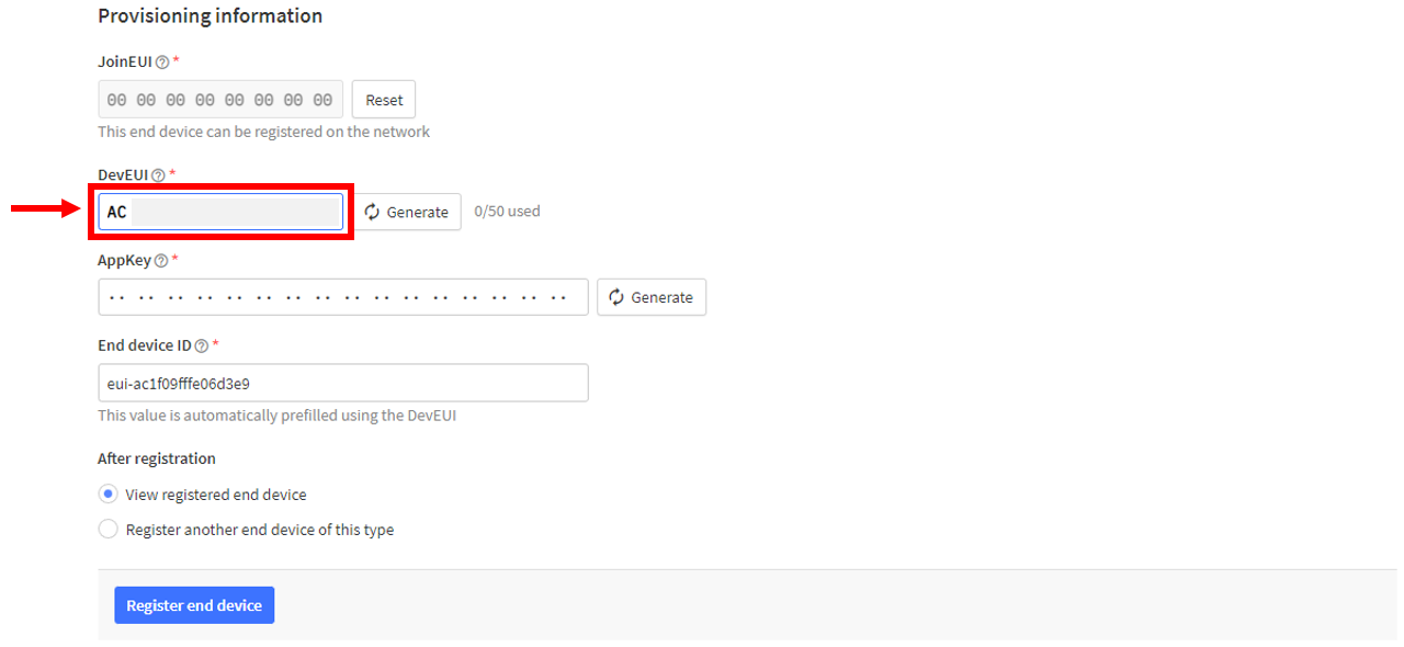 Figure 1: Setting up for your device
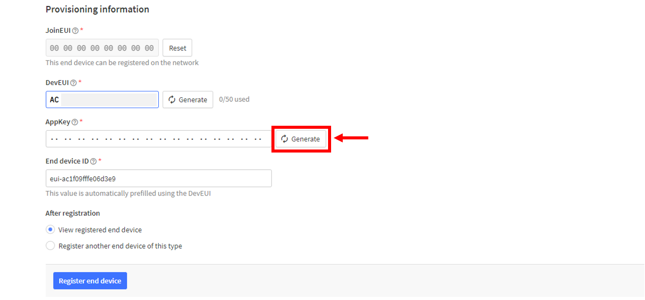 Figure 1: Setting up for your device
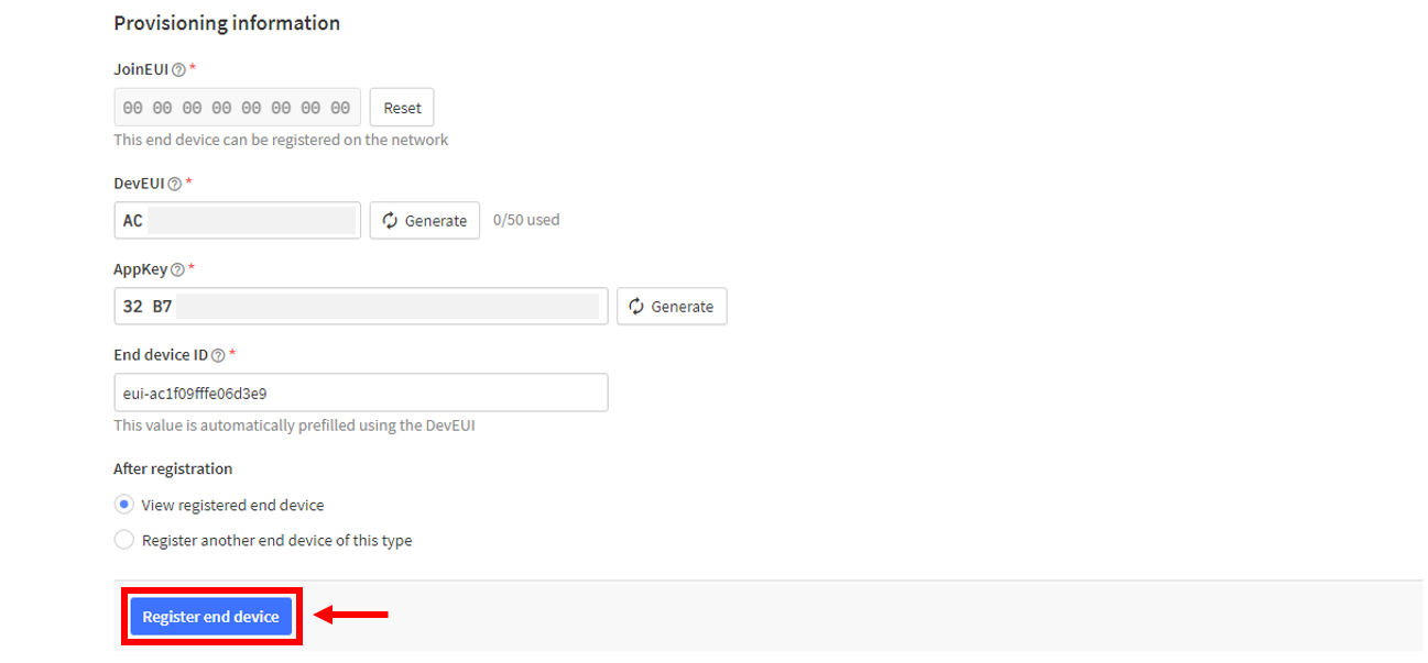 Figure 1: Register end device
- You should now be able to see the device on the TTN console after you fully register your device, as shown in Figure 64.
-
The AppEUI, DevEUI, and AppKey are the parameters that you will need to activate your LoRaWAN end-device via OTAA. The AppKey is hidden by default for security reasons, but you can easily show it by clicking the show button. You can also copy the parameters quickly using the copy button.
-
The three OTAA parameters on the TTN device console are MSB by default.
-
These parameters are always accessible on the device console page.
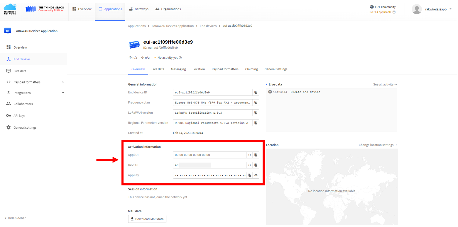 Figure 1: OTAA device successfully registered to TTN
OTAA Configuration for TTN
The RAK4630 module can be configured using WisToolBox for OTAA setup. WisToolBox is a software tool designed to support the RAK4630 module. It automatically detects the RAK4630 module once connected to the PC. Below are the options available in WisToolBox for performing the OTAA configuration.
OTAA Configuration for TTN via WisToolBox UI
The RAK4630 should have the correct OTAA credentials to connect to TTN. This can be done using WisToolBox UI. Below are the steps on setting up your RAK4630 using WisToolBox.
- Connect your RAK4630 to the PC via USB cable and open the WisToolBox application.
- Click the CONNECT DEVICE button to launch the WisToolBox Dashboard.
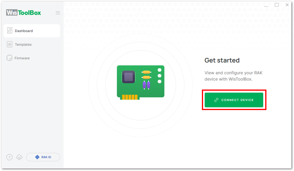 Figure 1: CONNECT DEVICE
- Then select your target port where your RAK4630 is connected. Once recognized, click CONNECT, as shown in Figure 67.
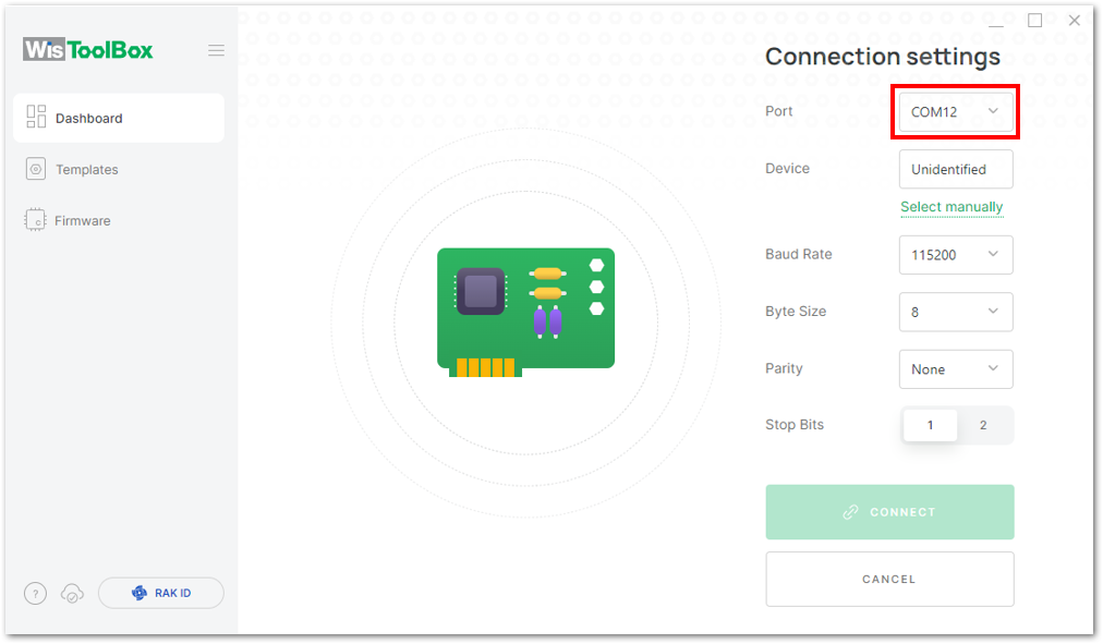 Figure 1: Setting up your device
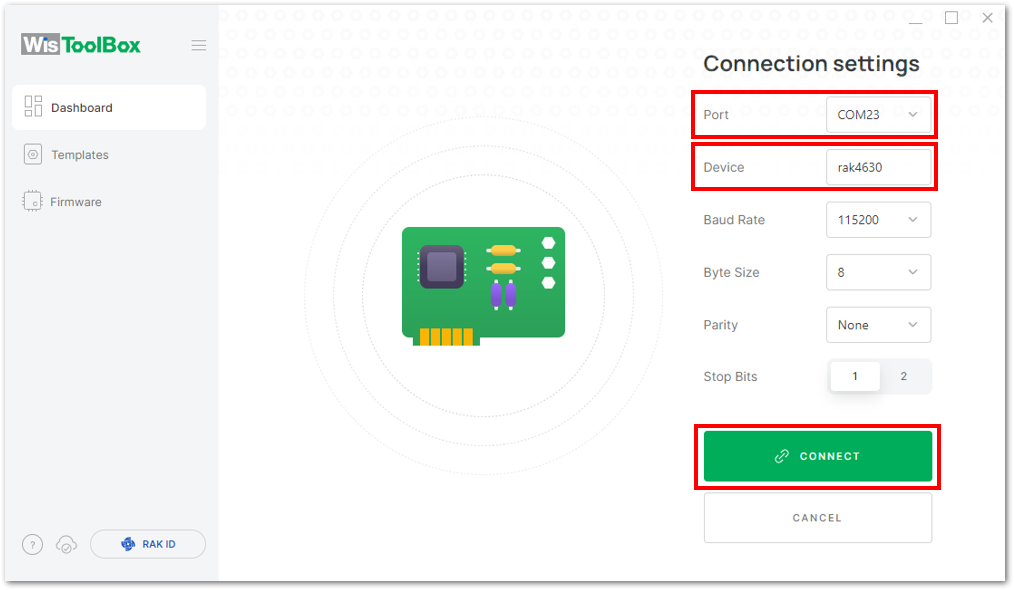 Figure 1: Setting up your device
- Once done, the RAK4630 will appear in the dashboard then select it.
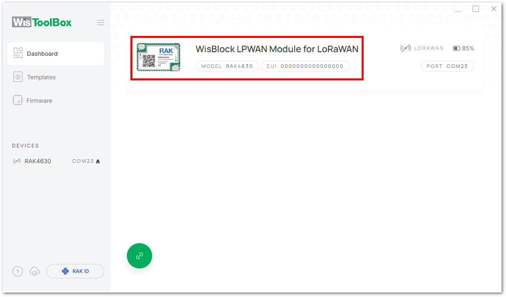 Figure 1: Device seen from WisToolBox dashboard
- Next, click on PARAMETERS to configure your RAK4630.
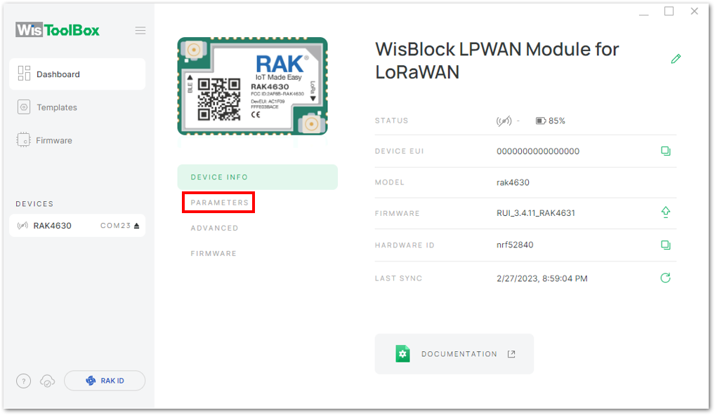 Figure 1: Setting up your device
- Click on Global settings to set the network mode to LoRaWAN and the join mode to OTAA. Ensure that the active region is set to EU868 for this configuration. If you intend to operate in other regional bands, you can select the appropriate active region based on your location.
- LoRa network mode: LoRaWAN
- LoRaWAN join mode: OTAA
- LoRaWAN region: EU868
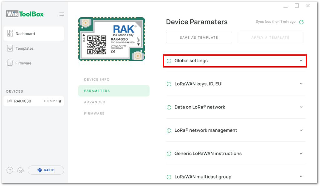 Figure 1: Global settings
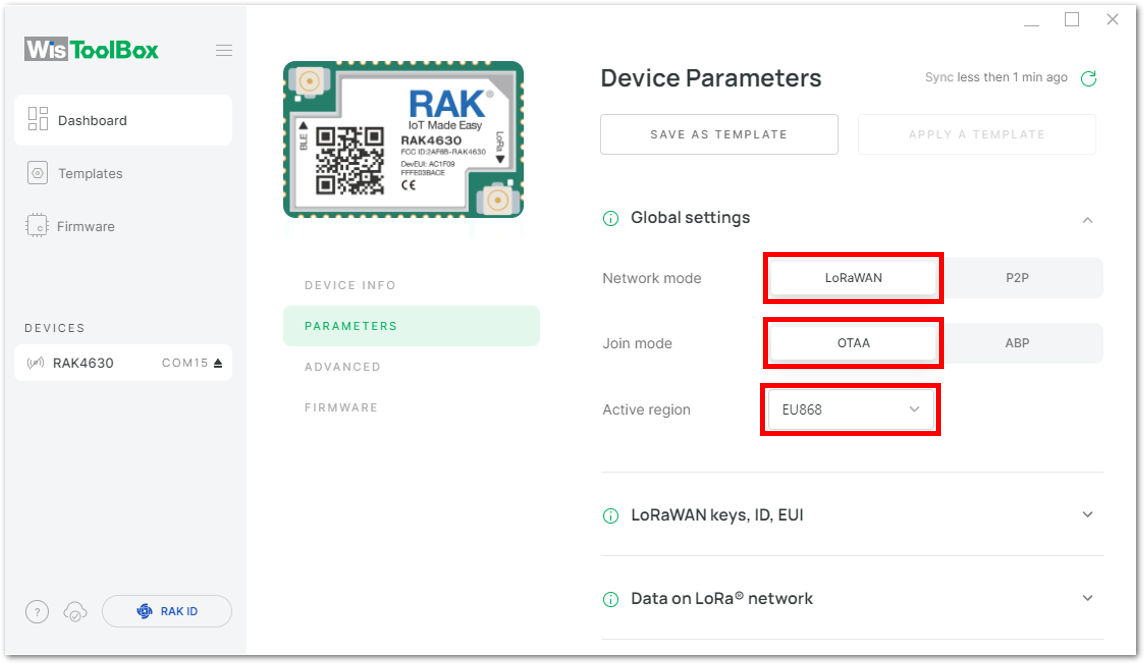 Figure 1: Global settings
- Configure the Application EUI (AppEUI), Application key (AppKey) and Device EUI (DevEUI).
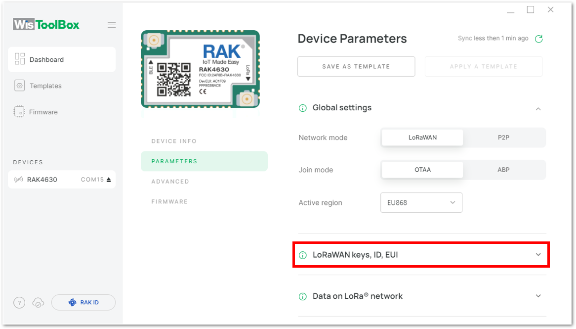 Figure 1: LoRaWAN keys, ID, EUI
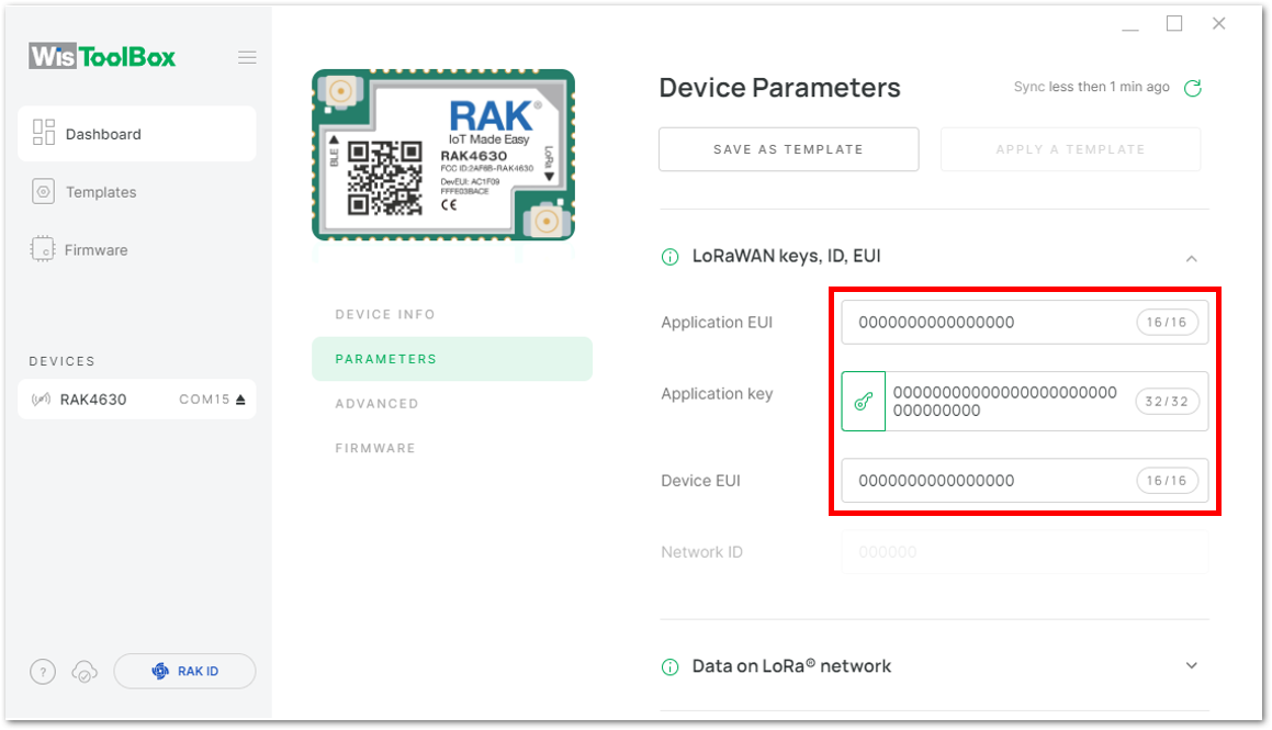 Figure 1: Setting up your device
- Return to the console where your RAK4630 end-device was previously created and copy all the credentials from there. These credentials will also be used in the WisToolBox dashboard. Once entered into the dashboard, click on APPLY COMMAND to update your device, as illustrated in Figure 81.
- The AppEUI, DevEUI, and AppKey are hidden in this section as these are unique from a specific device.
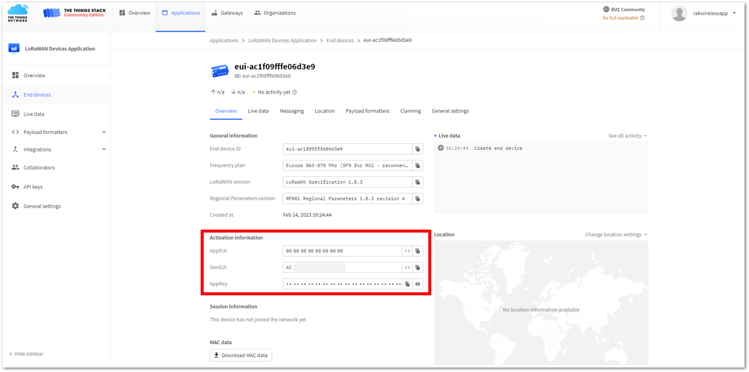 Figure 1: Your created OTAA device from your console
- For Application EUI (AppEUI)
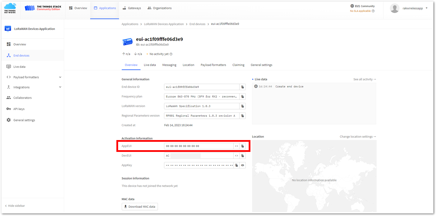 Figure 1: Copying the AppEUI credential from TTN to WisToolBox
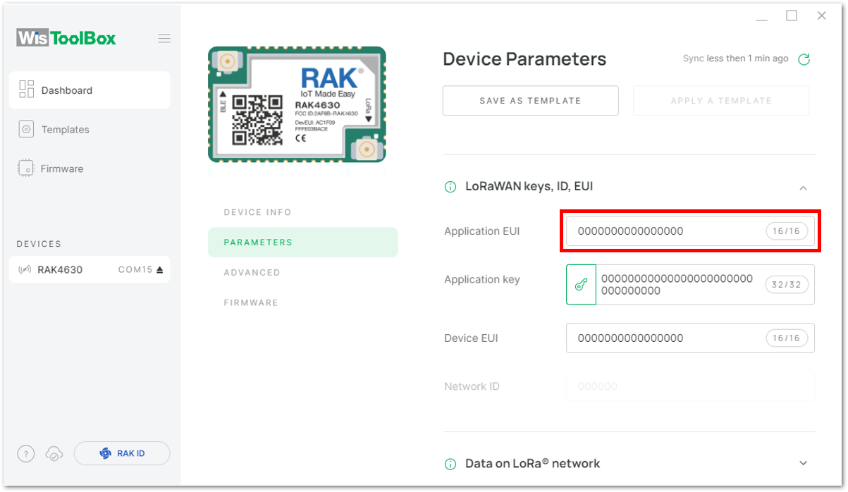 Figure 1: Copying the AppEUI credential from TTN to WisToolBox
- For Application key (AppKey)
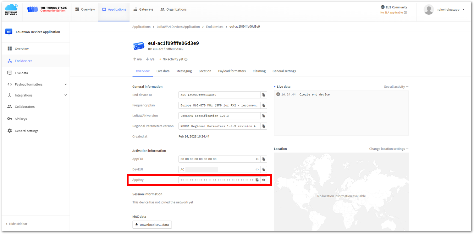 Figure 1: Copying the AppKey credential from TTN to WisToolBox
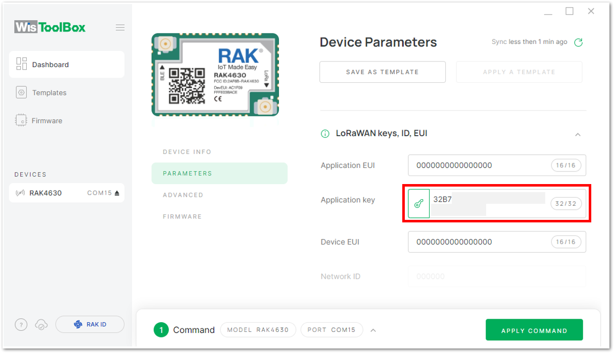 Figure 1: Copying the AppKey credential from TTN to WisToolBox
- For Device EUI (DevEUI)
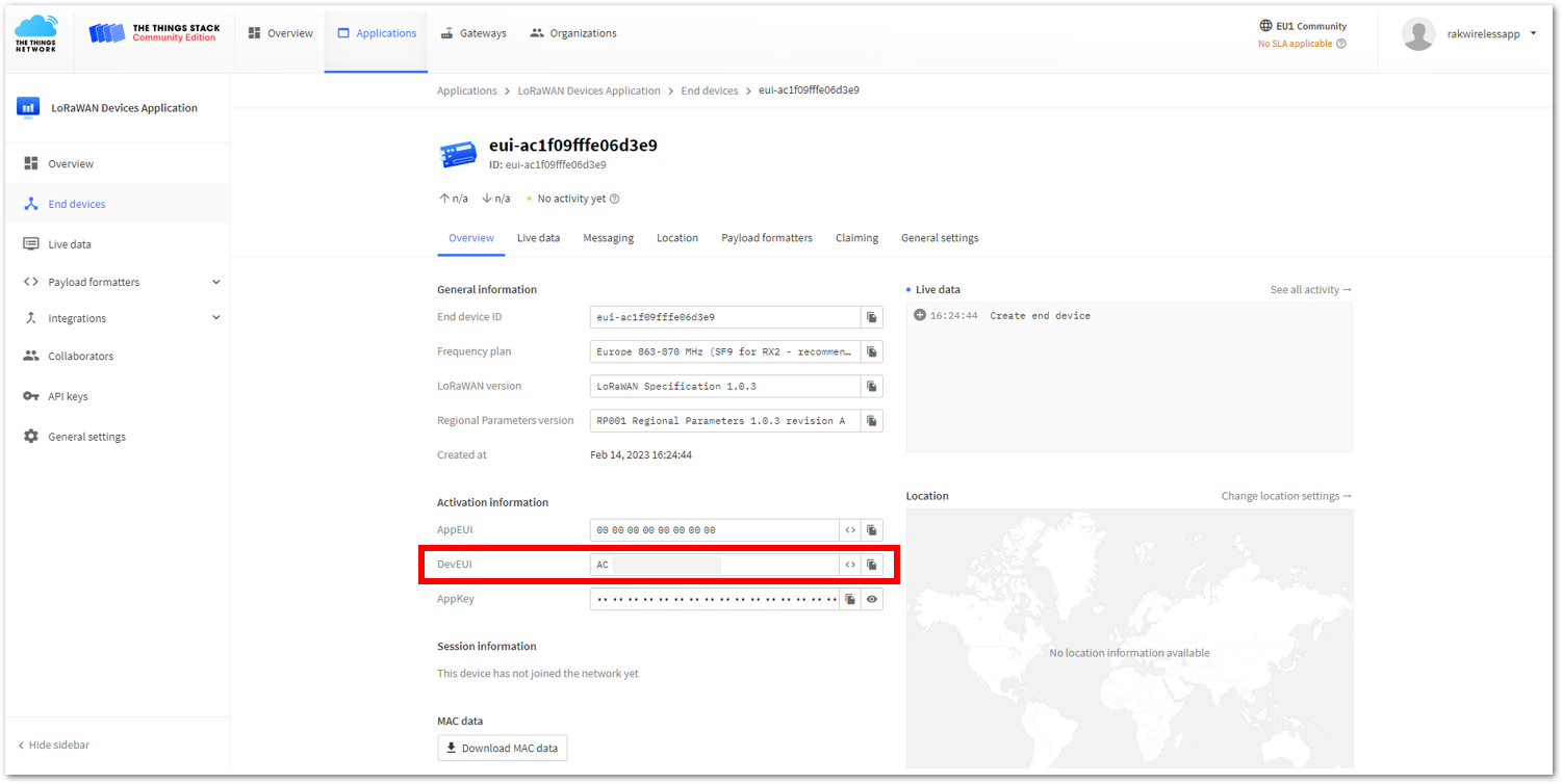 Figure 1: Copying the DevEUI credential from TTN to WisToolBox
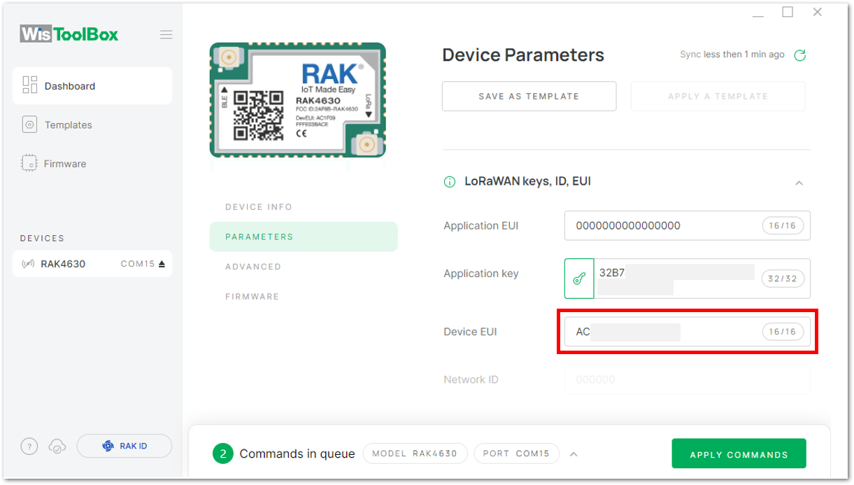 Figure 1: Copying the DevEUI credential from TTN to WisToolBox
- WisToolBox Dashboard
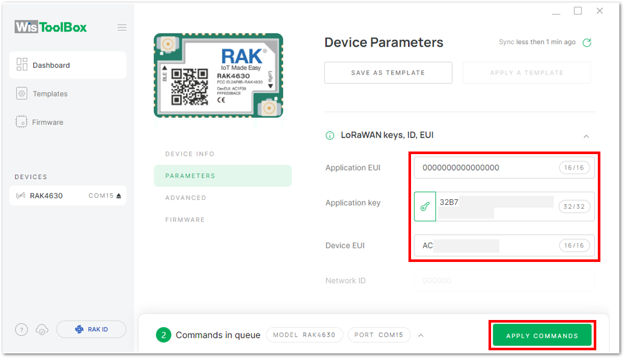 Figure 1: Used credentials from your console in WisToolBox dashboard
- Once completed, you will see a summary of the commands that have been applied to your device, then click on CLOSE.
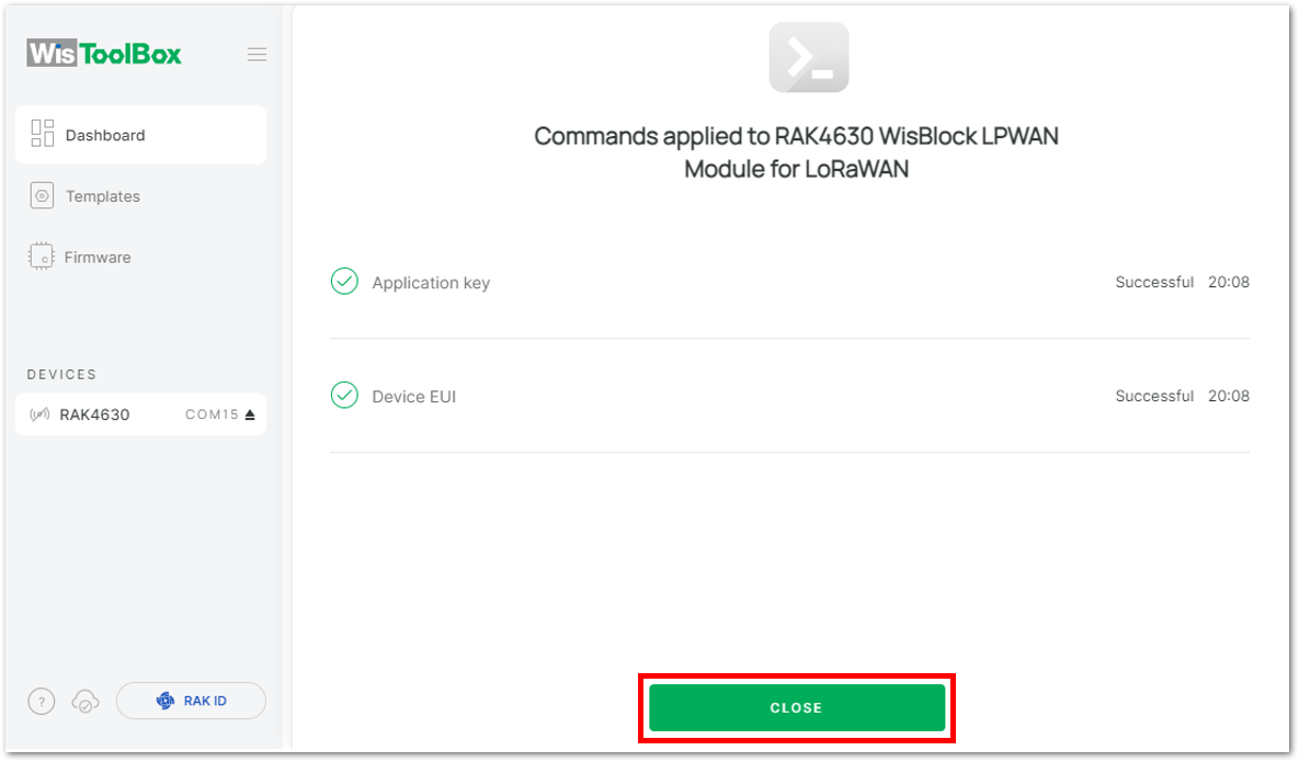 Figure 1: Summary of commands
- You will then return to the dashboard with updated credentials of your device.
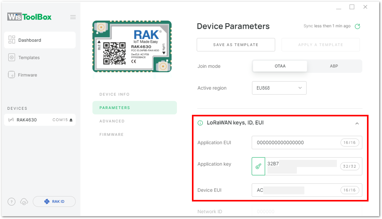 Figure 1: Successfully configured OTAA device via WisToolBox dashboard
- After updating your device's credentials, it can now join the network. To do this, navigate to Data on LoRa network under PARAMETERS. Then, click on JOIN NETWORK under LoRaWAN join settings. After a few seconds, it will notify you that your OTAA device has successfully joined the TTN server. You can also check your TTN console to confirm if your device has successfully joined TTN.
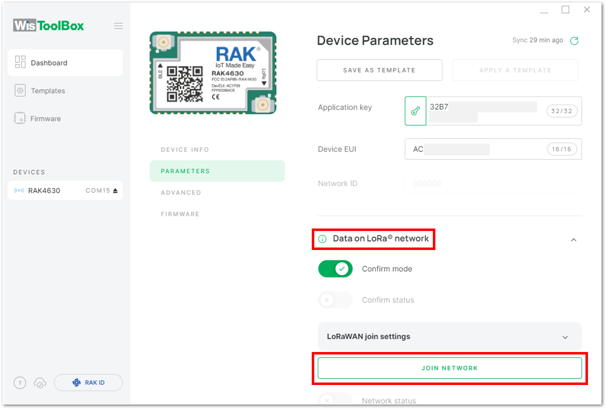 Figure 1: Joining mode of your OTAA device
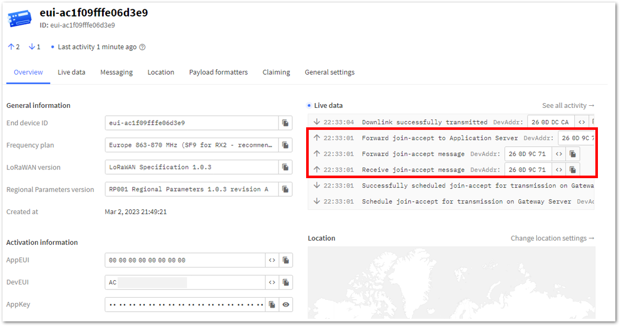 Figure 1: OTAA device successfully joined the TTN server
OTAA Configuration for TTN via WisToolBox Console
Here's another way of OTAA configuration using WisToolBox Console. Below are the steps on setting up your RAK4630 using WisToolBox Console.
- Connect your RAK4630 to the PC via USB cable and open the WisToolBox application.
- Click the CONNECT DEVICE button to launch the WisToolBox Dashboard.
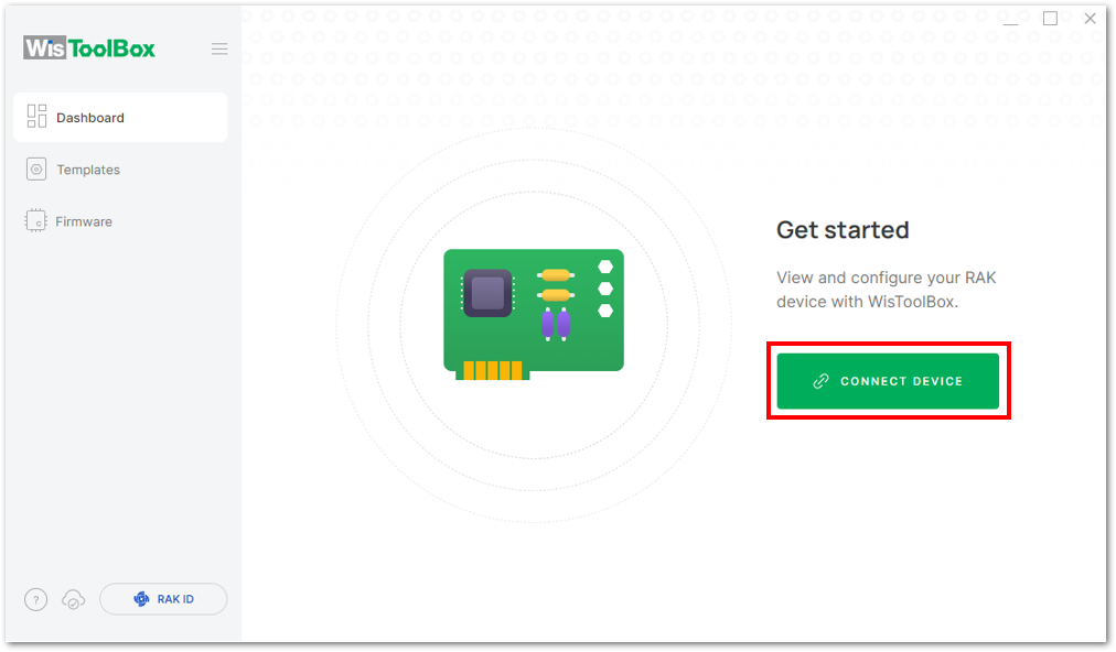 Figure 1: CONNECT DEVICE
- Then select your target port where your RAK4630 is connected. Once recognized, click CONNECT as shown in Figure 88.
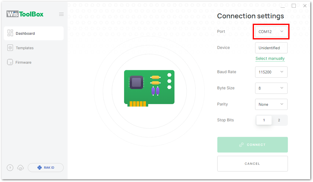 Figure 1: Setting up your device
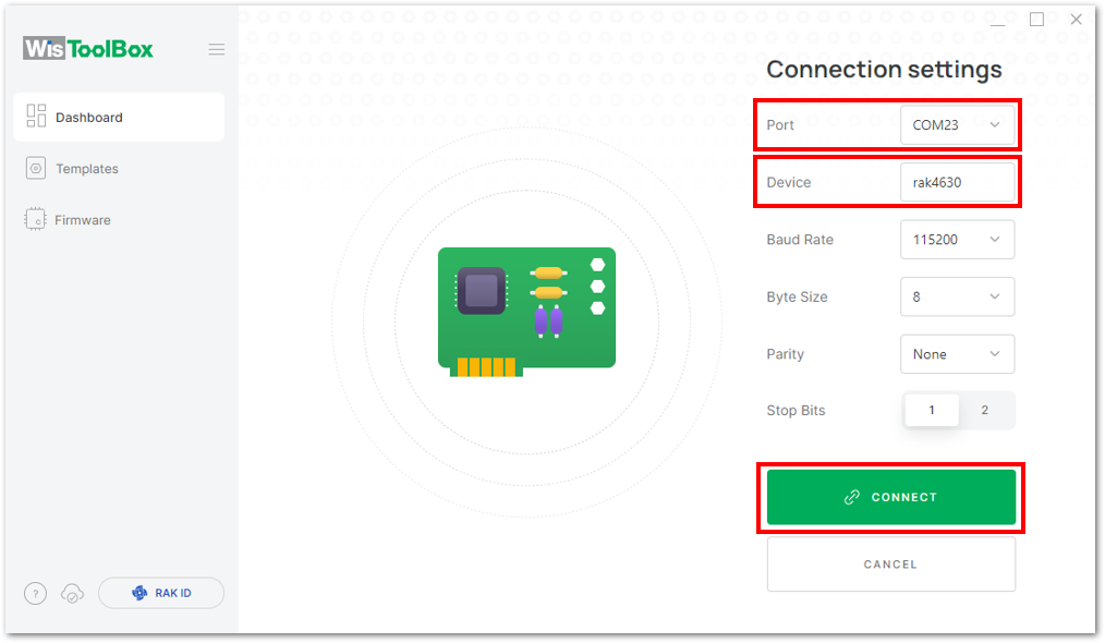 Figure 1: Setting up your device
- Once completed, the RAK4630 will appear in the dashboard. Select it from the list.
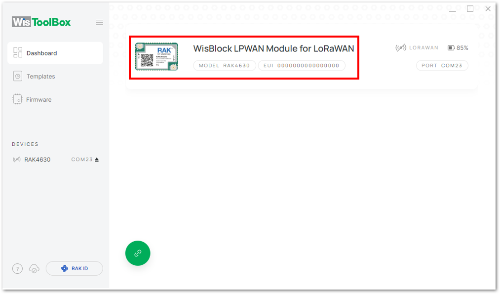 Figure 1: Device seen from WisToolBox dashboard
- Then, click ADVANCED.
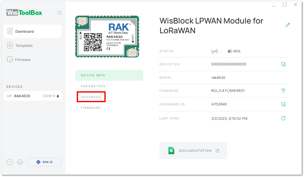 Figure 1: Setting up your device
- Click on OPEN CONSOLE to proceed with the configuration.
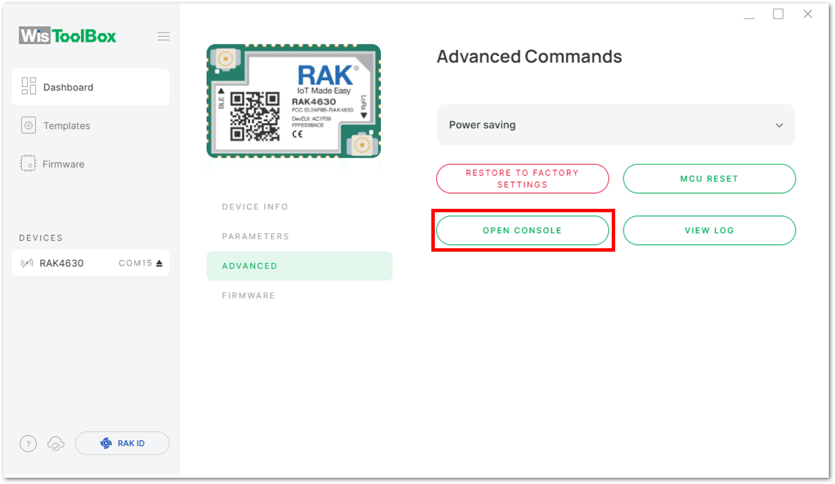 Figure 1: OPEN CONSOLE
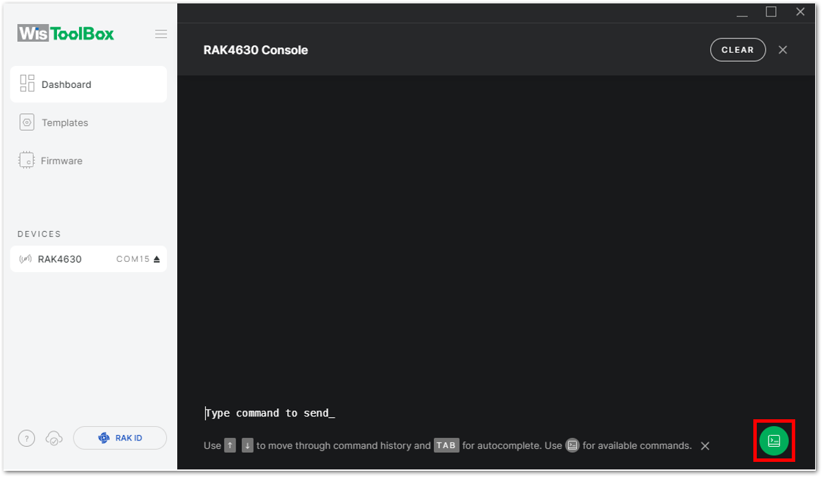 Figure 1: Opening the Console terminal of WisToolBox
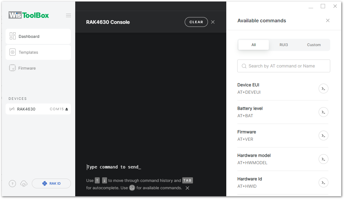 Figure 1: Opening the Console terminal of WisToolBox
- To begin the configuration, type
ATEto enable command echo for the configuration commands you input, and then press Enter.
It is recommended to start by testing the console and verify that the current configuration is working by sending these two AT commands:
AT
ATE
ATE is useful for tracking the commands and troubleshooting.
You will receive OK after inputting these two commands. Once ATE is set, you will see all the commands you input along with their replies.
If there is no OK or any reply, check if the device is powered correctly. If you are getting power from a USB port, ensure that you have a good USB cable.
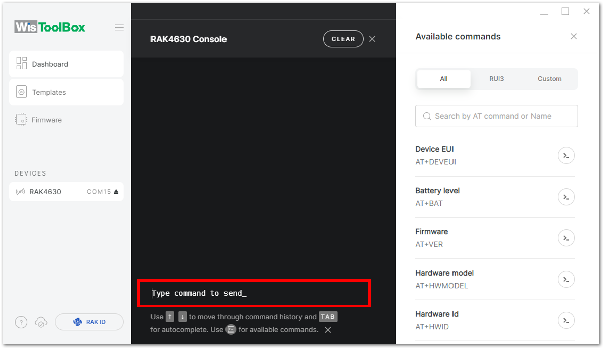 Figure 1: Setting up your Console
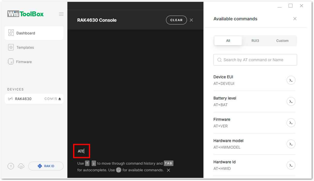 Figure 1: Setting up your Console
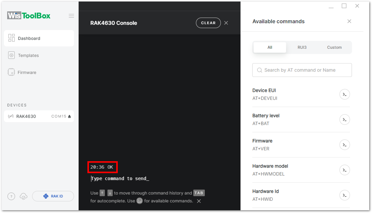 Figure 1: Setting up your Console
- Configure the LoRaWAN join mode to OTAA. Check what parameter you will input by typing
AT+NJM?and then Enter into the console terminal. For OTAA, inputAT+NJM=1and then press Enter as shown in Figure 97.
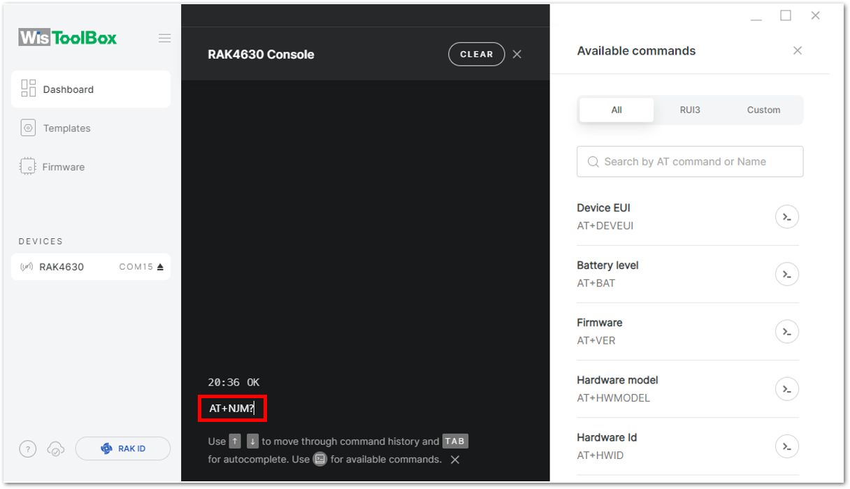 Figure 1: Setting up your Console
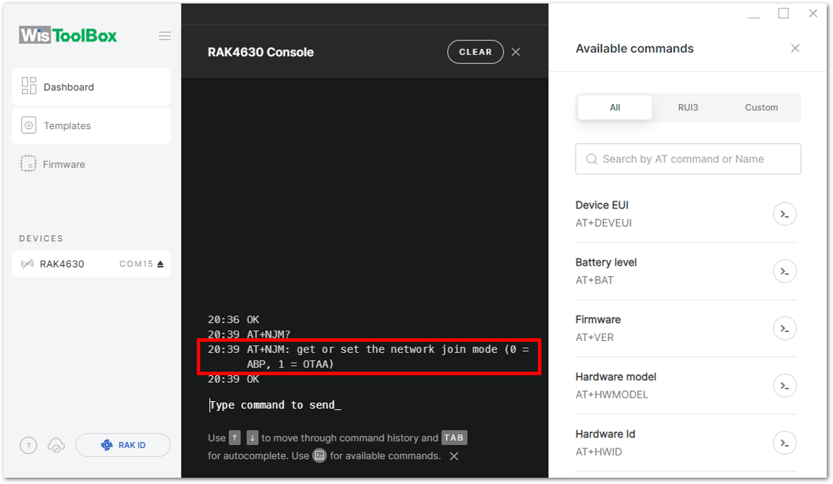 Figure 1: Setting up your Console
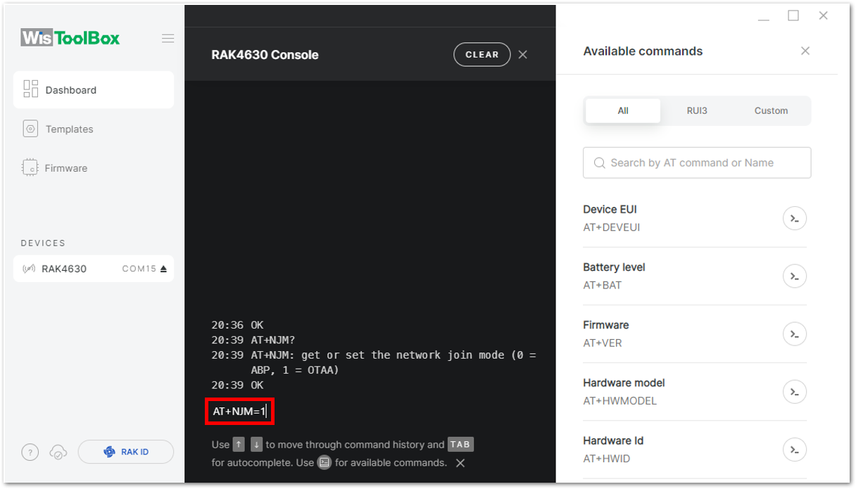 Figure 1: Setting up your Console
- Once done, set up your LoRaWAN region to EU868. Check what parameter you will input by typing
AT+BAND?and then Enter into the console terminal. For EU868, inputAT+BAND=4then press Enter. If you wish to work on other regional bands, you may check the list of band parameter options below.
Set the frequency/region to EU868.
AT+BAND=4
Depending on the Regional Band you selected, you might need to configure the sub-band of your RAK4630 to match the gateway and LoRaWAN network server. This is especially important for Regional Bands like US915, AU915, and CN470.
To configure the masking of channels for the sub-bands, you can use the AT+MASK command that can be found on the AT Command Manual.
To illustrate, you can use sub-band 2 by sending the command AT+MASK=0002.
| Code | Regional Band |
|---|---|
| 0 | EU433 |
| 1 | CN470 |
| 2 | RU864 |
| 3 | IN865 |
| 4 | EU868 |
| 5 | US915 |
| 6 | AU915 |
| 7 | KR920 |
| 8 | AS923-1 |
| 9 | AS923-2 |
| 10 | AS923-3 |
| 11 | AS923-4 |
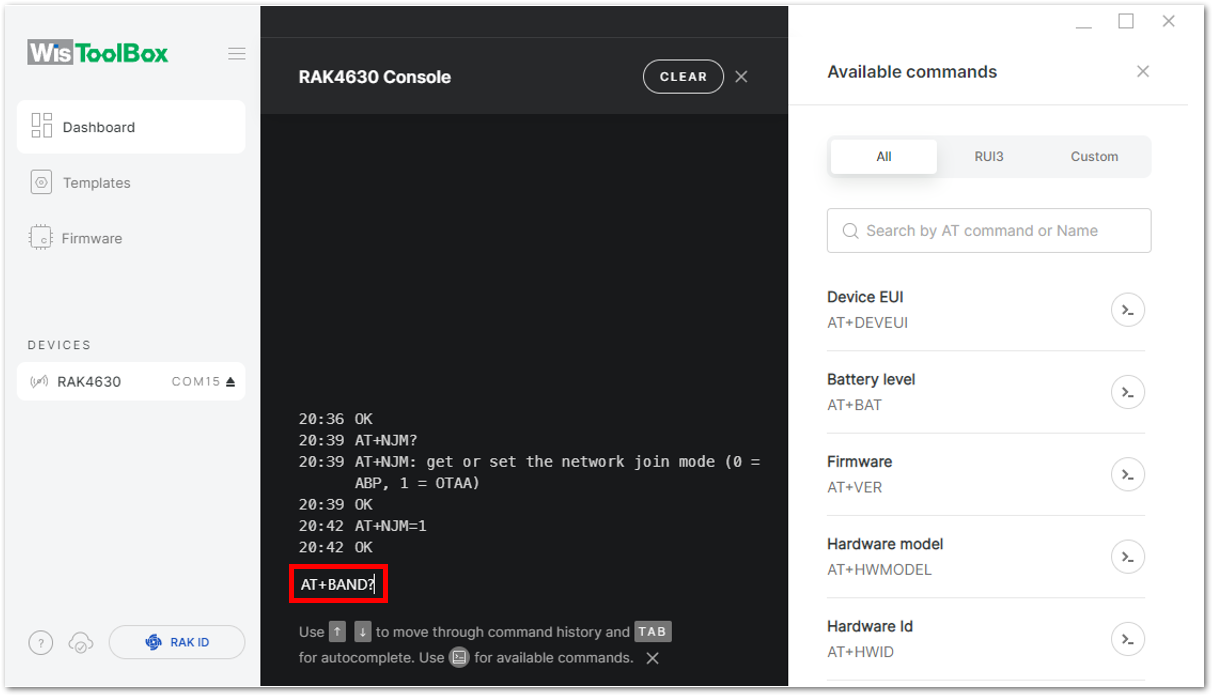 Figure 1: Setting up your Console
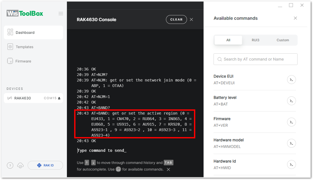 Figure 1: Setting up your Console
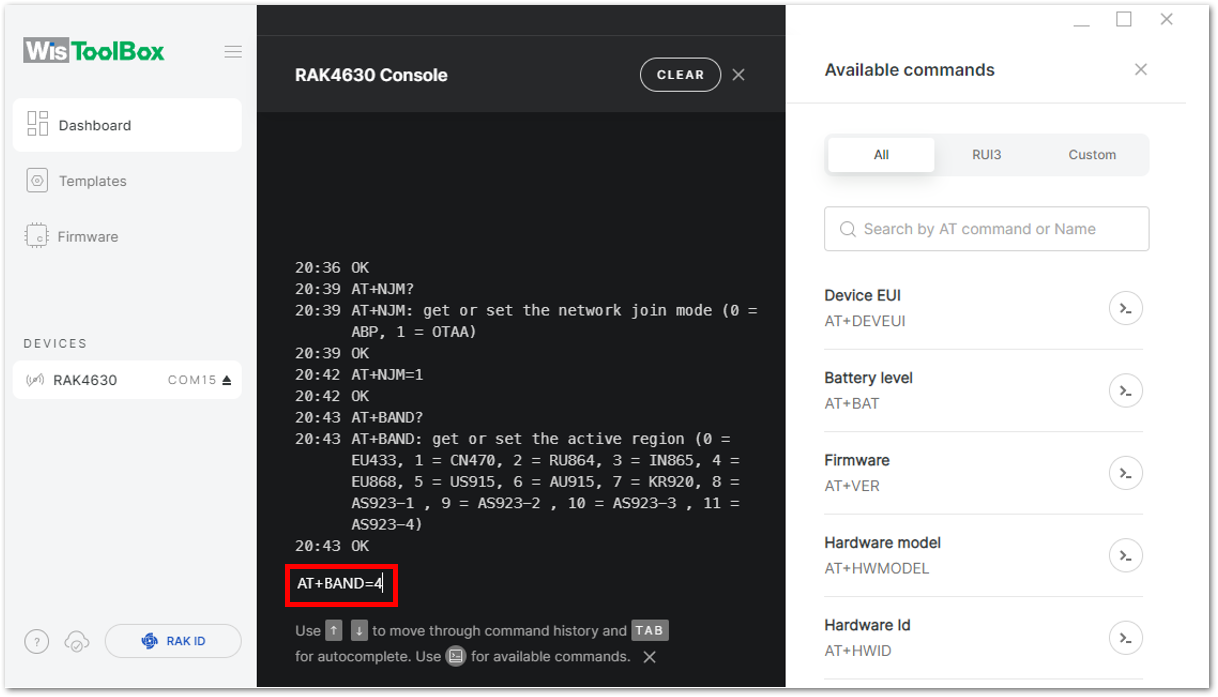 Figure 1: Setting up your Console
- Next, you need to update the OTAA credentials of your device, starting with the Application EUI (AppEUI). Return to the console where your RAK4630 End Device was created, copy the AppEUI credential, then paste it into the WisToolBox Console and press Enter.
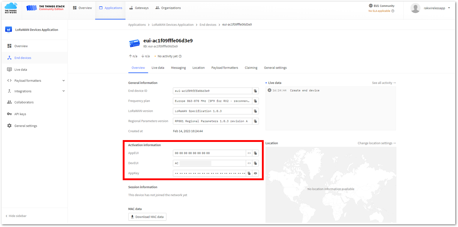 Figure 1: Your created OTAA device from your TTN console
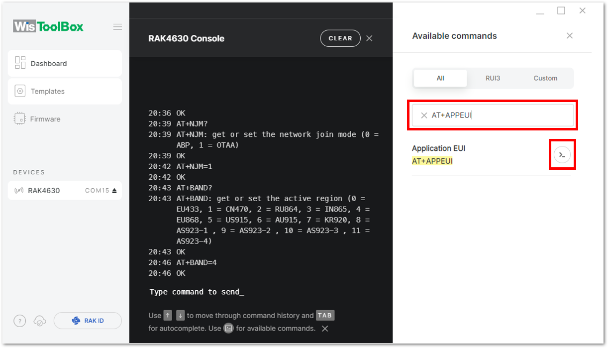 Figure 1: Setting up your Console
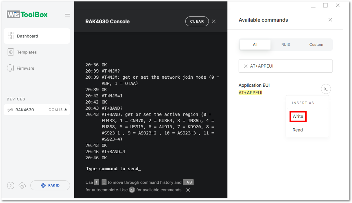 Figure 1: Setting up your Console
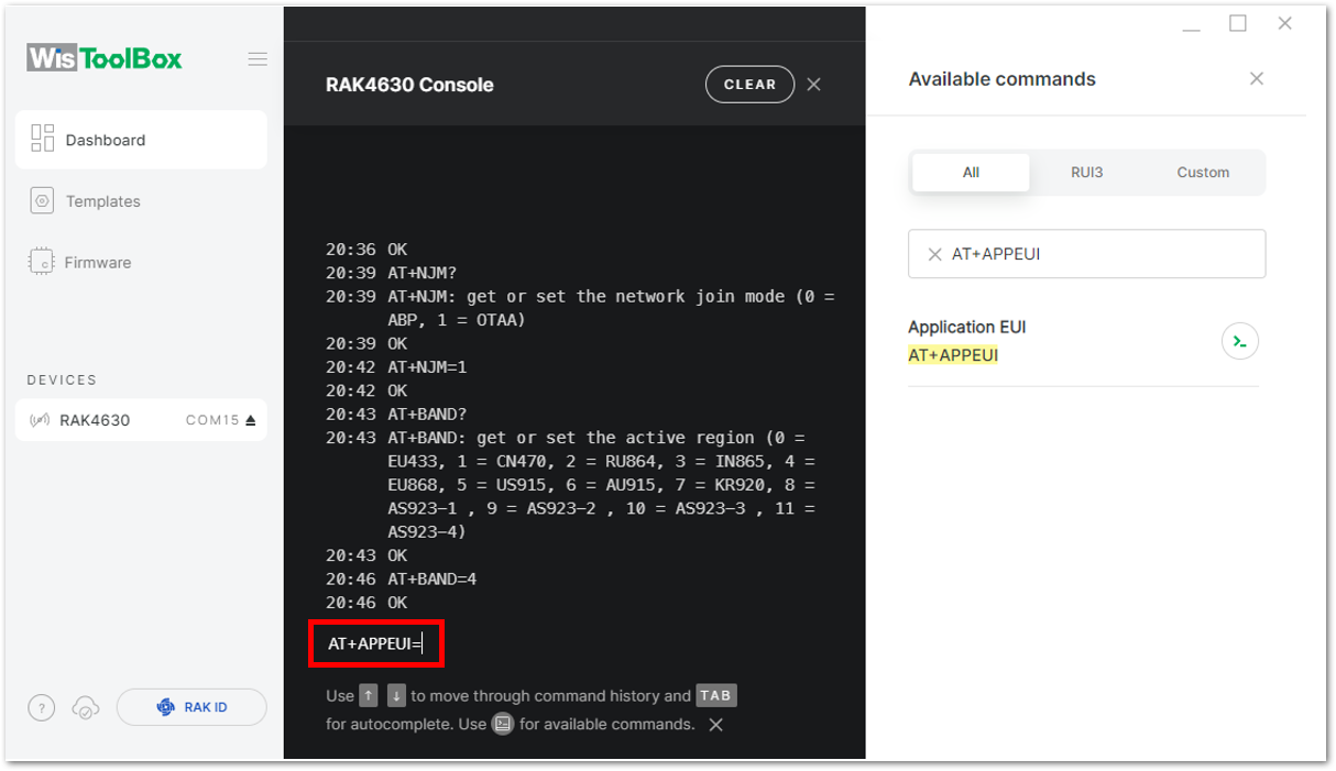 Figure 1: Setting up your Console
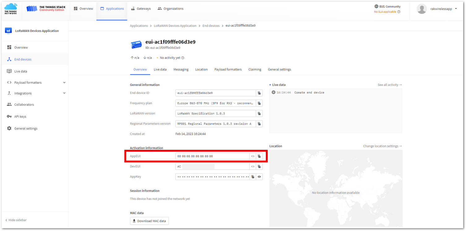 Figure 1: Copying the AppEUI credential from TTN to WisToolBox
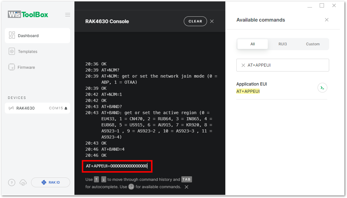 Figure 1: Setting up your Console
- Follow the same procedure for the Application Key (AppKey) and Device EUI (DevEUI). Copy each credential from your console and paste them into the WisToolBox Console, pressing Enter after each one.
- For Application key (AppKey)
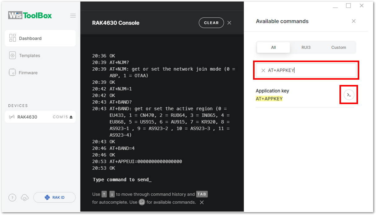 Figure 1: Setting up your Console
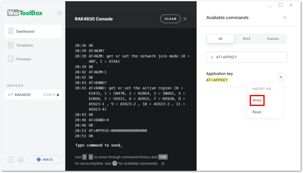 Figure 1: Setting up your Console
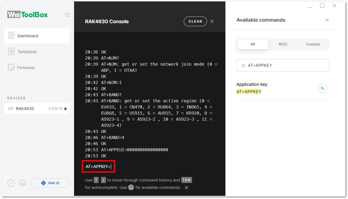 Figure 1: Setting up your Console
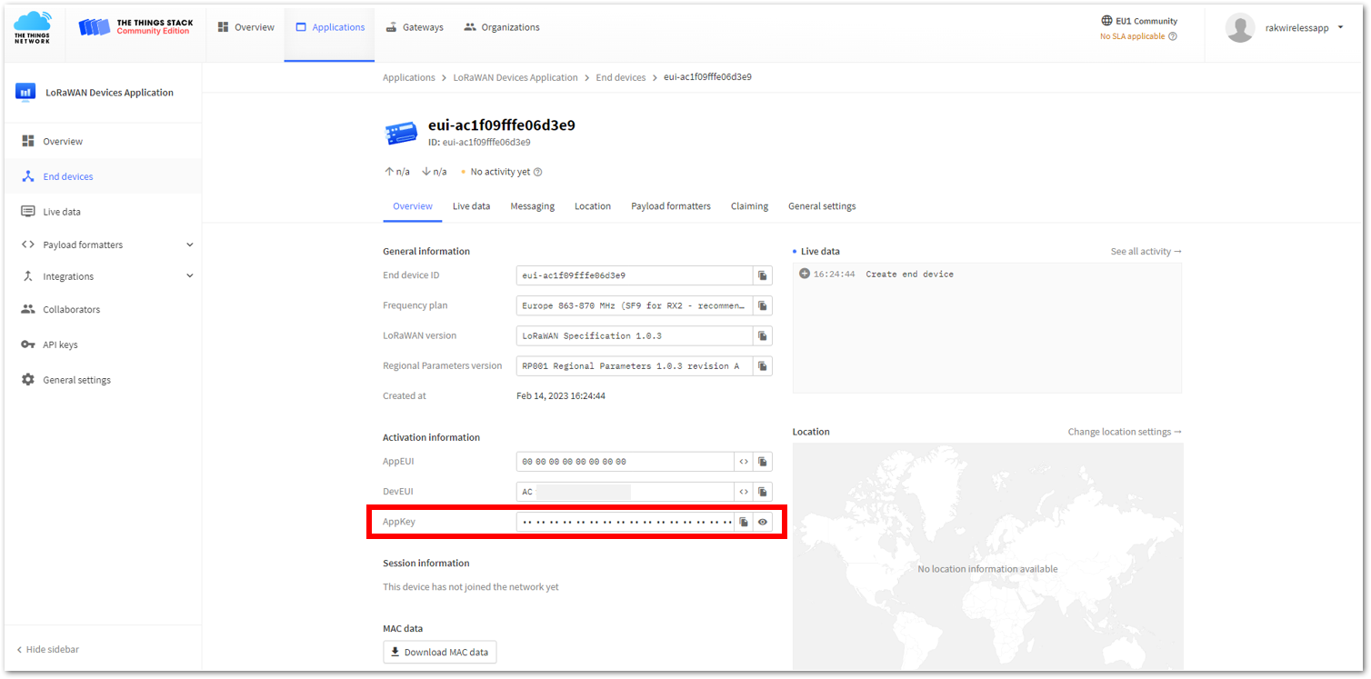 Figure 1: Copying the AppKey credential from TTN to WisToolBox
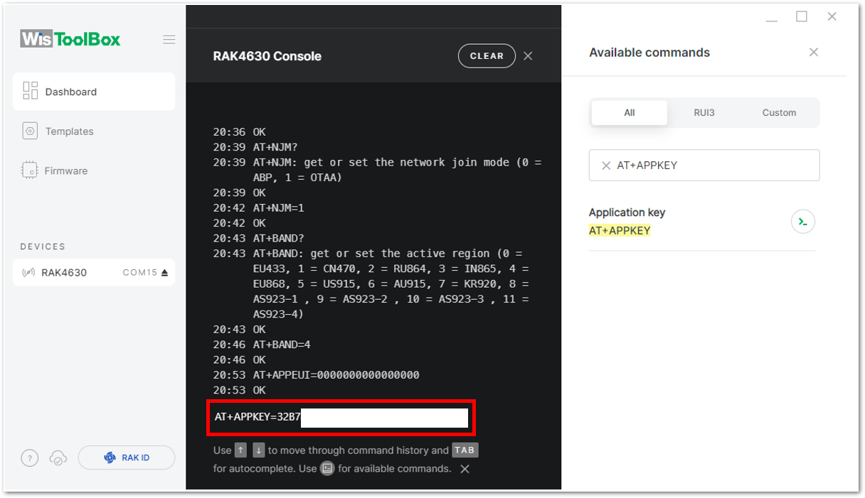 Figure 1: Setting up your Console
- For Device EUI (DevEUI)
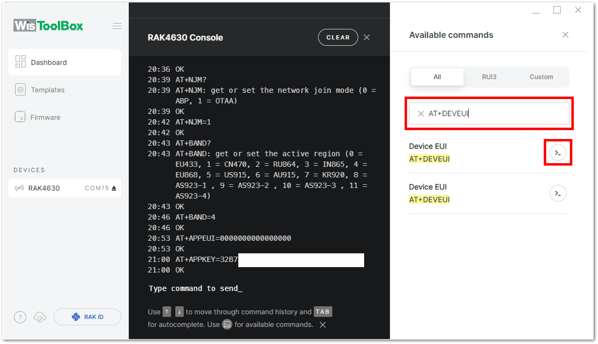 Figure 1: Setting up your Console
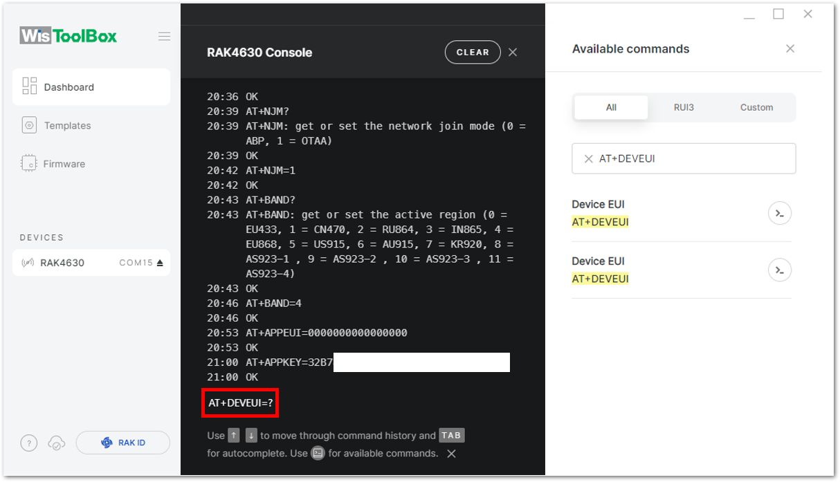 Figure 1: Setting up your Console
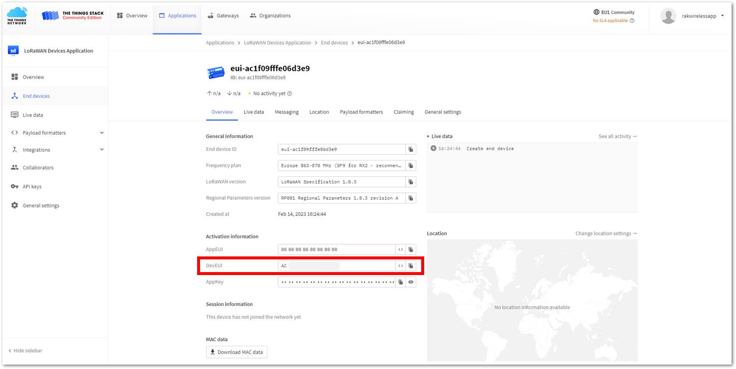 Figure 1: Copying the DevEUI credential from TTN to WisToolBox
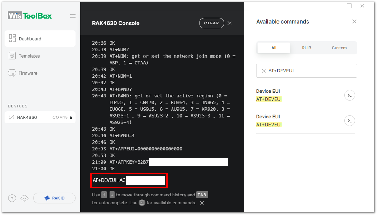 Figure 1: Setting up your Console
- Once done, click Dashboard to check the updated credentials of your OTAA device. Click PARAMETERS to open the Global Settings and LoRaWAN keys, ID, EUI and check whether these portions are updated.
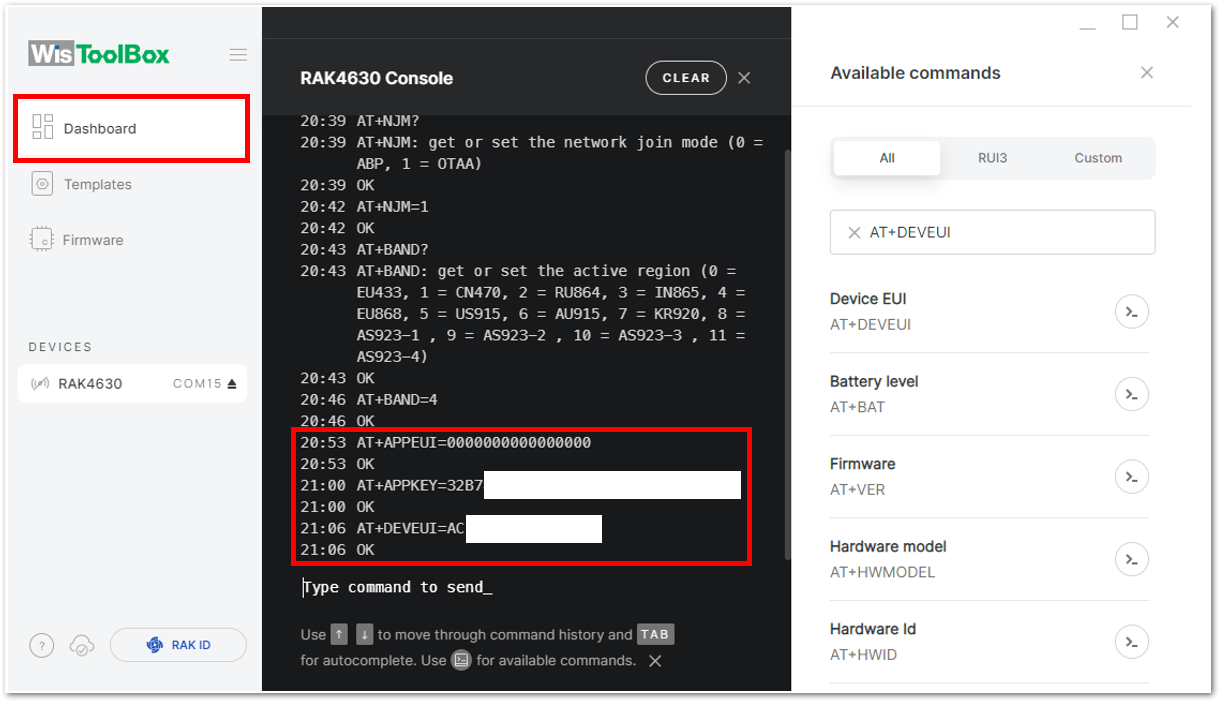 Figure 1: Setting up your Console
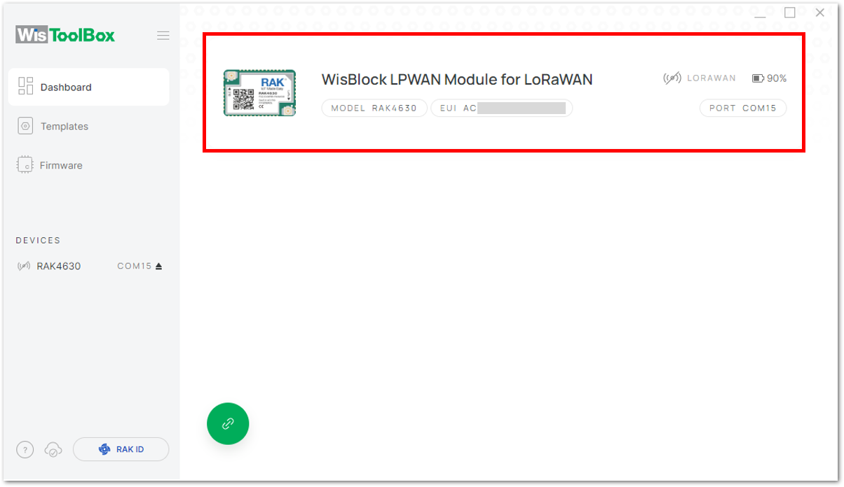 Figure 1: Setting up your Console
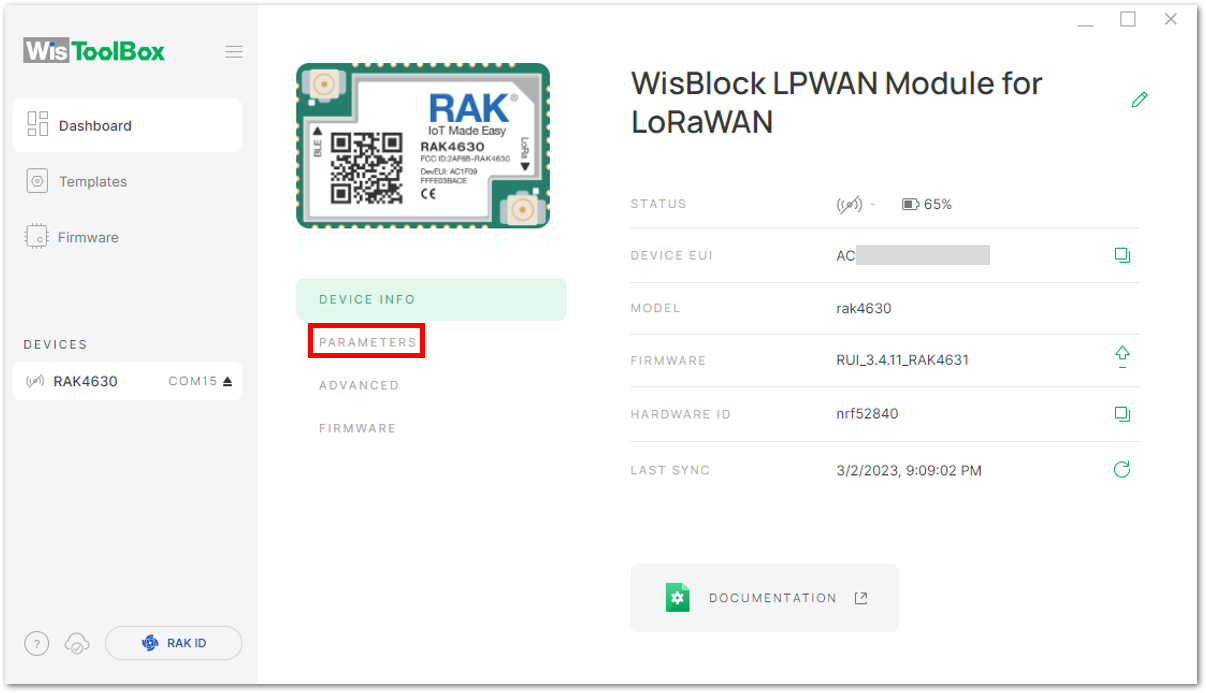 Figure 1: PARAMETERS
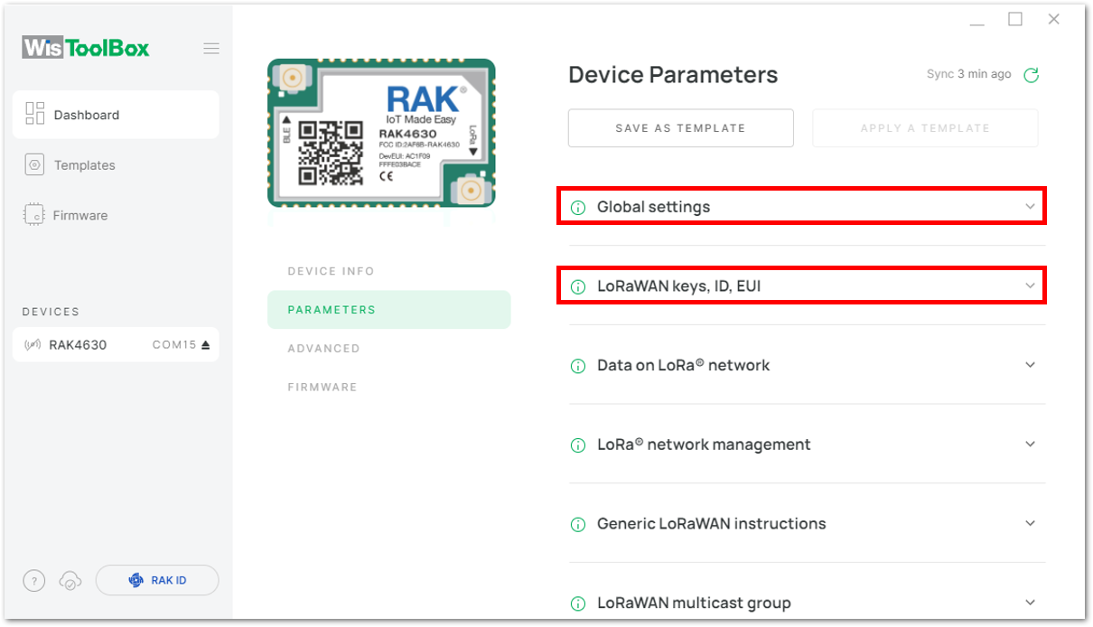 Figure 1: Global settings and LoRaWAN keys, ID, EUI
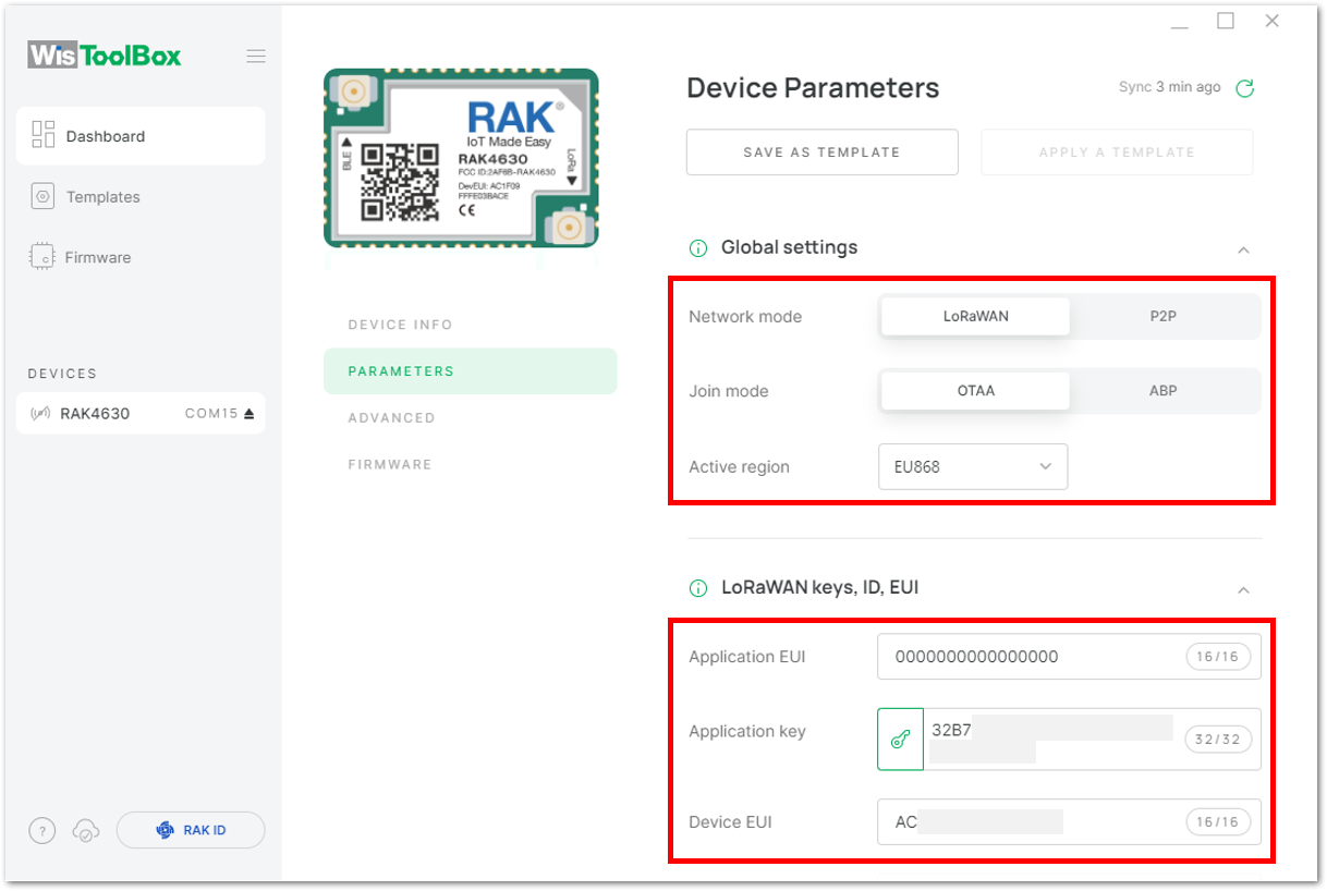 Figure 1: Global settings and LoRaWAN keys, ID, EUI details
Now you have a configured OTAA device using WisToolBox Console. You can now join the network using the WisToolBox console.
- Go back to the WisToolBox console and type
AT+JOIN. Edit it toAT+JOIN=1, then press Enter to join the network.
AT+JOIN command parameters are optional. You can configure the settings for auto-join, reattempt interval, and the number of join attempts if your application needs it. If not configured, it will use the default parameter values.
AT+JOIN and AT+JOIN=1 also share the common functionality of trying to join the network.
Join command format: AT+JOIN=w:x:y:z
| Parameter | Description |
|---|---|
| w | Join command - 1: joining, 0: stop joining. |
| x | Auto-join config - 1: auto-join on power-up, 0: no auto-join |
| y | Reattempt interval in seconds (7-255) - 8 is the default. |
| z | Number of join attempts (0-255) - 0 is the default. |
After 5 or 6 seconds, if the request is successfully received by a LoRa gateway, you should see a +EVT:JOINED status reply.
If the OTAA device failed to join, you need to check if your device is within reach of a working LoRaWAN gateway that is configured to connect to TTN. It is also important to check that all your OTAA parameters (DEVEUI, APPEUI, and APPKEY) are correct using the AT+DEVEUI=?, AT+APPEUI=?, and AT+APPKEY=? commands. Lastly, ensure that the antenna of your device is properly connected.
After checking all the things above, try to join again.
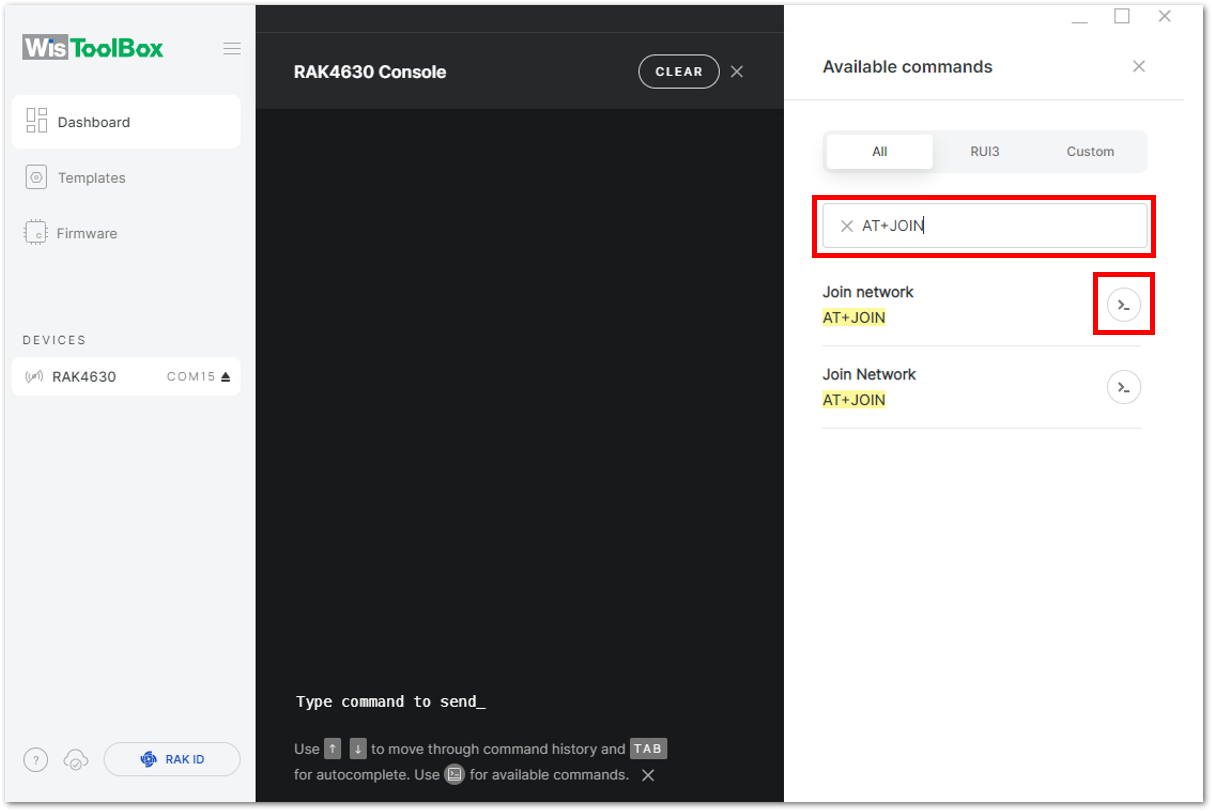 Figure 1: Joining mode using WisToolBox Console
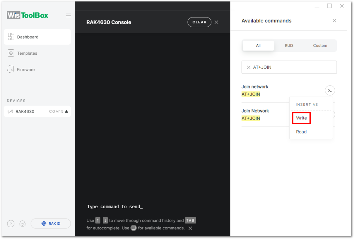 Figure 1: Joining mode using WisToolBox Console
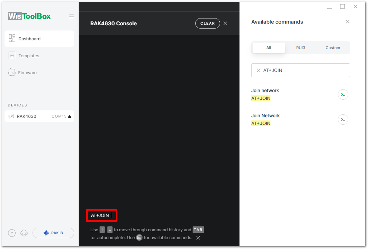 Figure 1: Joining mode using WisToolBox Console
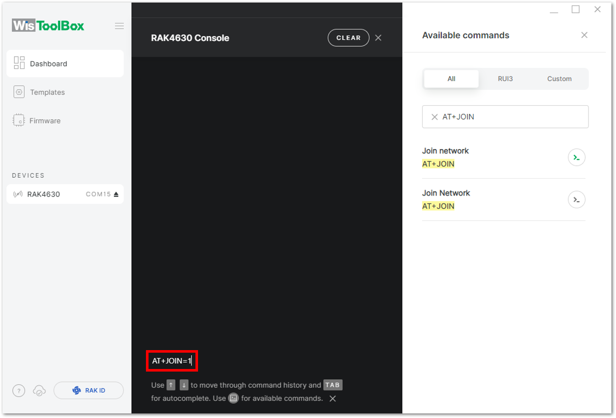 Figure 1: Joining mode using WisToolBox Console
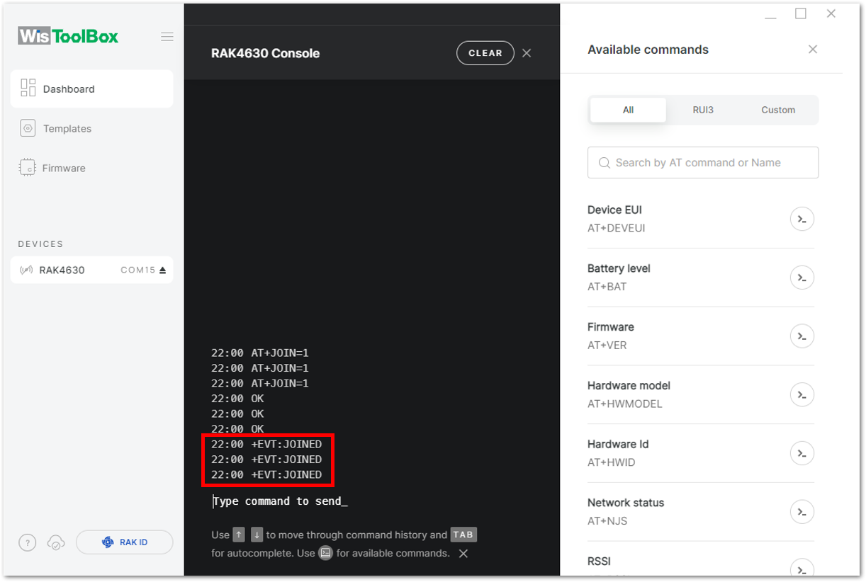 Figure 1: OTAA device successfully joined the network
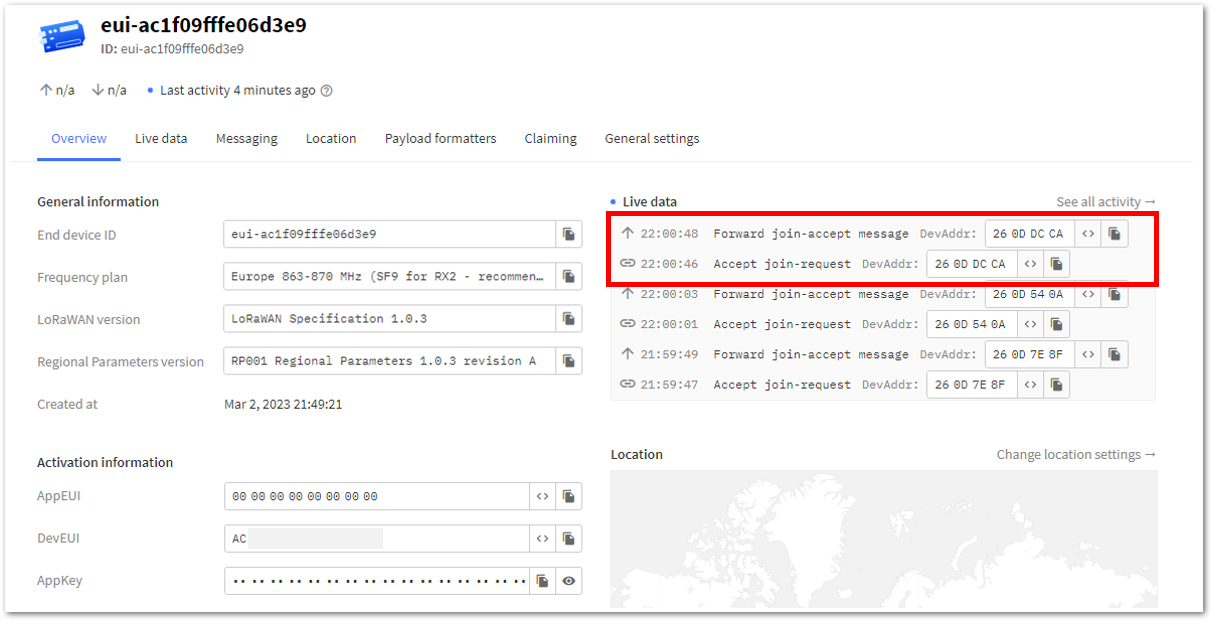 Figure 1: OTAA device successfully joined the network
- With the end-device properly joined to the TTN, try to send some payload after a successful join. Send command format:
AT+SEND=<port>:<payload>
AT+SEND=2:12345678
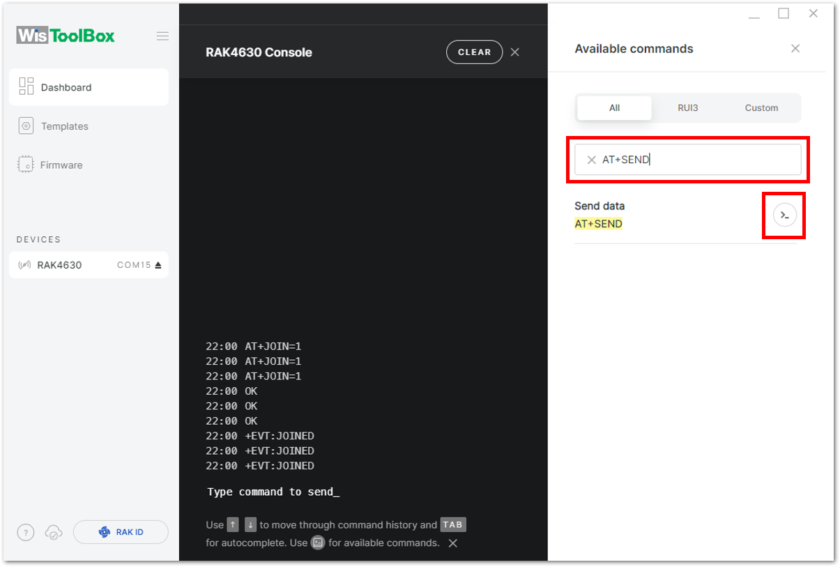 Figure 1: OTAA device sending payload to the network
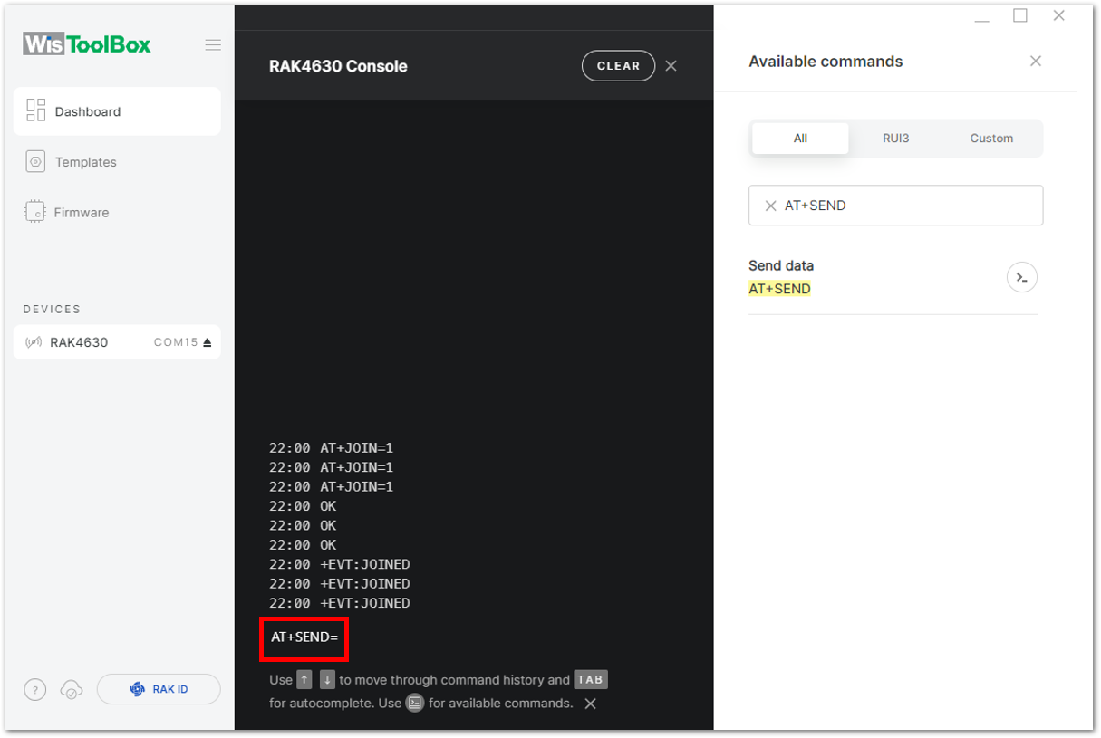 Figure 1: OTAA device sending payload to the network
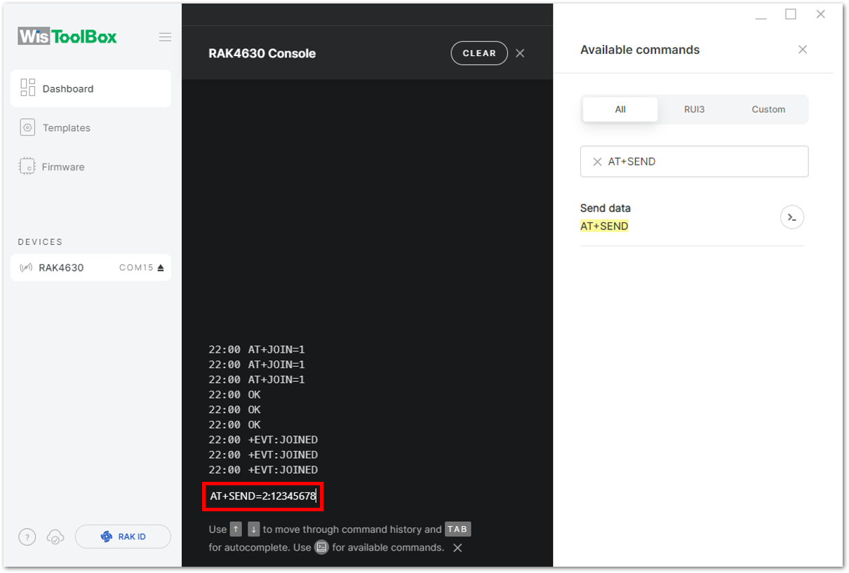 Figure 1: OTAA device sending payload to the network
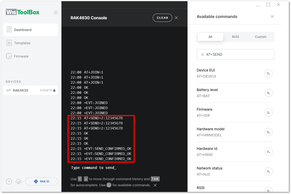 Figure 1: OTAA device sending payload to the network
- You can view the data sent by the RAK4630 module on the TTN device console's Live data section. Additionally, the Last seen information should indicate a few seconds or minutes ago.
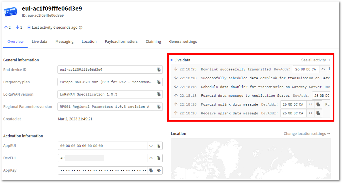 Figure 1: OTAA Test Sample Data Sent Viewed in TTN
TTN ABP Device Registration
- To register an ABP device, navigate to your application console and choose the application to which you want to add your device. Then, click + Register end device, as illustrated in Figure 134.
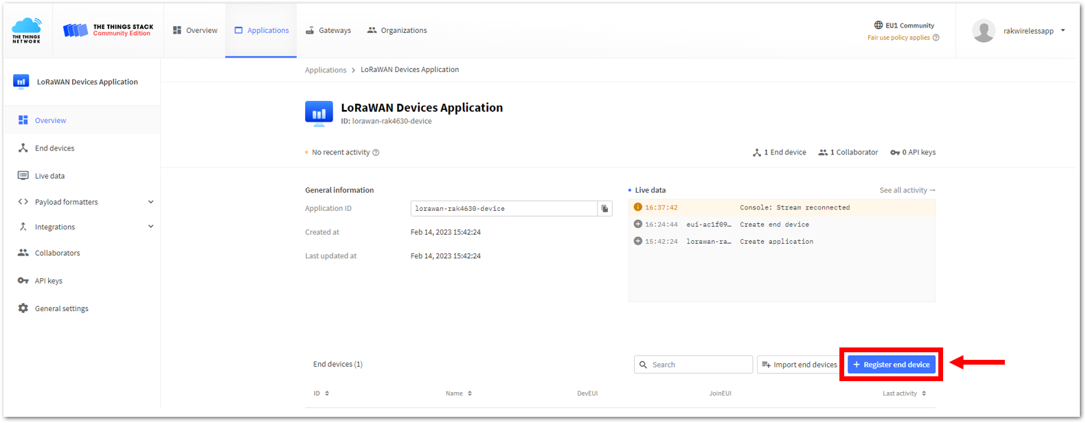 Figure 1: Adding ABP Device
- To register the board, click the Enter end device specifics manually.
 Figure 1: Enter end device specifics manually
- Next, set up the Frequency plan, compatible LoRaWAN version, and Regional Parameters version supported.
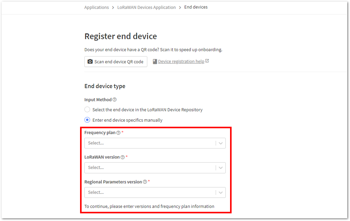 Figure 1: Setting up for your device
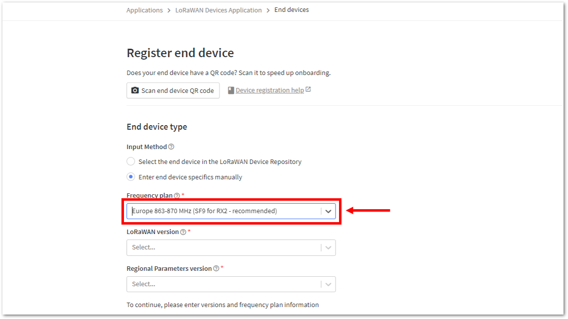 Figure 1: Setting up for your device
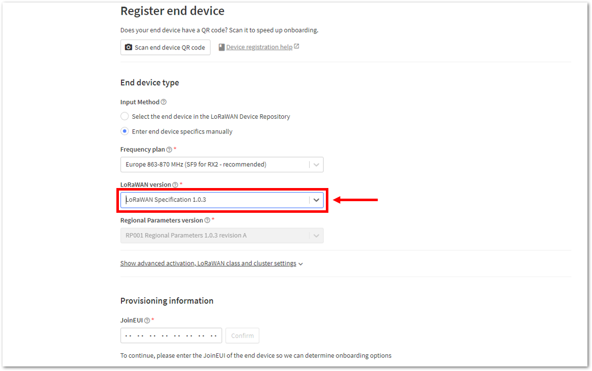 Figure 1: Setting up for your device
- Click Show advanced activation, LoRaWAN class and cluster settings. Configure the activation mode by selecting Activation by personalization (ABP) and Additional LoRaWAN class capabilities to class A only.
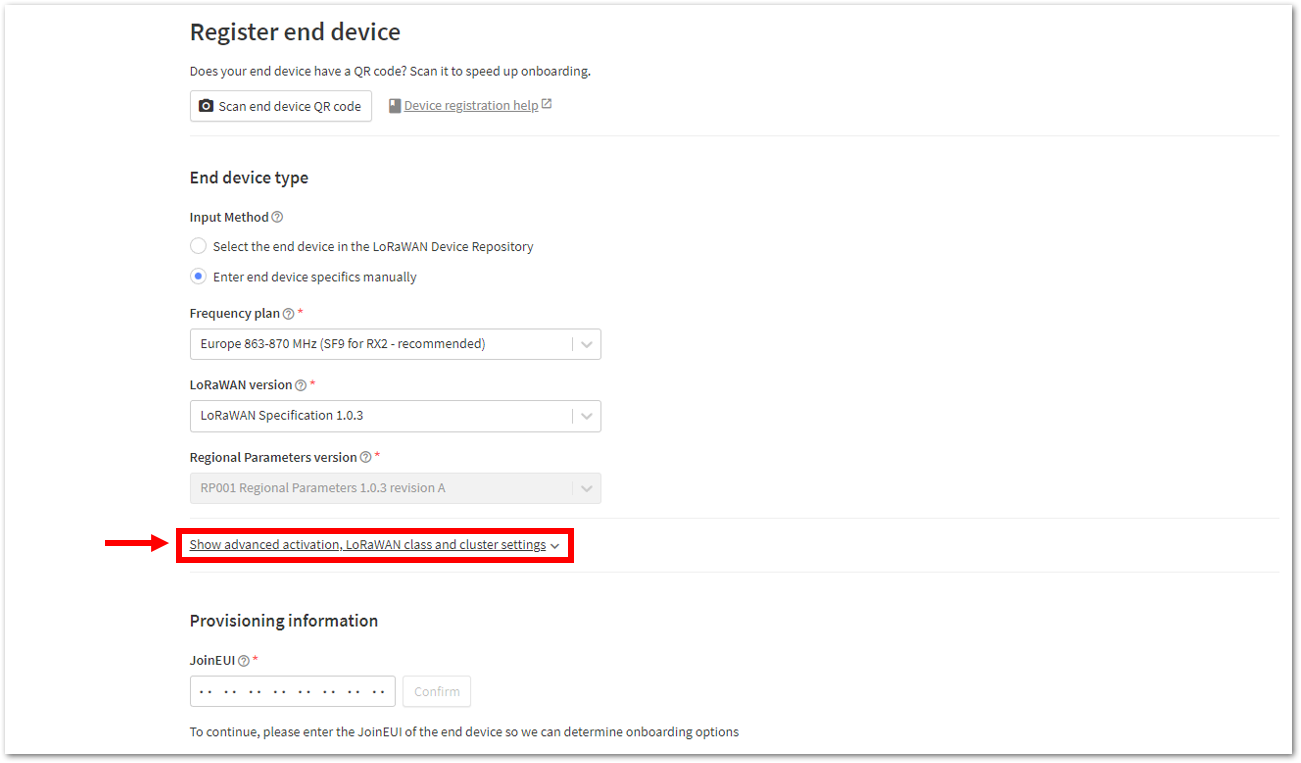 Figure 1: Setting up for your device
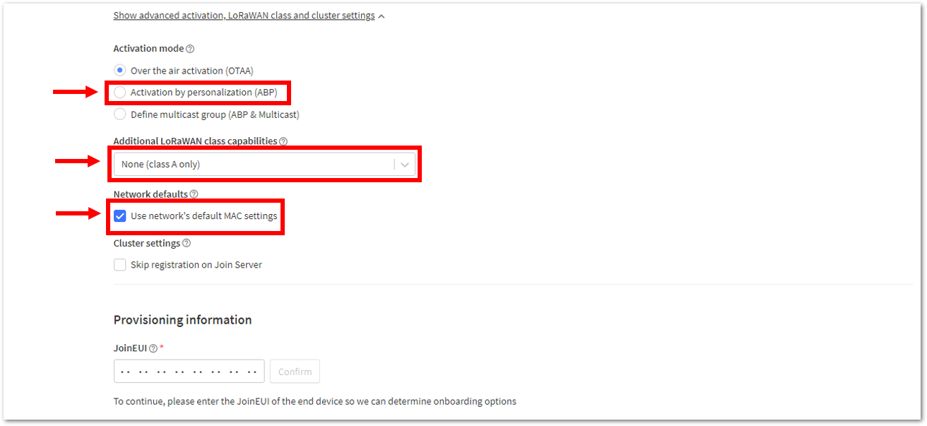 Figure 1: Setting up for your device
- Once completed, enter the DevEUI credentials of your device into the DevEUI field. This will automatically generate the specific End Device ID for your board. Then, click Generate under Device address, AppSKey, and NwkSKey in the Provisioning Information section. Finally, click Register end device.
- The DevEUI, Device address, AppSKey, and NwkSKey are hidden in this section as these are unique from a specific device. The DevEUI credential is unique to every RAK4630 device. Also, you should generate your own Device address, AppSKey, and NwkSKey credentials for your specific device and application.
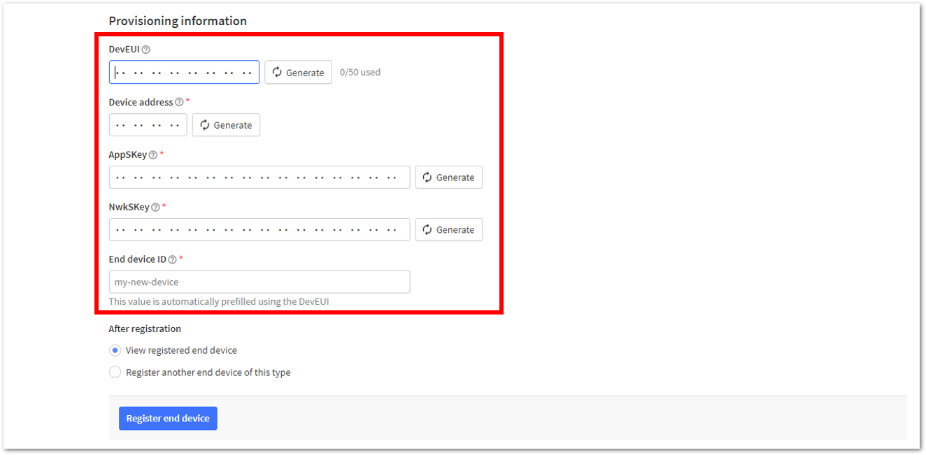 Figure 1: Setting up for your device
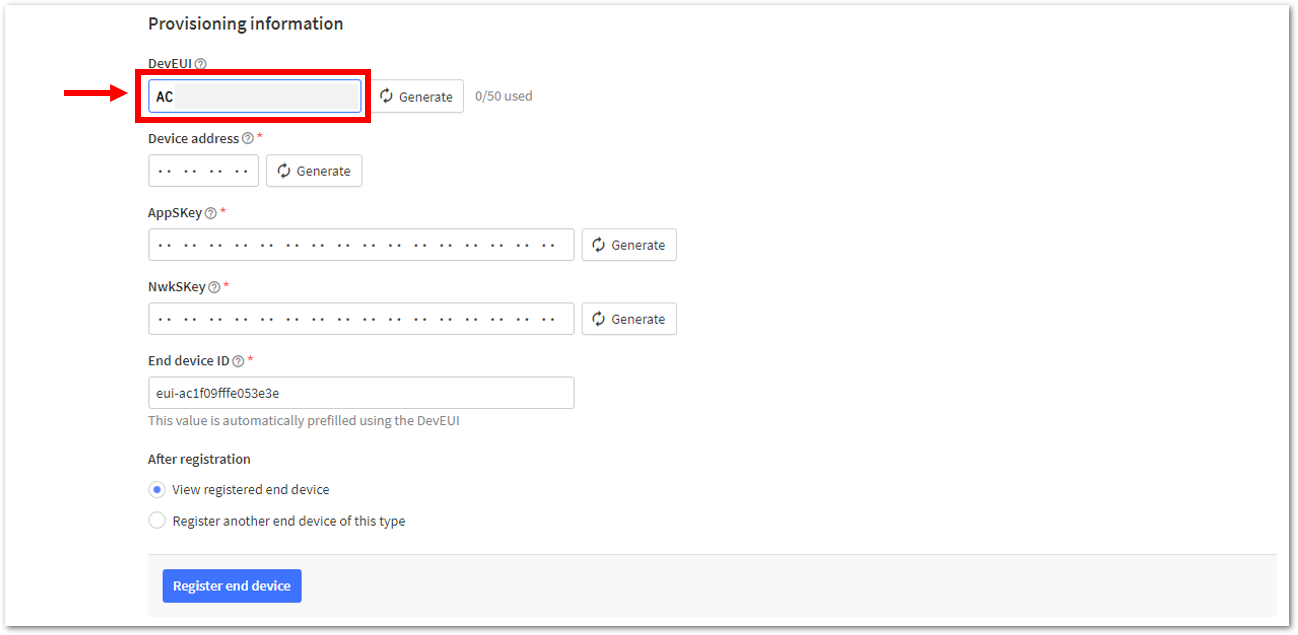 Figure 1: Setting up for your device
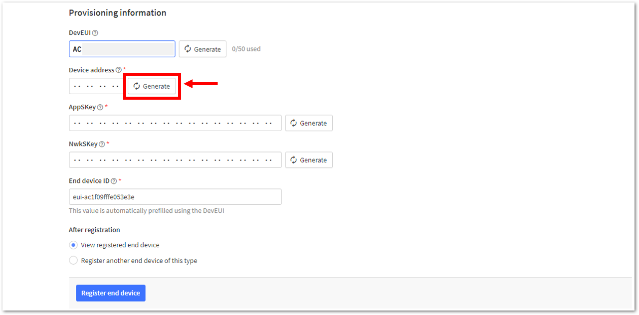 Figure 1: Setting up for your device
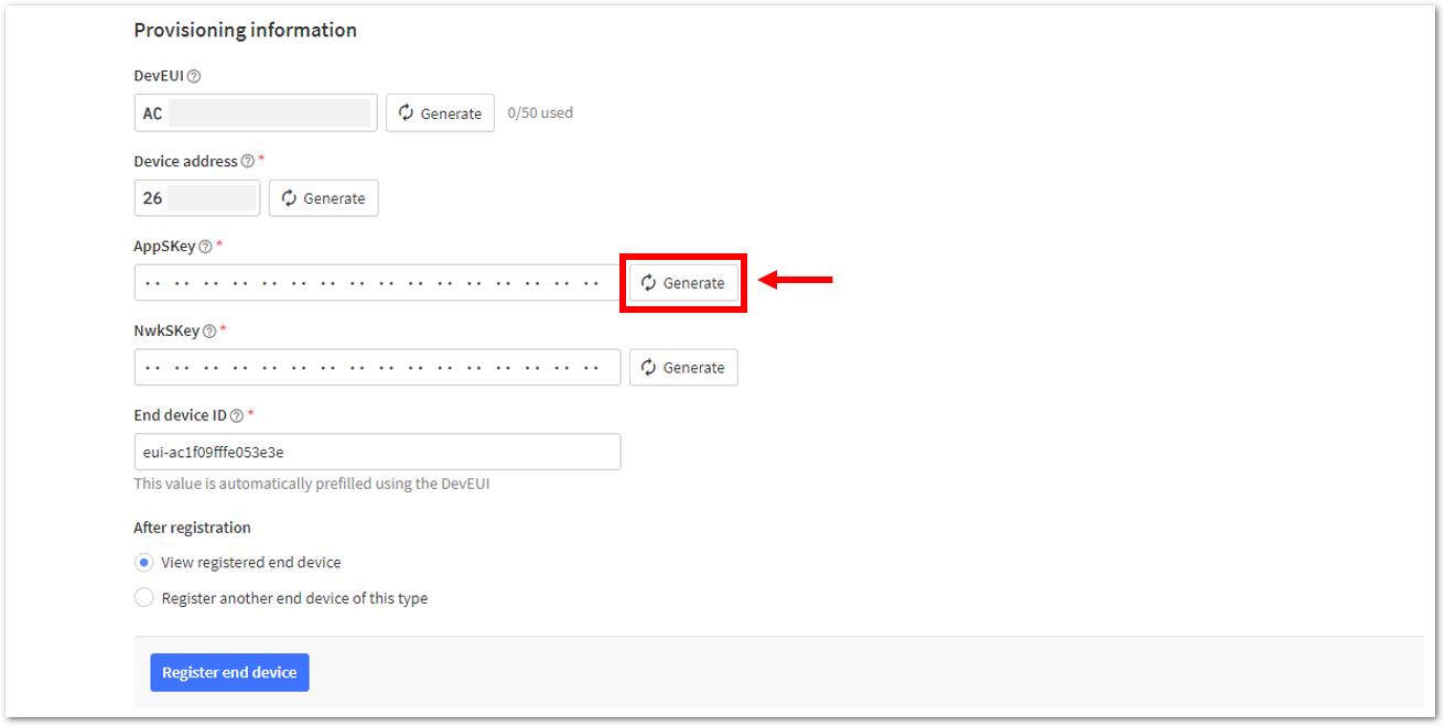 Figure 1: Setting up for your device
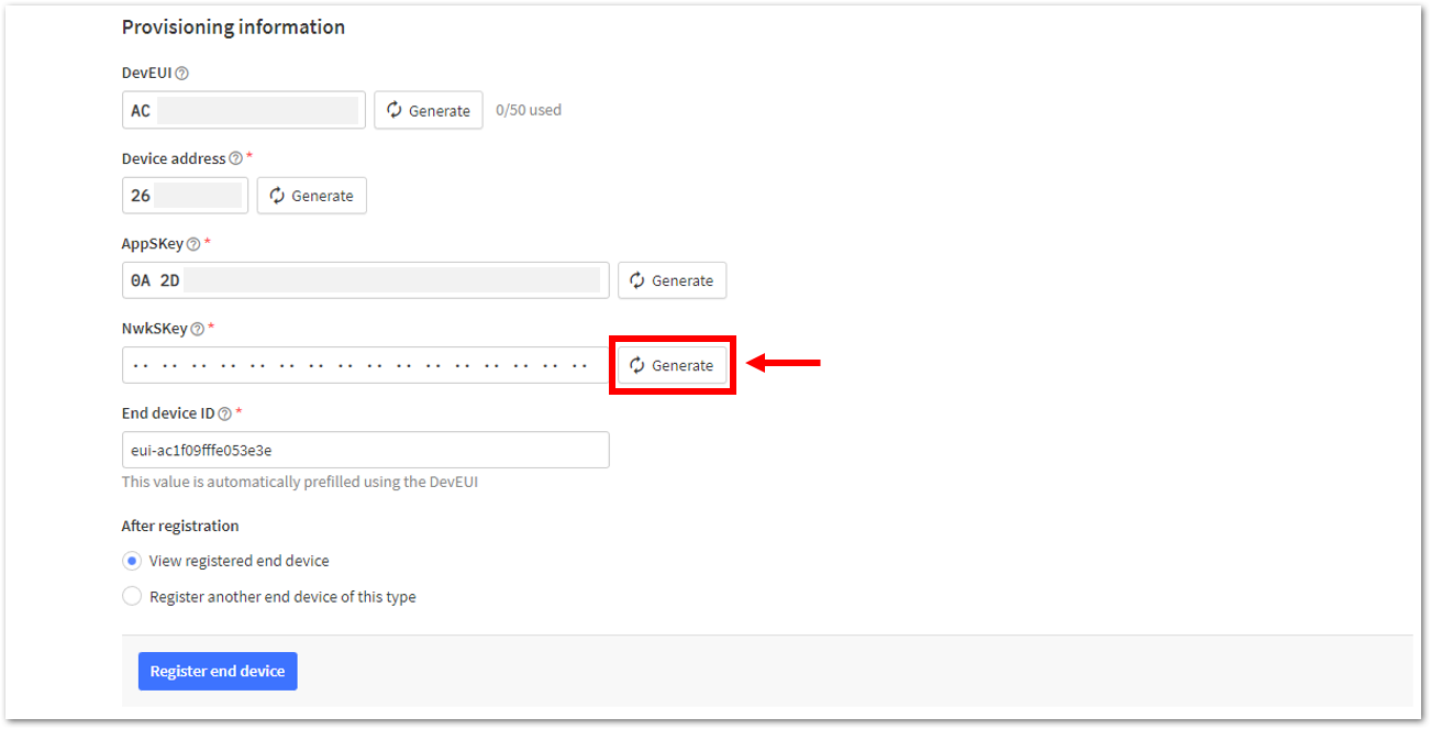 Figure 1: Setting up for your device
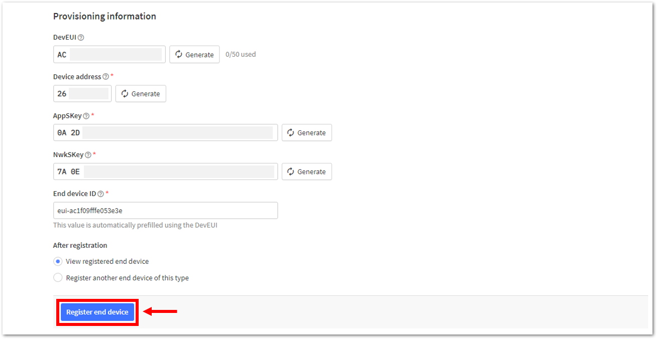 Figure 1: Register end device
- You should now see the device on the TTN console after you fully register your device, as shown in Figure 147.
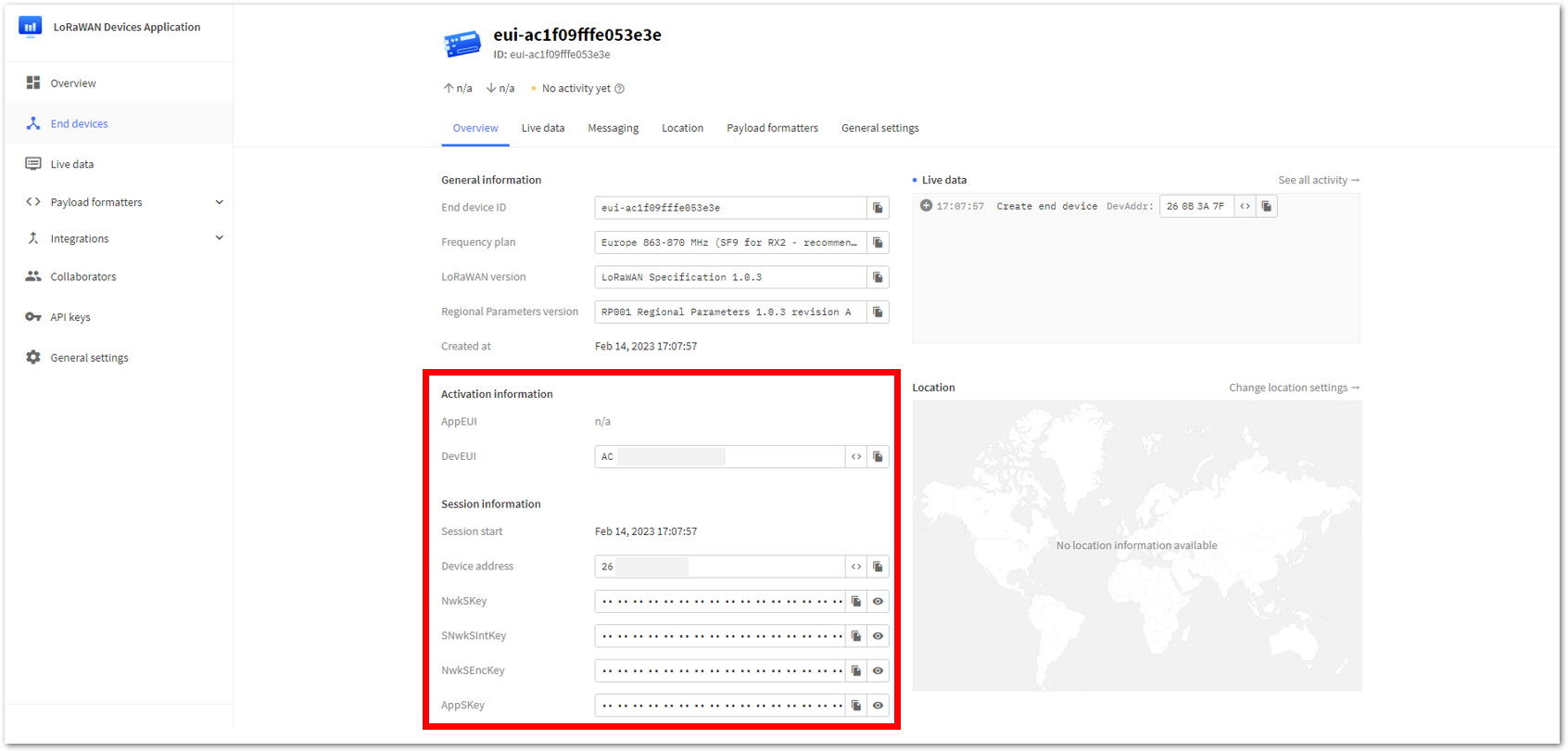 Figure 1: ABP device successfully registered to TTN
ABP Configuration for TTN
The RAK4630 module can be configured using WisToolBox for ABP configuration. WisToolBox is a software tool designed to support the RAK4630 module, automatically detecting the RAK4630 module once connected to the PC. Below are the options available in WisToolBox for ABP configuration:
ABP Configuration for TTN via WisToolBox UI
- Connect your RAK4630 to the PC via USB cable and open the WisToolBox application.
- Click the CONNECT DEVICE button to launch the WisToolBox Dashboard.
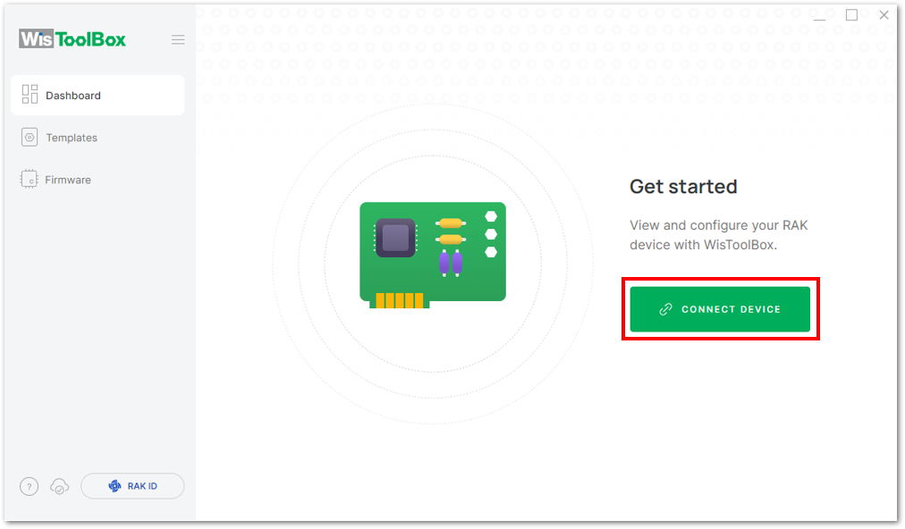 Figure 1: CONNECT DEVICE
- Select your target port where your RAK4630 is connected. Once recognized, click CONNECT as shown in Figure 150.
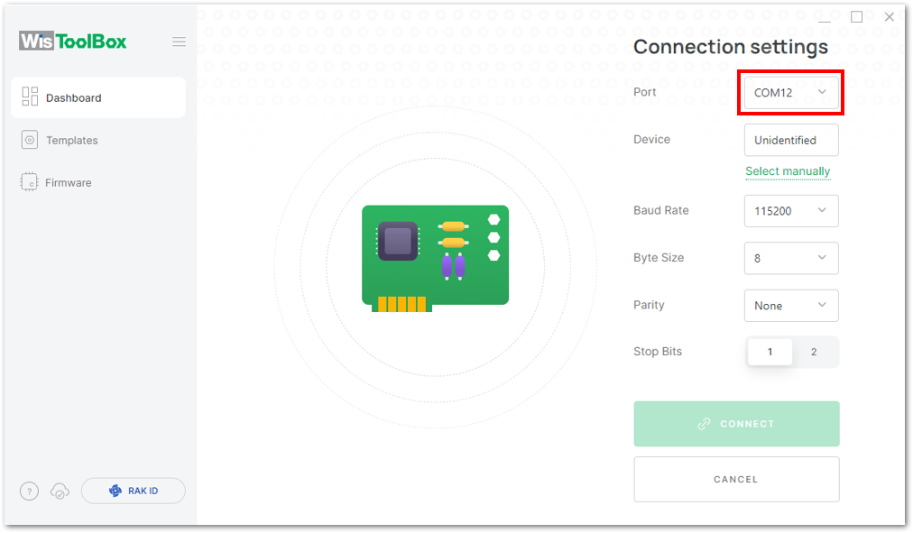 Figure 1: Setting up your device
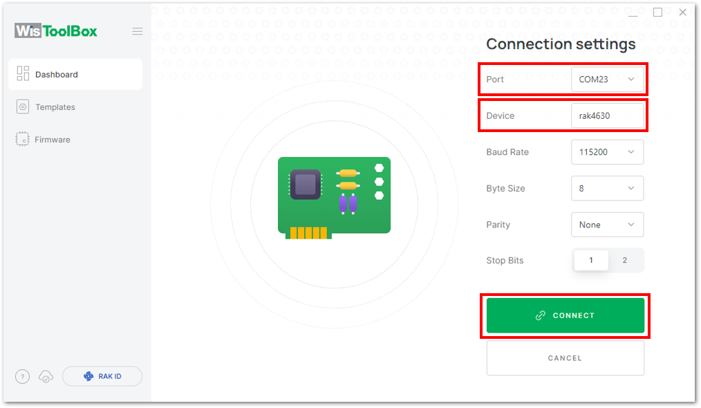 Figure 1: Setting up your device
- The RAK4630 will appear in the dashboard, Click on it.
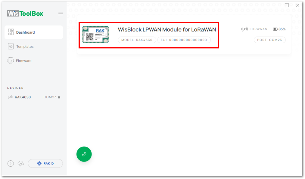 Figure 1: Device seen from WisToolBox dashboard
- Click PARAMETERS to configure the RAK4630.
- The AppSKey, Device address, and NwkSKey are hidden in this section as these are unique from a specific device.
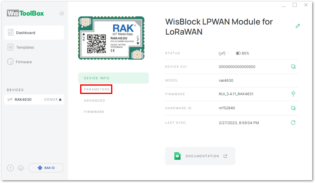 Figure 1: Setting up your device
- Click Global settings to set the network mode to LoRaWAN and the join mode to ABP. Ensure that the active region is set to EU868 for this configuration. If you wish to work on other regional bands, you can choose among the active regions based on your location.
- LoRa network mode: LoRaWAN
- LoRaWAN join mode: ABP
- LoRaWAN region: EU868
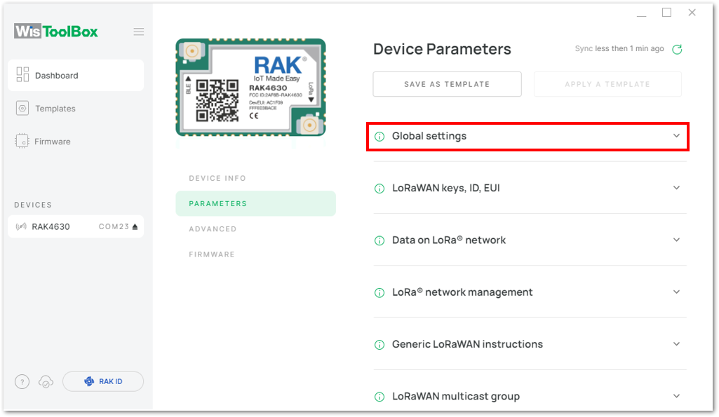 Figure 1: Global settings
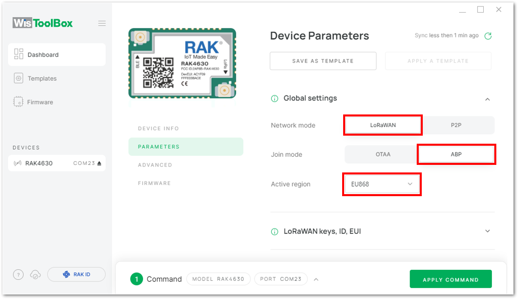 Figure 1: Global settings
- Click LoRaWAN keys, ID, EUI to configure the Application session key (AppSKey), Device address and Network session key (NwkSKey).
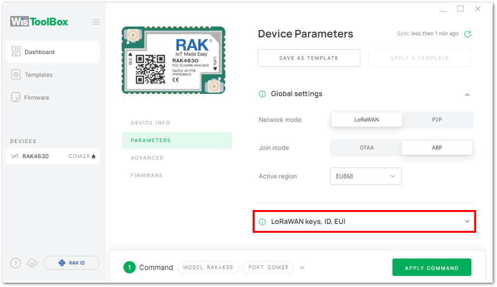 Figure 1: LoRaWAN keys, ID, EUI
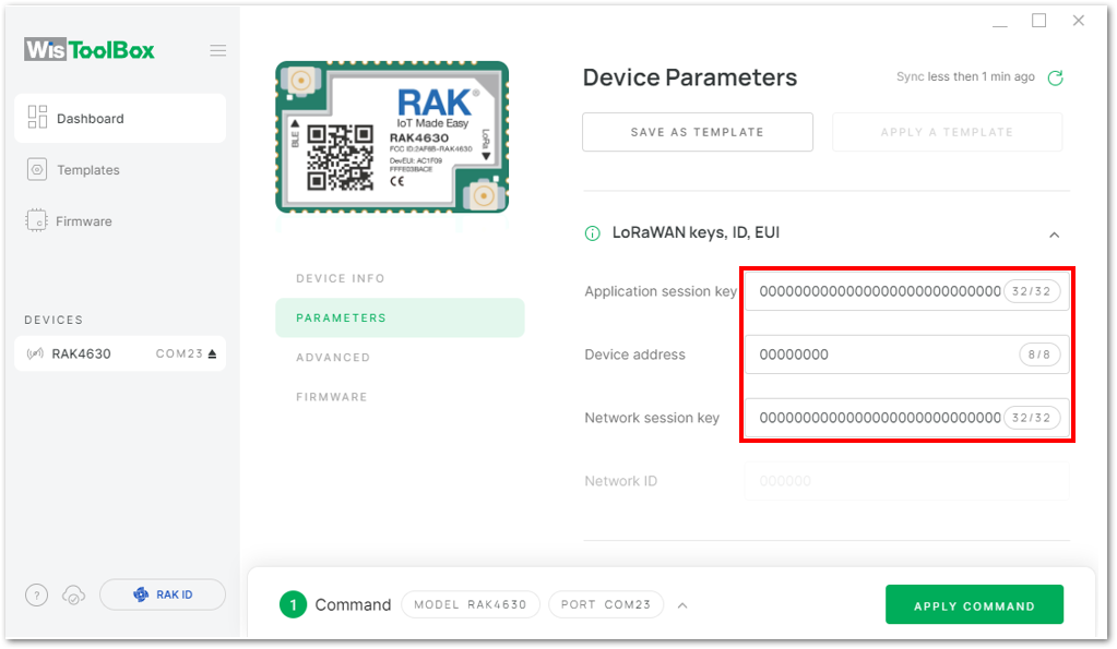 Figure 1: Setting up your device
- Go back to the console where your RAK4630 End device is created previously, then copy all the credentials from there. Those will be the ones to be used also in the WisToolBox dashboard. Once encoded into the dashboard, click APPLY COMMANDS to update your device, as shown in Figure 157.
- The AppSKey, Device address, and NwkSKey are hidden in this section as these are unique from a specific device.
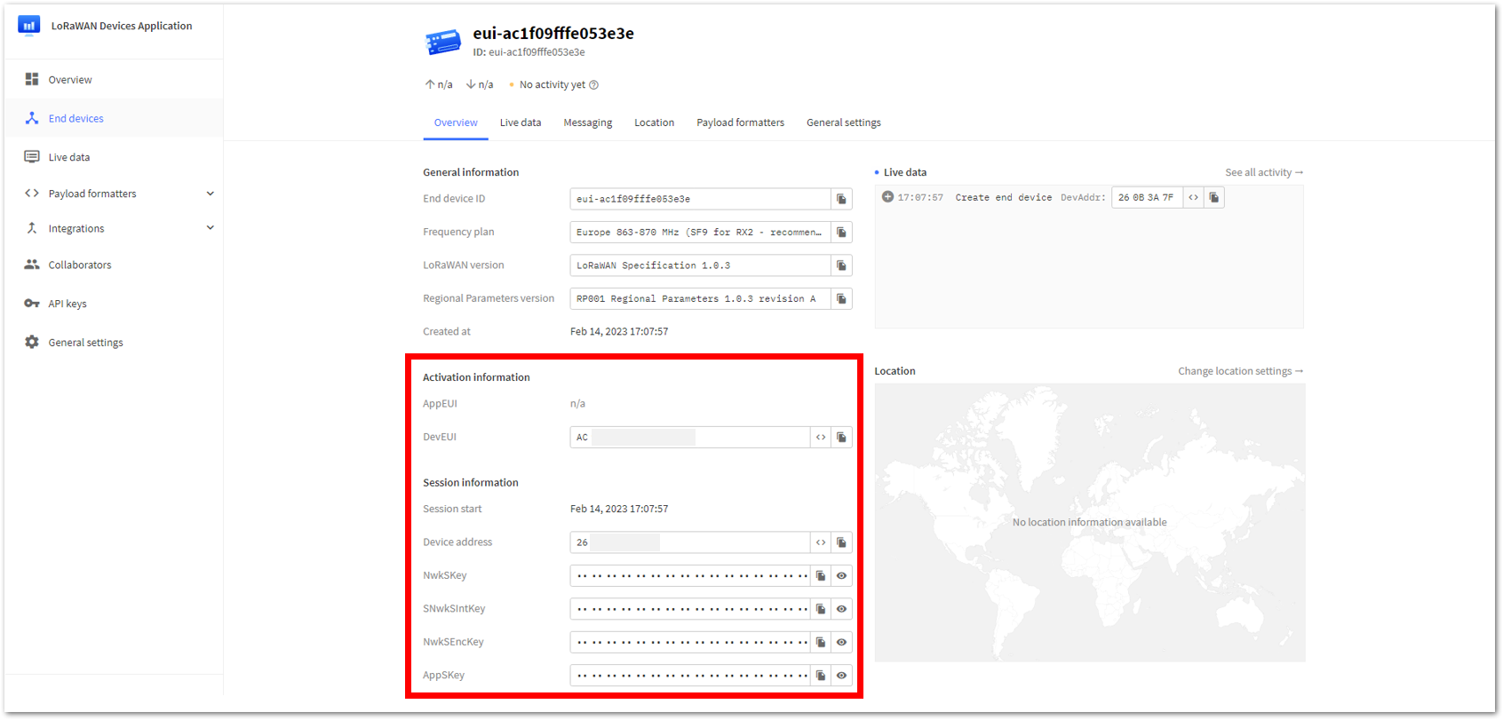 Figure 1: Your created ABP device from your console
- For Application session key (AppSKey)
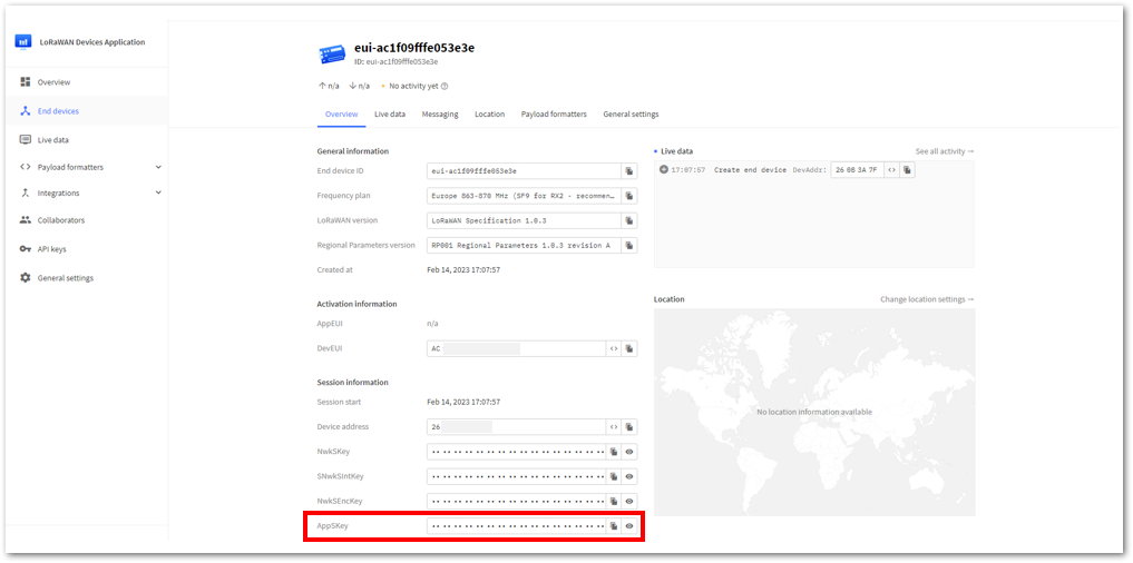 Figure 1: Copying the AppSKey credential from TTN to WisToolBox
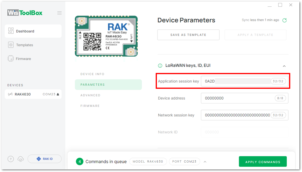 Figure 1: Copying the AppSKey credential from TTN to WisToolBox
- For Device address
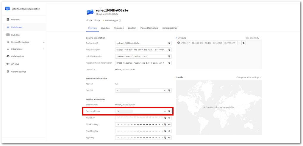 Figure 1: Copying the Device address credential from TTN to WisToolBox
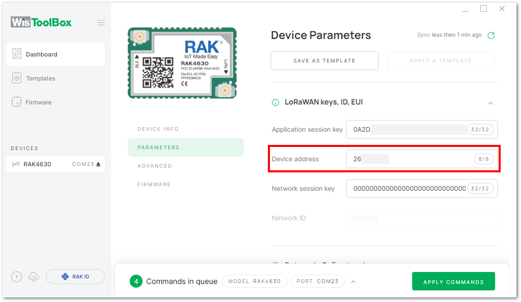 Figure 1: Copying the Device address credential from TTN to WisToolBox
- For Network session key (NwkSKey)
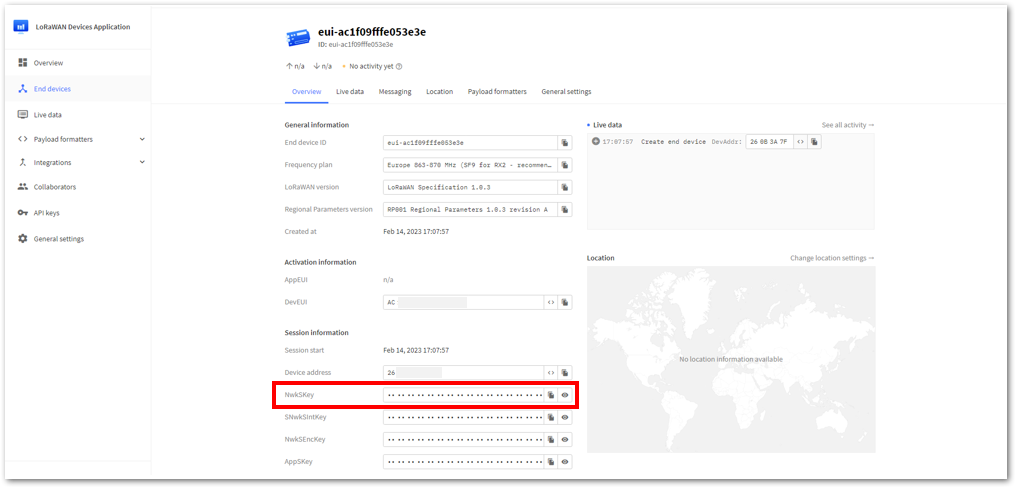 Figure 1: Copying the NwkSKey credential from TTN to WisToolBox
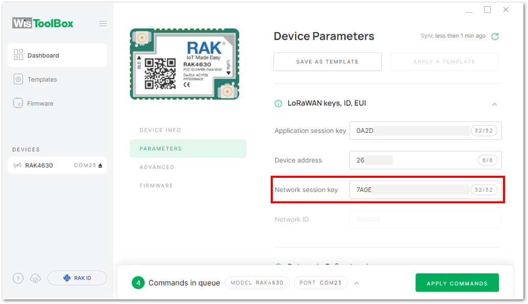 Figure 1: Copying the NwkSKey credential from TTN to WisToolBox
- WisToolBox Dashboard
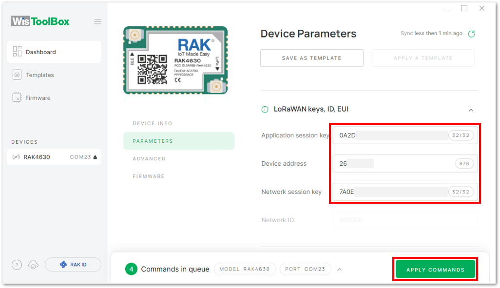 Figure 1: Used credentials from your console in WisToolBox dashboard
- Once completed, you will see a summary of the commands that were applied to your device. Then, click CLOSE.
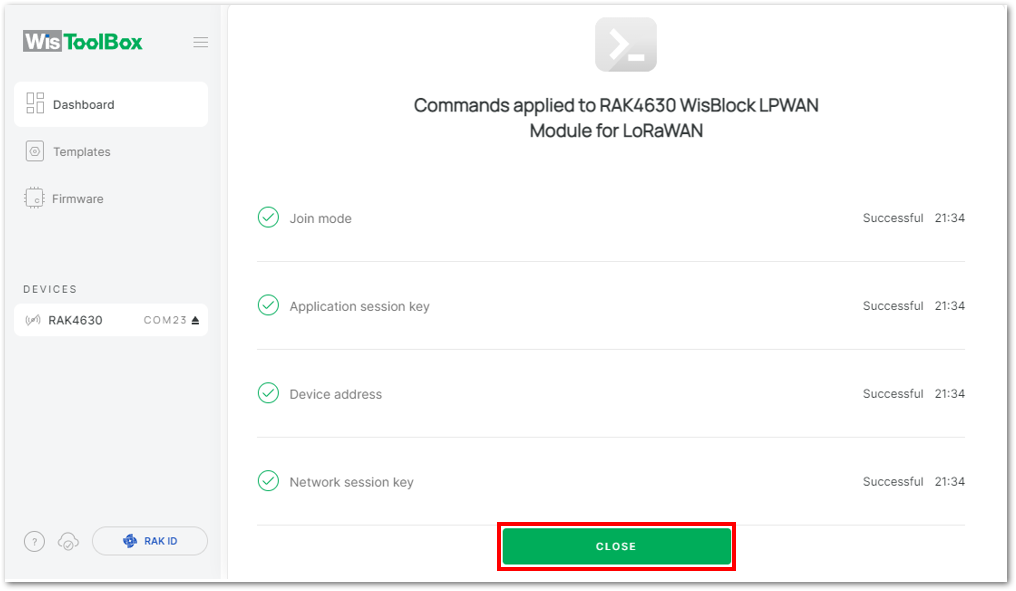 Figure 1: Summary of commands
- Now you will see it returns to the dashboard with updated credentials of your device.
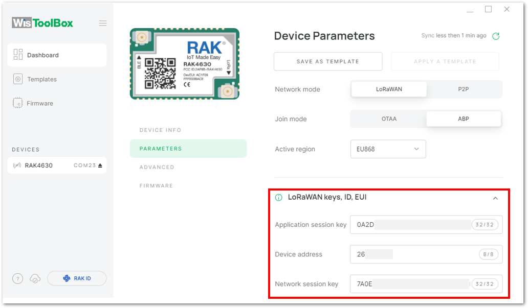 Figure 1: Successfully configured ABP device via WisToolBox dashboard
ABP Configuration for TTN via WisToolBox Console
Here's another way of ABP configuration using WisToolBox Console. Below are the steps on setting up your RAK4630 using WisToolBox Console.
- Connect your RAK4630 to the PC via USB cable and open the WisToolBox application.
- Click the CONNECT DEVICE button to launch the WisToolBox Dashboard.
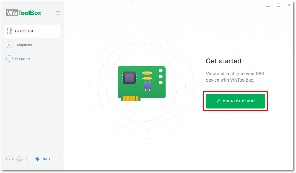 Figure 1: CONNECT DEVICE
- Select your target port where your RAK4630 is connected. Once recognized, click CONNECT as shown in Figure 169.
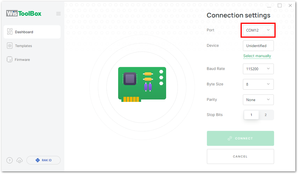 Figure 1: Setting up your device
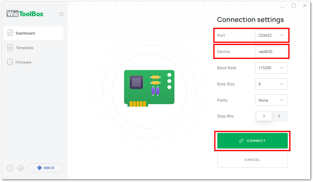 Figure 1: Setting up your device
- Once done, the RAK4630 will appear in the dashboard, click on it.
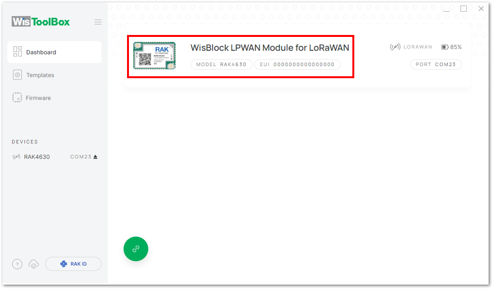 Figure 1: Device seen from WisToolBox dashboard
- Click ADVANCED.
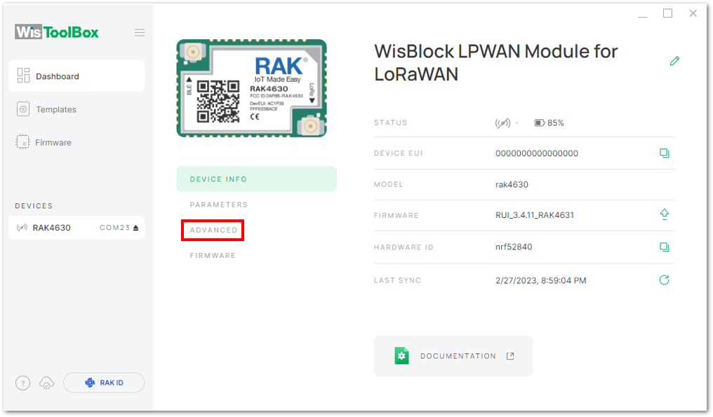 Figure 1: Setting up your device
- click OPEN CONSOLE to proceed with the configuration.
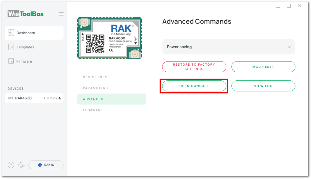 Figure 1: OPEN CONSOLE
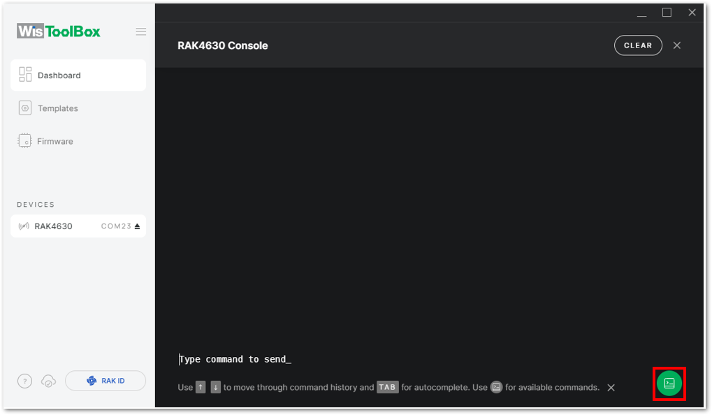 Figure 1: Opening the Console terminal of WisToolBox
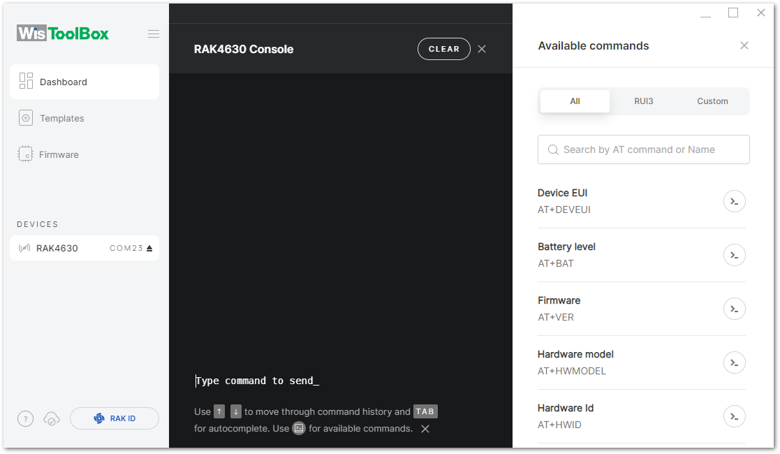 Figure 1: Opening the Console terminal of WisToolBox
- To start the configuration, type ATE so you can echo the commands you input during your configuration. Then press Enter.
It is recommended to start by testing the console and verify that the current configuration is working by sending these two AT commands:
AT
ATE
ATE is useful for tracking the commands and troubleshooting.
You will receive OK when you input the two commands. After setting ATE, see all the commands you input together with the replies.
If there is no OK or any reply, check if the device is powered correctly. If you are getting power from a USB port, ensure that you have a good USB cable.
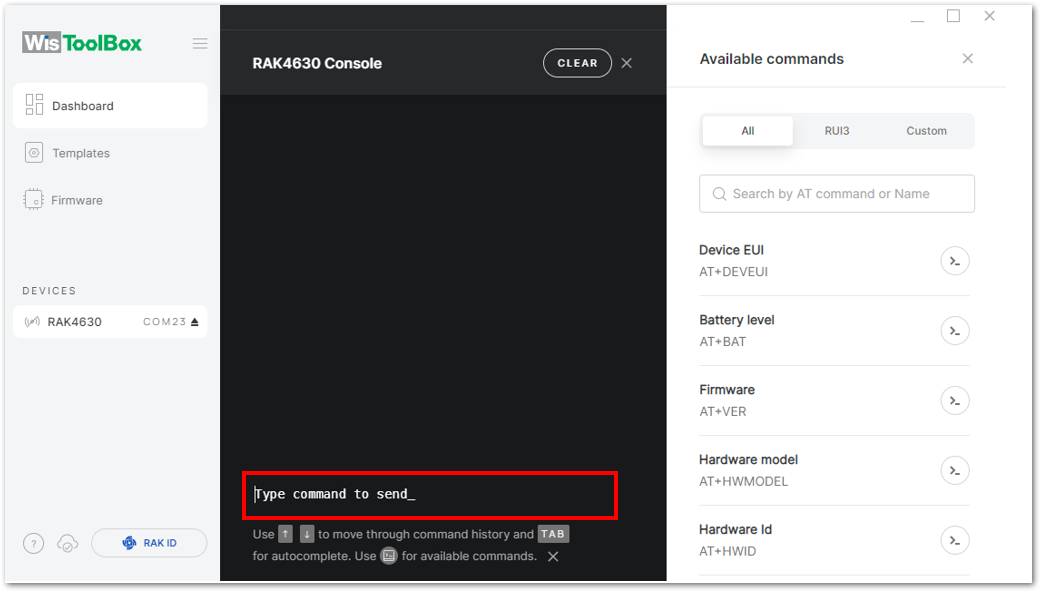 Figure 1: Setting up your Console
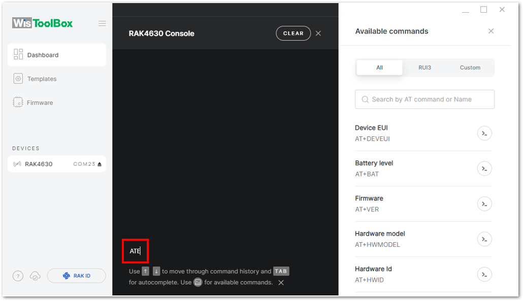 Figure 1: Setting up your Console
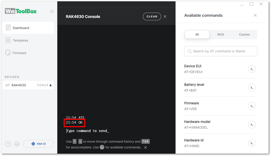 Figure 1: Setting up your Console
- Configure the LoRaWAN join mode to ABP. Check what parameter you will input by typing
AT+NJM?and then Enter into the console terminal. For ABP, inputAT+NJM=0and then press Enter as shown in Figure 180.
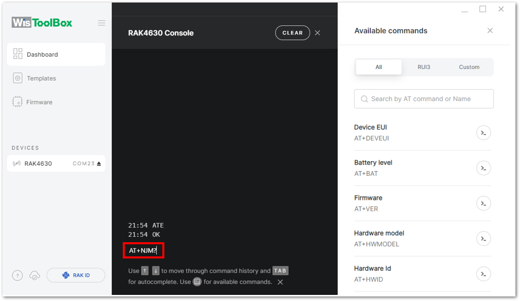 Figure 1: Setting up your Console
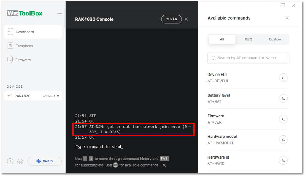 Figure 1: Setting up your Console
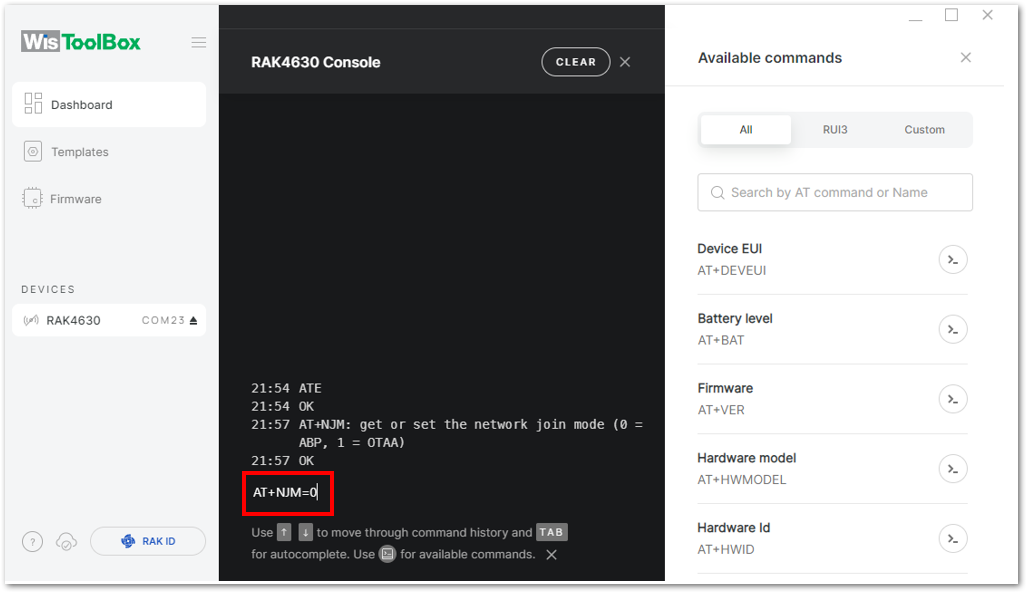 Figure 1: Setting up your Console
- Once done, set up your LoRaWAN region to EU868. Check what parameter you will input by typing AT+BAND? and then Enter into the console terminal. For EU868, input AT+BAND=4 then press Enter. If you wish to work on other regional bands, you may check the List of band parameter options
Set the frequency/region to EU868.
AT+BAND=4
Depending on the Regional Band you selected, you might need to configure the sub-band of your RAK4630 to match the gateway and LoRaWAN network server. This is especially important for Regional Bands like US915, AU915, and CN470.
To configure the masking of channels for the sub-bands, you can use the AT+MASK command that can be found on the AT Command Manual.
To illustrate, you can use sub-band 2 by sending the command AT+MASK=0002.
List of band parameter options
| Code | Regional Band |
|---|---|
| 0 | EU433 |
| 1 | CN470 |
| 2 | RU864 |
| 3 | IN865 |
| 4 | EU868 |
| 5 | US915 |
| 6 | AU915 |
| 7 | KR920 |
| 8 | AS923-1 |
| 9 | AS923-2 |
| 10 | AS923-3 |
| 11 | AS923-4 |
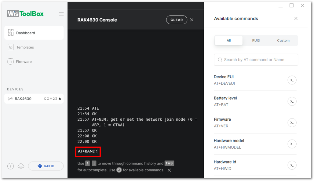 Figure 1: Setting up your Console
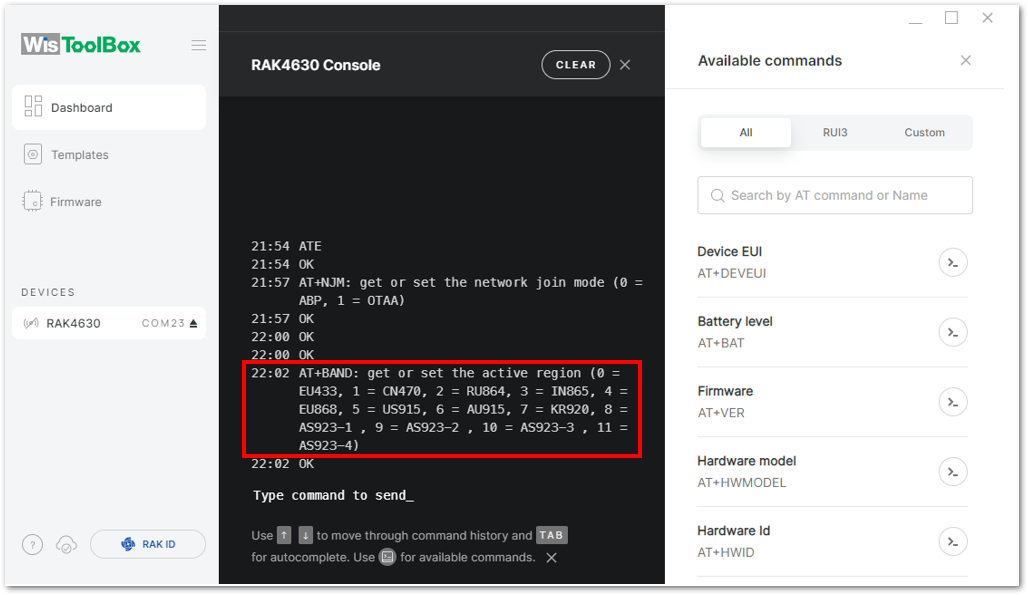 Figure 1: Setting up your Console
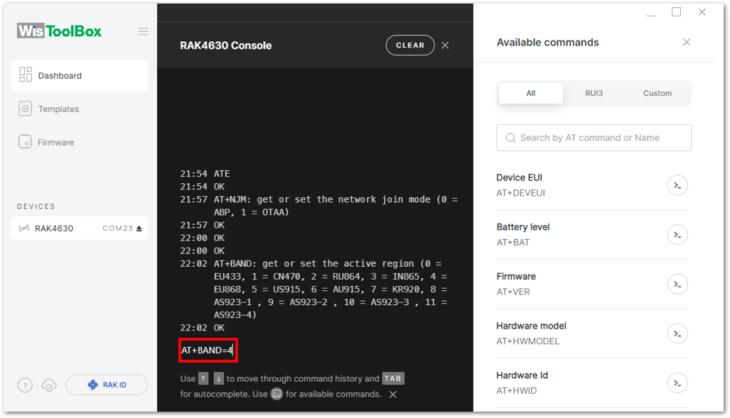 Figure 1: Setting up your Console
- Update the ABP credentials of your device and start with the Application Session Key (AppSKey). Go back to your console where your RAK4630 End device was created to copy the AppSKey credential, then paste it into the WisToolBox Console, and press Enter.
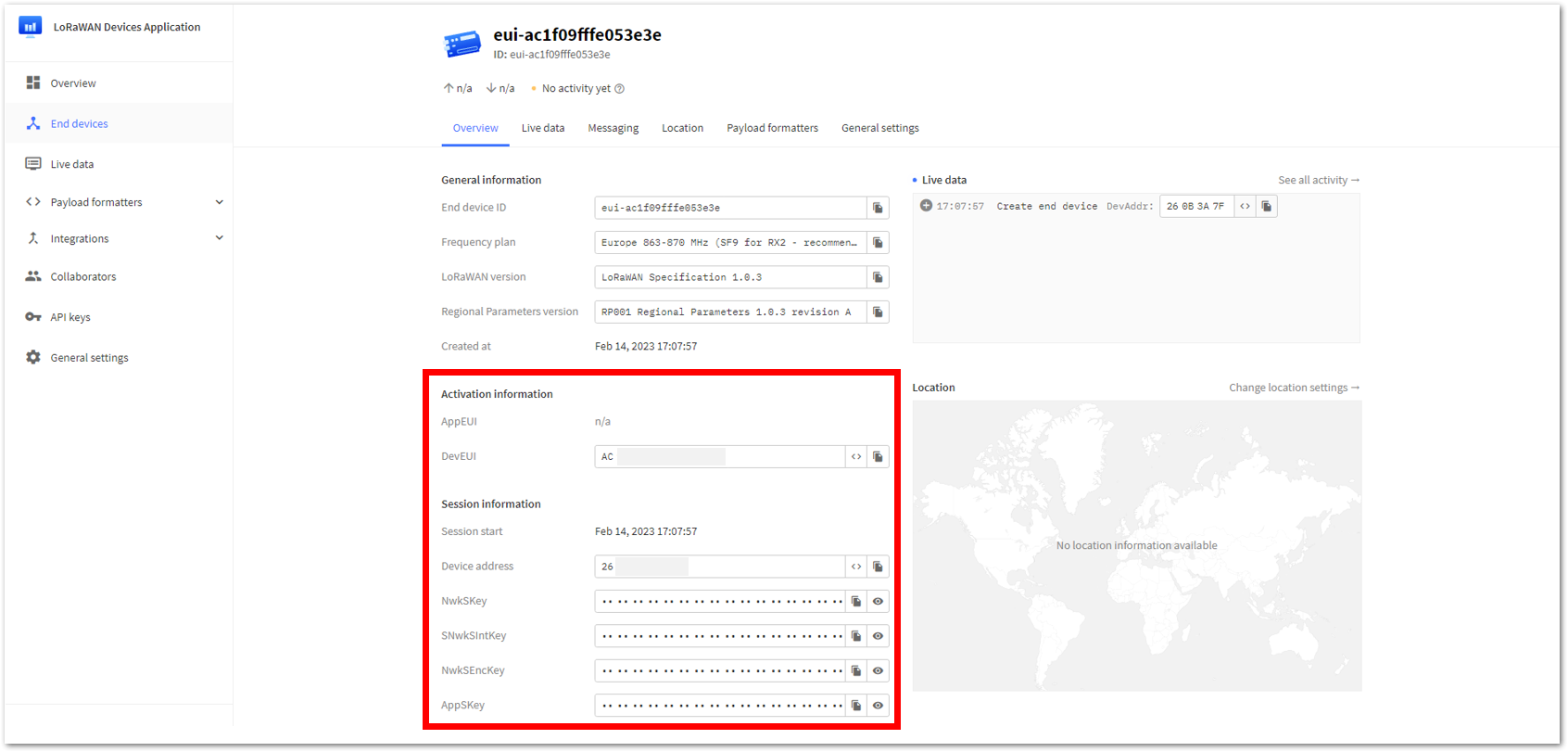 Figure 1: Your created ABP device from your TTN console
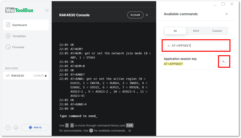 Figure 1: Setting up your Console
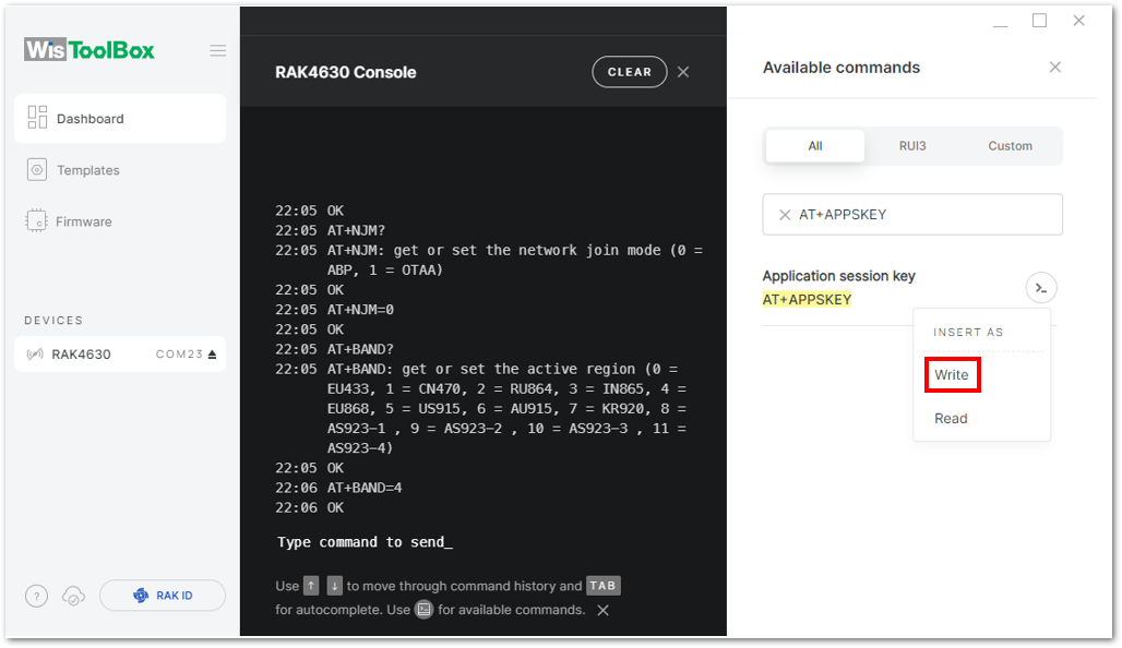 Figure 1: Setting up your Console
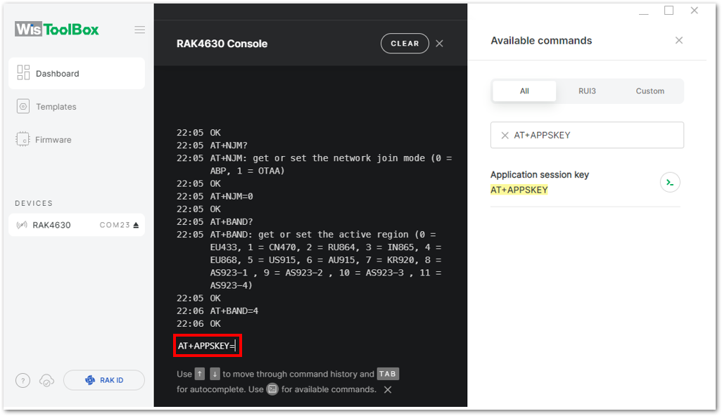 Figure 1: Setting up your Console
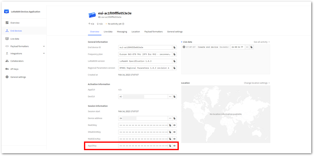 Figure 1: Copying the AppSKey credential from TTN to WisToolBox
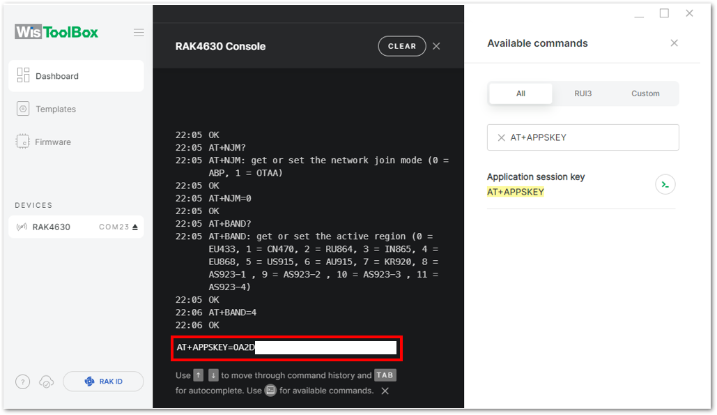 Figure 1: Setting up your Console
- Repeat the same procedure for the Device Address and Network Session Key (NwkSKey).
- For Device address
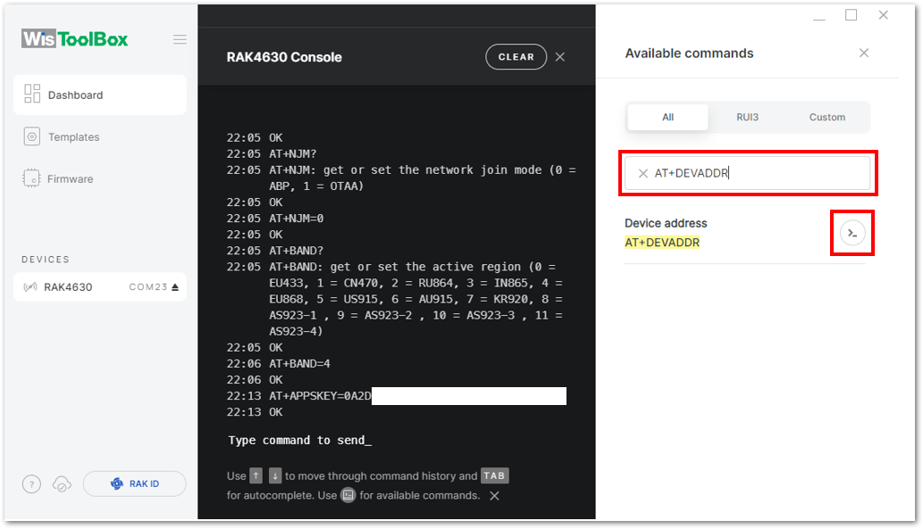 Figure 1: Setting up your Console
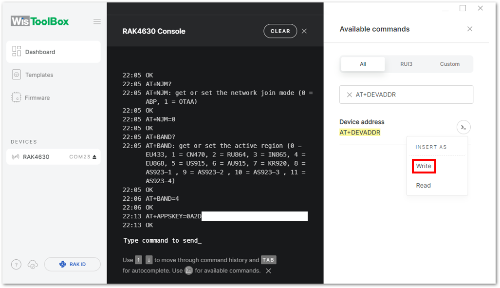 Figure 1: Setting up your Console
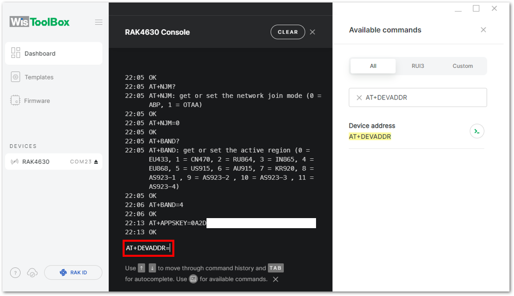 Figure 1: Setting up your Console
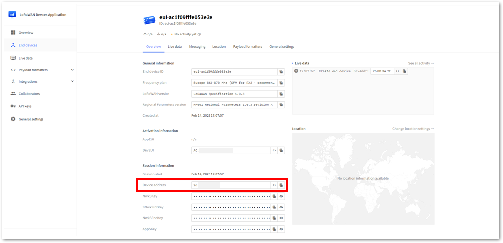 Figure 1: Copying the Device address credential from TTN to WisToolBox
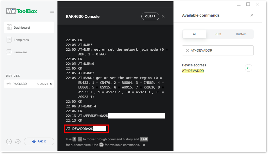 Figure 1: Setting up your Console
- For Network session key (NwkSKey)
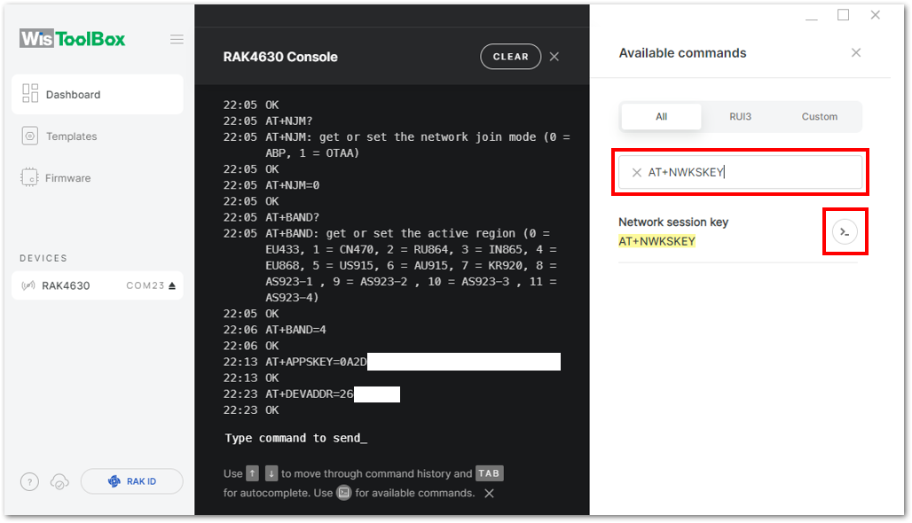 Figure 1: Setting up your Console
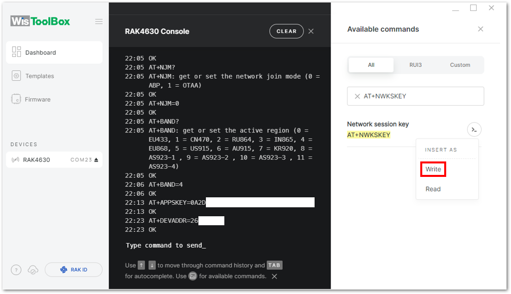 Figure 1: Setting up your Console
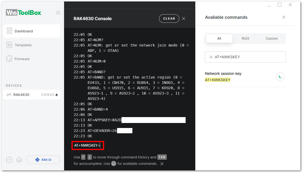 Figure 1: Setting up your Console
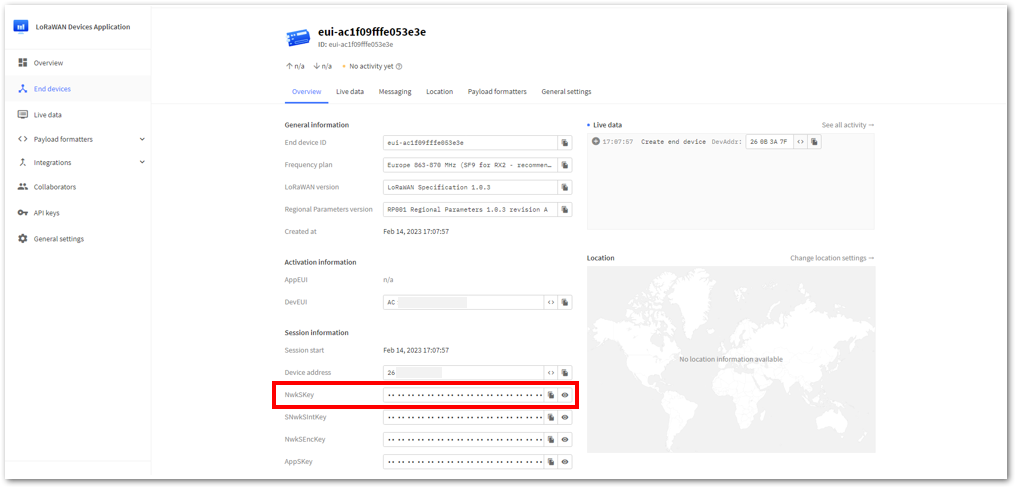 Figure 1: Copying the NwkSKey credential from TTN to WisToolBox
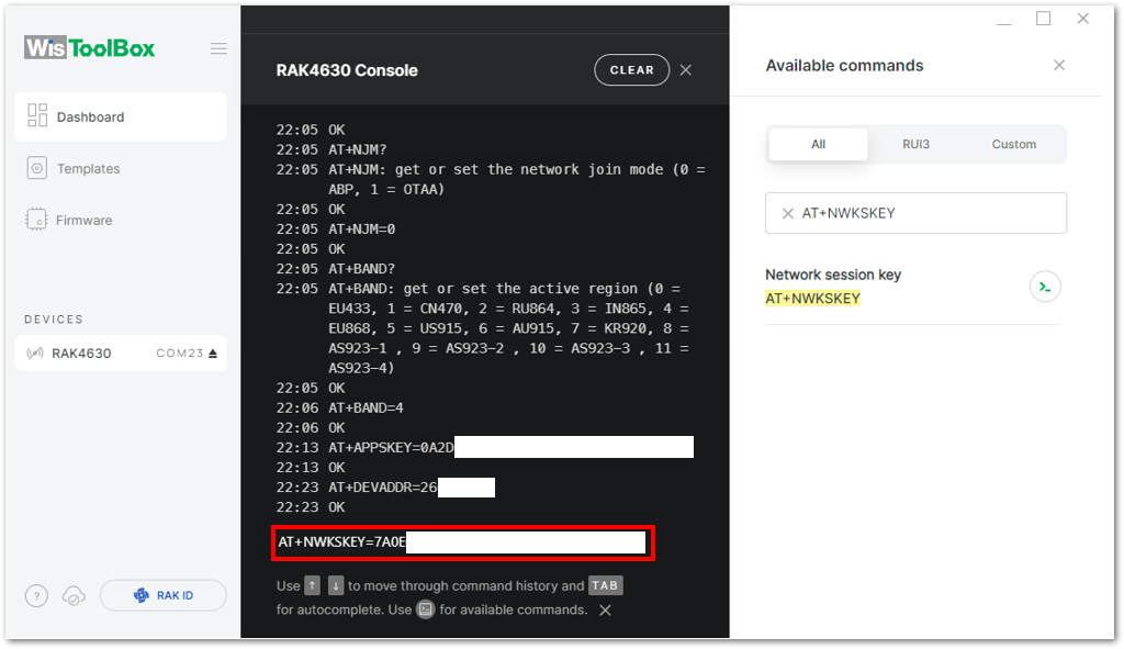 Figure 1: Setting up your Console
- Once completed, click Dashboard to verify the updated credentials of your ABP device. Then, click PARAMETERS to open the Global Settings and LoRaWAN keys, ID, EUI sections to confirm that they have been updated accordingly.
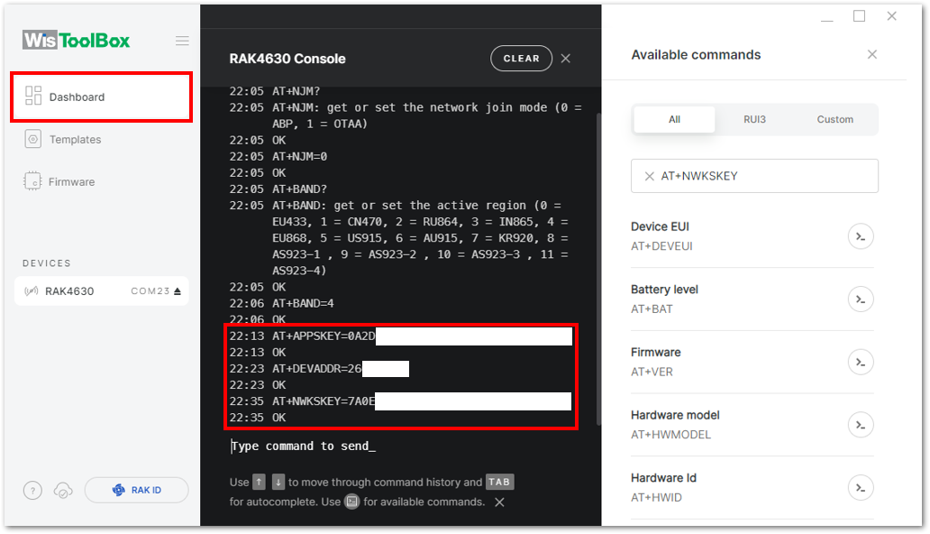 Figure 1: Setting up your Console
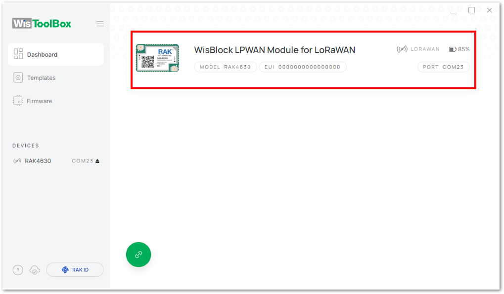 Figure 1: Setting up your Console
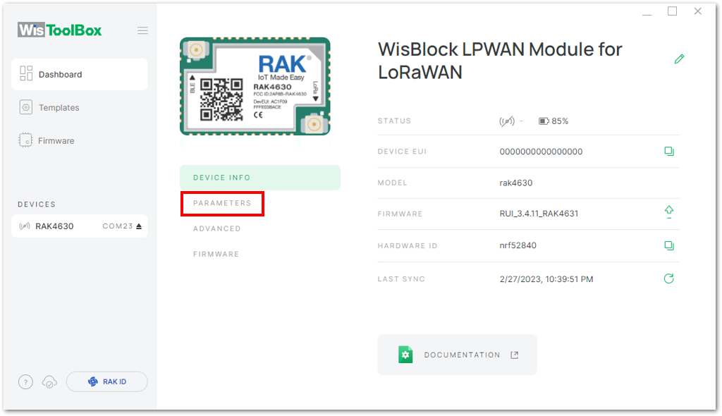 Figure 1: PARAMETERS
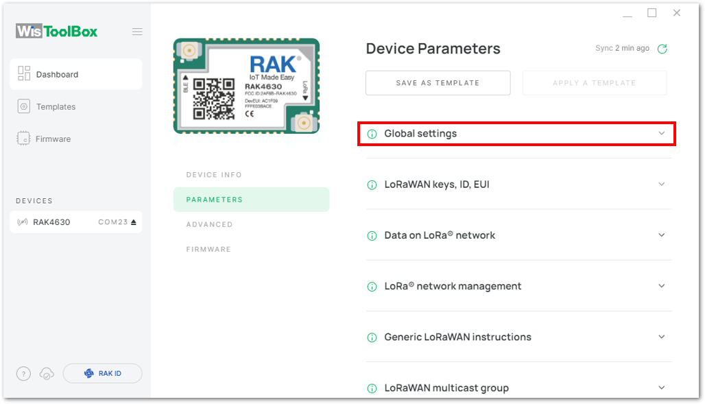 Figure 1: Global settings and LoRaWAN keys, ID, EUI
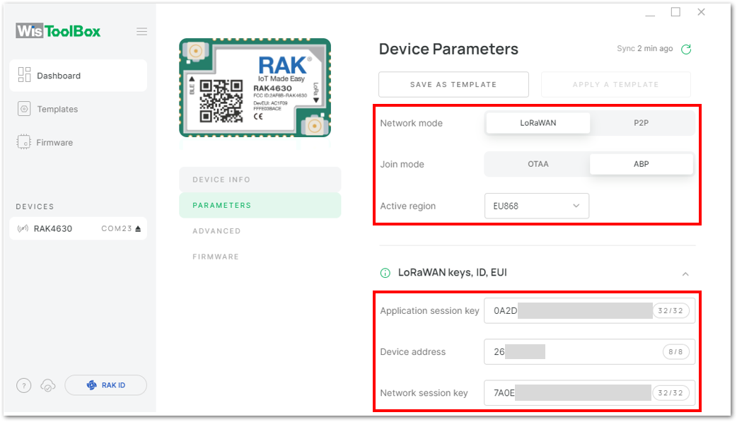 Figure 1: Global settings and LoRaWAN keys, ID, EUI details
Now you have a configured ABP device using WisToolBox Console. ABP-configured devices are directly tied to the network once done with the above procedures so joining procedure is not needed.
- Try sending the payload to TTN. Open again the terminal console of WisToolBox to send some payload. Send the command format:
AT+SEND=<port>:<payload>
AT+SEND=2:12345678
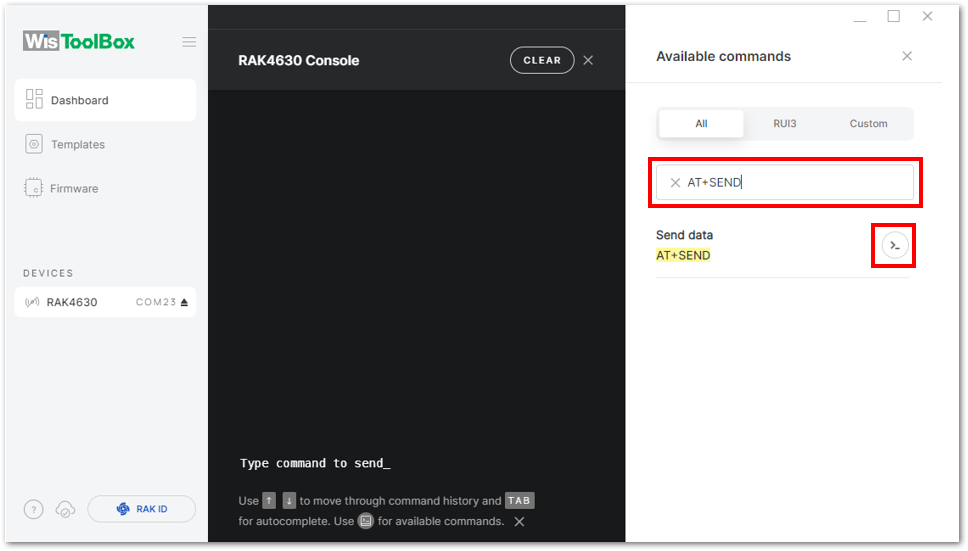 Figure 1: ABP device sending payload to the network
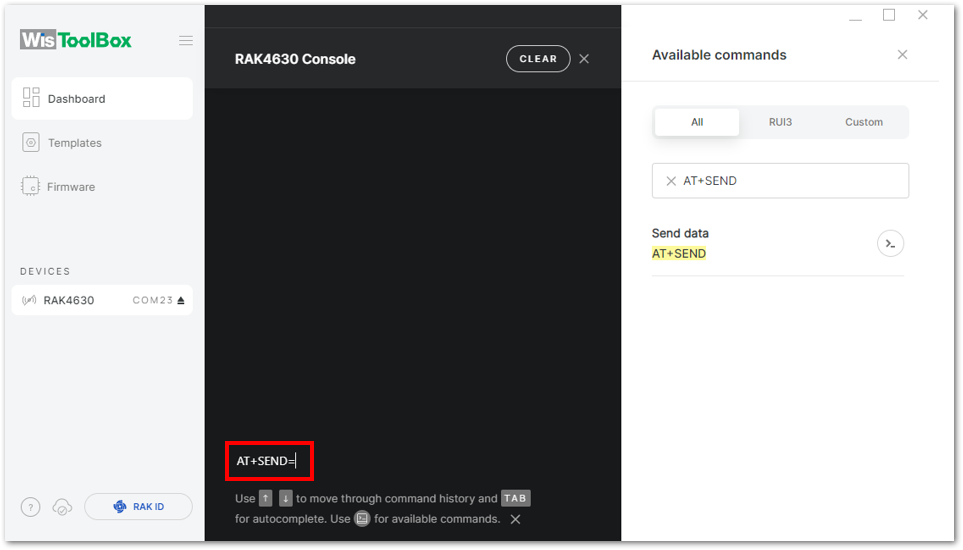 Figure 1: ABP device sending payload to the network
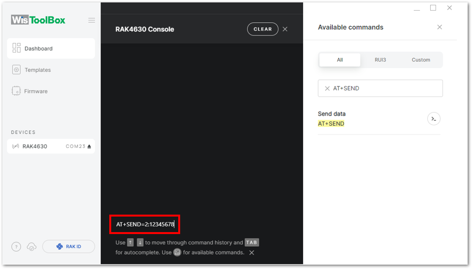 Figure 1: ABP device sending payload to the network
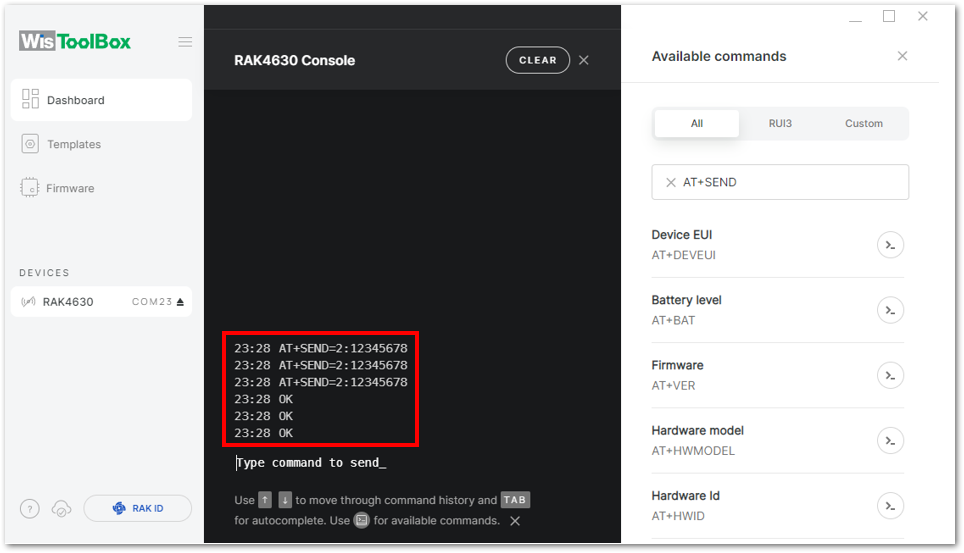 Figure 1: ABP device sending payload to the network
- You can see the data sent by the RAK4630 module on the TTN device console Live data section. Also, the Last seen info should be a few seconds or minutes ago.
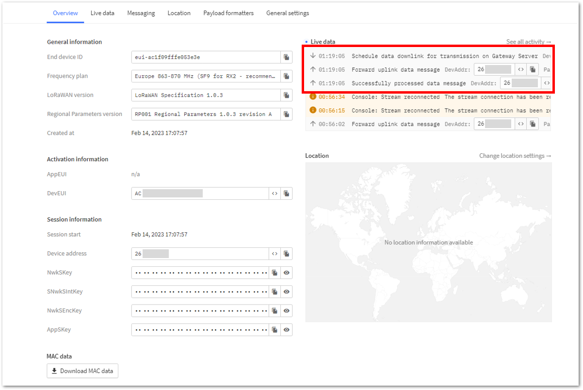 Figure 1: ABP Test Sample Data Sent Viewed in TTN
Connecting with ChirpStack
This section shows how to connect the RAK4630 module to the ChirpStack platform.
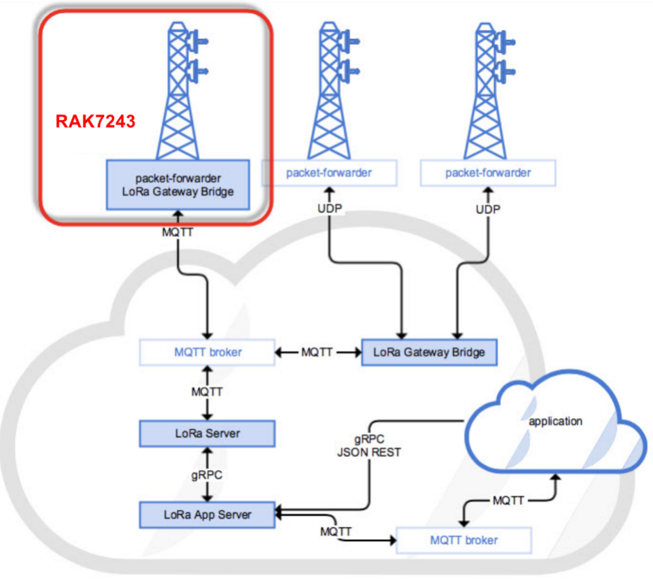 Figure 1: RAK4630 Module in the context of the ChirpStack platform
The ChirpStack, formerly known as the LoRaServer project, offers open-source components tailored for constructing LoRaWAN networks. Similar to TTN, the RAK4630 module is situated at the edge and communicates data to backend servers via a LoRaWAN gateway. Learn more about ChirpStack.
In this guide, it is assumed that you are using a RAK Gateway and its built-in ChirpStack. Also, the gateway with the ChirpStack must be configured successfully. For further information, check the RAK documents for more details.
-
In summary, these are the requirements:
- In a ChirpStack online gateway, the frequency band of the nodes should be consistent with the frequency band of the gateway in use.
- RAK Serial Port Tool provided by RAK
- RAK4630 module
The frequency band utilized in the demonstration is EU868. Employ the high-frequency version of RAK4630, denoted as RAK4630 (H).
Create a New Application
- Log in to the ChirpStack server using your account and password.
- Go to the Application section, as shown in Figure 211.
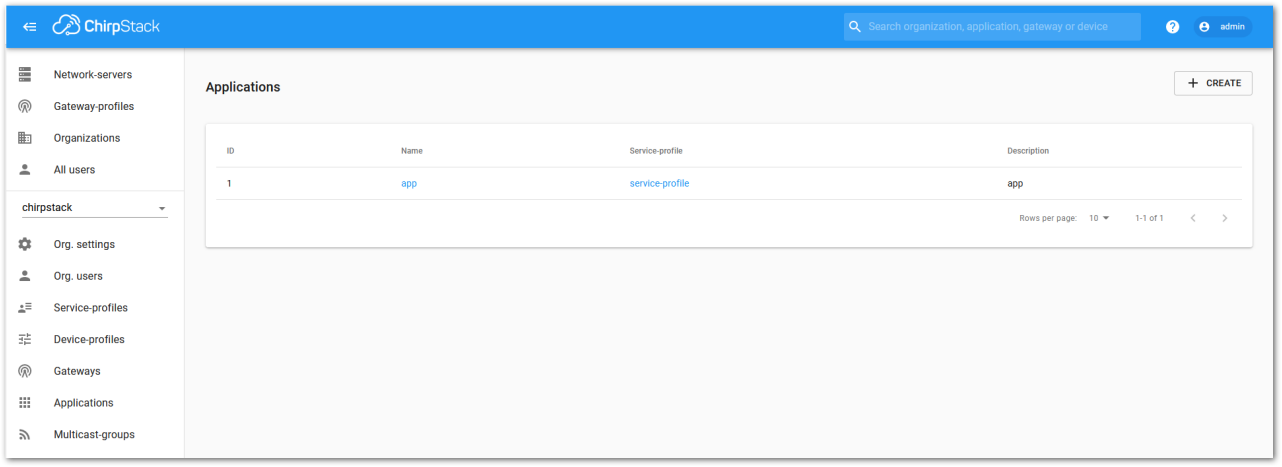 Figure 1: Application section
- By default, you should create a new application, although you can reuse existing ones. For this setup, create a new Application by clicking on the CREATE button and filling in the required parameters, as shown in Figure 212 and Figure 213.
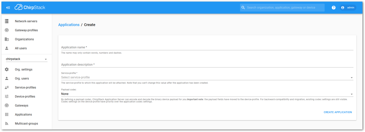 Figure 1: Creating a new application
For this setup, create an Application named rak_node_test.
ChirpStack LoRaServer supports multiple system configurations, although only one is enabled by default.
- Service profile: This field allows you to select the system profile.
- Payload codec: This field determines the parsing method for payload data, such as parsing LPP format data.
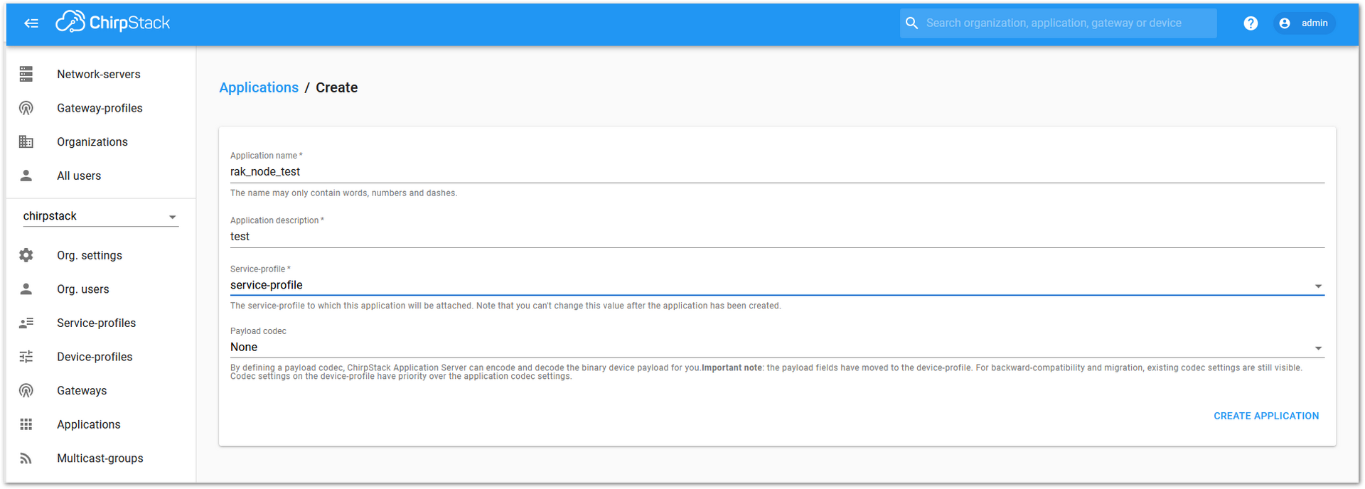 Figure 1: Filling in the parameters of an application
- Choose the Application created in the previous step, then select the DEVICES tab, as shown in Figure 214 and Figure 215.
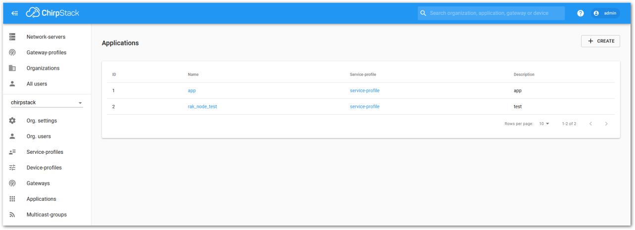 Figure 1: List of applications created
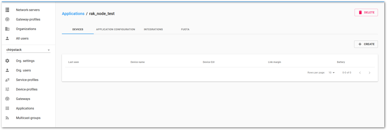 Figure 1: Device tab of an application
- Inside the DEVICE tab, create a new device (LoRaWAN node) by clicking on the + CREATE button.
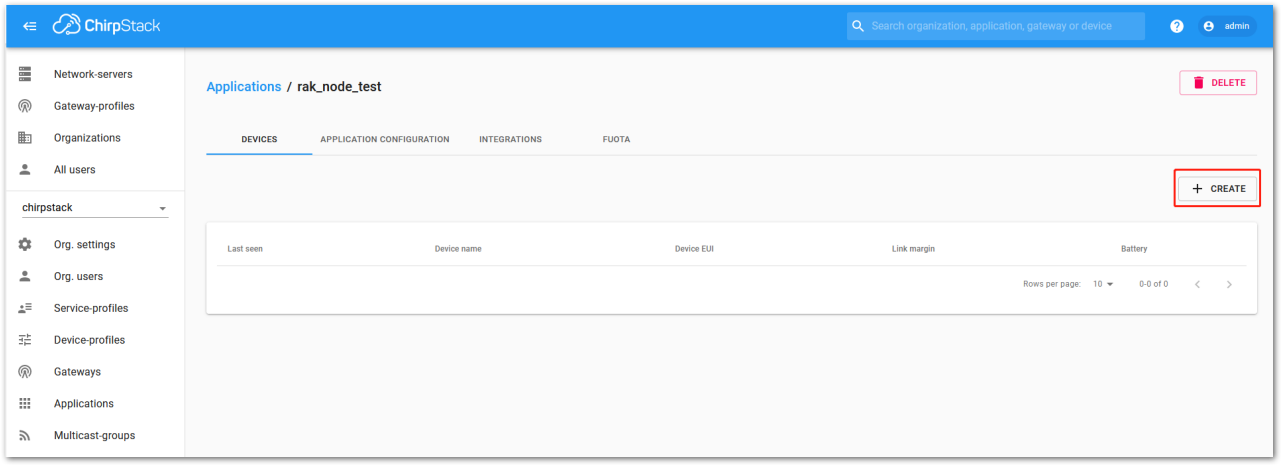 Figure 1: Add a new device
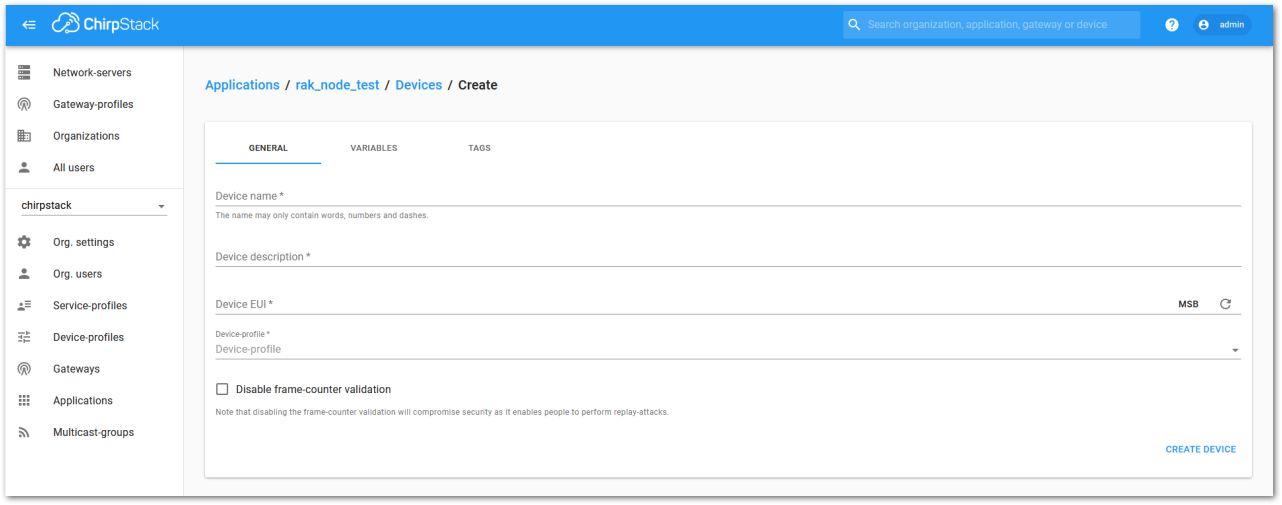 Figure 1: Chirpstack adding node into the RAK4630 Module
- Once the node is created, fill in the necessary data. You can generate a Device EUI automatically by clicking the load icon, or you can manually enter the correct Device EUI in the edit box.
Fill in the parameters requested:
- Device name and Device description: These are descriptive texts about your device.
- Device EUI: This interface allows you to generate a Device EUI automatically by clicking the generate icon. You can also add a specific Device EUI directly in the form.
- Device Profile:
- If you want to join in OTAA mode, select DeviceProfile_OTAA.
- If you want to join in ABP mode, select DeviceProfile_ABP.
Device profiles DeviceProfile_OTAA and DeviceProfile_ABP are only available if you are using the built-in ChirpStack LoRaWAN Server of RAK Gateways.
If you have your own Chirpstack installation, set up the device profile with LoRaWAN MAC version 1.0.4 and LoRaWAN Regional Parameters revision B to make it compatible with RAK4630.
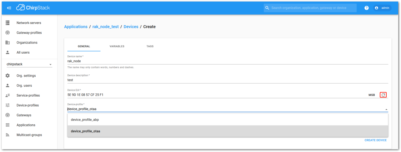 Figure 1: Generate a new Device EUI
 Chirpstack OTAA Device Registration
- If you have selected DeviceProfile_OTAA, as shown in Figure 219, after the device is created, an Application Key must also be created for this device.
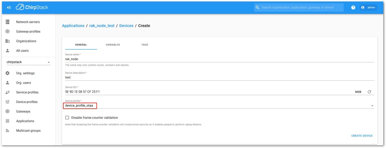 Figure 1: Chirpstack OTAA activation
- The previously created Application Key can be entered here, or a new one can be generated automatically by clicking the icon highlighted in red in Figure 220.
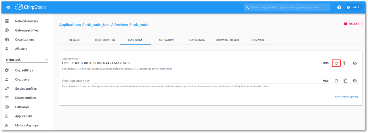 Figure 1: Chirpstack OTAA Set Application Keys
- Once the Application Key is added to the form, the process can be finalized by clicking on the SET DEVICE-KEYS button.
- As shown in Figure 221, a new device should be listed in the DEVICES tab. The most important parameters, such as the Device EUI, are shown in the summary.
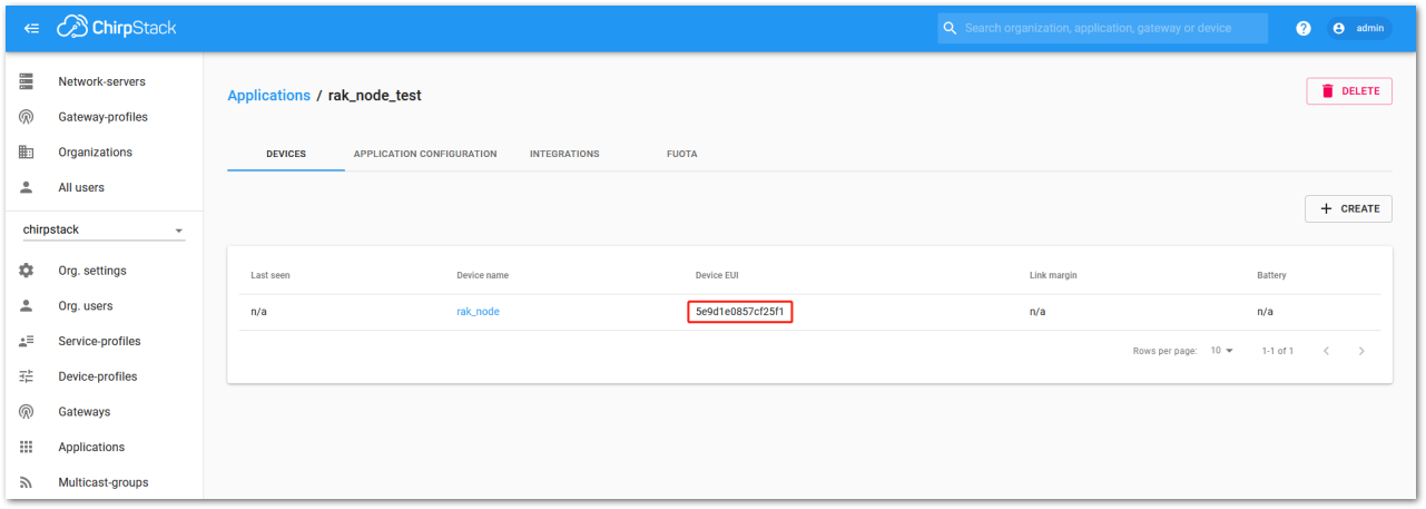 Figure 1: Chirpstack OTAA list of the device in the Device Tab
- To end the process, it is a good practice to review that the Application Key is properly associated with this device. The Application Key can be verified in the KEYS(OTAA) tab, as shown in Figure 222.
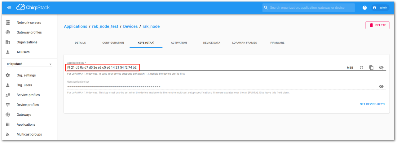 Figure 1: Application key associated with the new device
Standard OTAA mode requires the Device EUI, Application Key, and Application EUI, but in ChirpStack’s implementation, only the Device EUI and the Application Key are mandatory. The Application EUI is not required and not recorded in the Application tab. Nevertheless, you can reuse the Device EUI as the Application EUI during the configuration on the side of the node.
OTAA Configuration for Chirpstack
The RAK4630 module supports a series of AT commands to configure its internal parameters and control the functionalities of the module.
- To set up the RAK4630 module to join the Chirpstack using OTAA, start by connecting the RAK4630 module to the Computer (see Figure 37) and open the RAK Serial Port Tool. Select the right COM port and set the baud rate to 115200.
It is recommended to start by testing the serial communication and verify that the current configuration is working by sending these two AT commands:
AT
ATE
ATE will echo the commands you input to the module, which is useful for tracking the commands and troubleshooting.
You will receive OK when you input the two commands. After setting ATE, see all the commands you input together with the replies. Try again AT and you should see it on the terminal followed by OK, as shown in Figure 224.
If you haven't received an OK or any reply, you need to check if the wiring of your UART lines is correct and if the baud is correctly configured to 115200. Also, you can check if the device is powered correctly. If you are getting power from a USB port, ensure that you have a good USB cable.
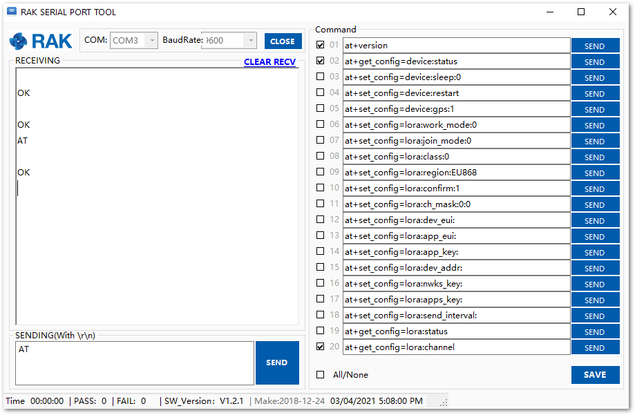 Figure 1: at+version command response
- The next step is to configure the OTAA LoRaWAN parameters in RAK4630:
- LoRa work mode: LoRaWAN
- LoRaWAN join mode: OTAA
- LoRaWAN class: Class A
- LoRaWAN region: EU868
Set the work mode to LoRaWAN. You might need to reconnect on the Serial Terminal Software Tool if you lost connection after using the AT+NWM=1 command.
AT+NWM=1
Set the LoRaWAN activation to OTAA.
AT+NJM=1
Set the LoRaWAN class to Class A.
AT+CLASS=A
Set the frequency/region to EU868.
AT+BAND=4
Depending on the Regional Band you selected, you might need to configure the sub-band of your RAK4630 to match the gateway and LoRaWAN network server. This is especially important for Regional Bands like US915, AU915, and CN470.
To configure the masking of channels for the sub-bands, you can use the AT+MASK command that can be found on the AT Command Manual.
To illustrate, you can use sub-band 2 by sending the command AT+MASK=0002.
List of band parameter options
| Code | Regional Band |
|---|---|
| 0 | EU433 |
| 1 | CN470 |
| 2 | RU864 |
| 3 | IN865 |
| 4 | EU868 |
| 5 | US915 |
| 6 | AU915 |
| 7 | KR920 |
| 8 | AS923 |
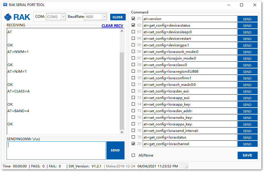 Figure 1: Configuring LoRa parameters
- After the configuration of the LoRaWAN parameters, the next step is to set up the DevEUI and AppKey. You need the use the values from the Chirpstack device console.
The Application EUI parameter is not required in the ChirpStack platform; therefore, it is possible to use the same id as the Device EUI.
- Device EUI: 5E9D1E0857CF25F1
- Application EUI: 5E9D1E0857CF25F1
- Application Key: F921D50CD7D02EE3C5E6142154F274B2
Set the Device EUI.
AT+DEVEUI=5E9D1E0857CF25F1
Set the Application EUI.
AT+APPEUI=5E9D1E0857CF25F1
Set the Application Key.
AT+APPKEY=F921D50CD7D02EE3C5E6142154F274B2
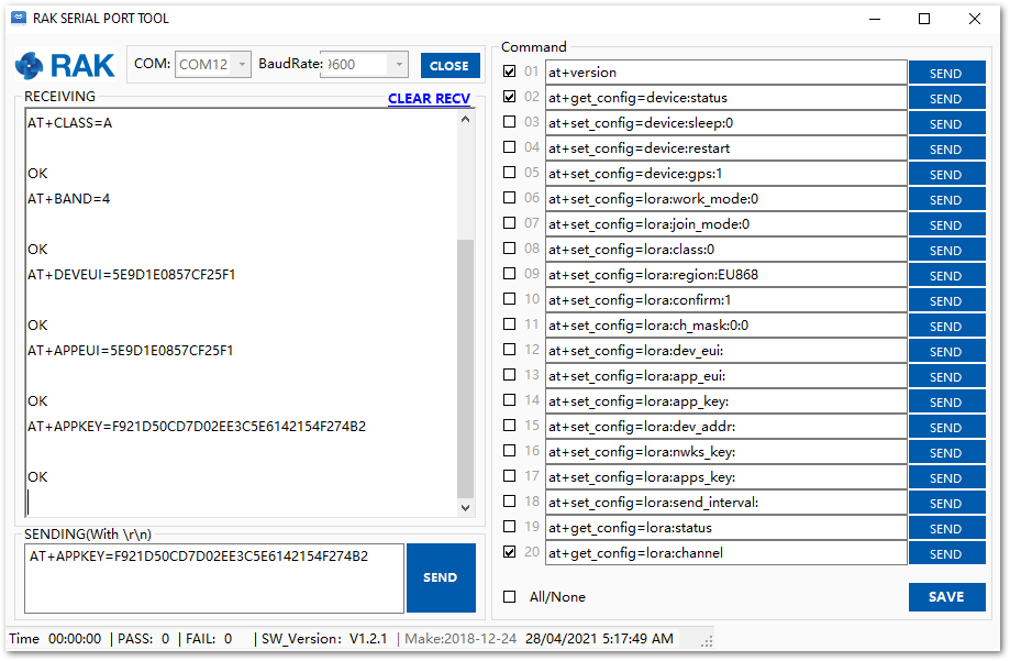 Figure 1: Configuring LoRa Parameters
- After the EUI and key configuration, the device can now join the network and send some payload.
AT+JOIN=1:0:10:8
Join command format: AT+JOIN=w:x:y:z
| Parameter | Description |
|---|---|
| w | Join command - 1: joining, 0: stop joining. |
| x | Auto-join config - 1: auto-join on power-up, 0: no auto-join |
| y | Reattempt interval in seconds (7-255) - 8 is the default. |
| z | Number of join attempts (0-255) - 0 is default. |
After 5 or 6 seconds, if the request is successfully received by a LoRa gateway, you should see the JOINED status reply.
If the OTAA device failed to join, check if your device is within reach of a working LoRaWAN gateway that is configured to connect to Chirpstack. It is also important to check that all your OTAA parameters (DEVEUI and APPKEY) are correct, using the AT+DEVEUI=? and AT+APPKEY=? commands. Lastly, ensure that the antenna of your device is properly connected.
After checking all the things above, try to join again.
- With the end-device properly activated, try to send some payload after a successful join.
AT+SEND=2:12345678
Send command format: AT+SEND=<port>:<payload>
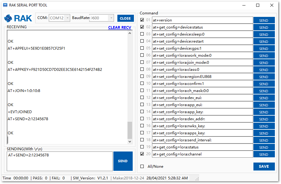 Figure 1: OTAA test sample data sent via RAK Serial Port Tool
On the ChirpStack platform, you should see the join and uplink messages in the LORAWAN FRAMES tab, as shown in Figure 227. By convention, messages sent from nodes to gateways are considered as Uplinks while messages sent by gateways to nodes are considered as Downlinks.
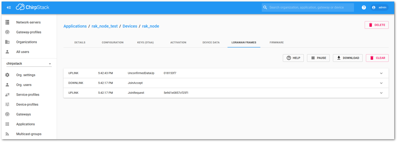 Figure 1: Chirpstack data received preview
Chirpstack ABP Device Registration
- During the registration of a new device, if you select DeviceProfile_ABP, as shown in Figure 228, the ChirpStack platform will assume that this device will join the LoRaWAN network using the ABP mode.
Check Disable counting frame verification. During testing, if the module is restarted, the frame counting number will also be reset to zero. This can lead to synchronization issues with the ChirpStack server, which may interpret it as a replay attack. While it's safe to disable this feature for testing purposes, remember to activate it in a production environment.
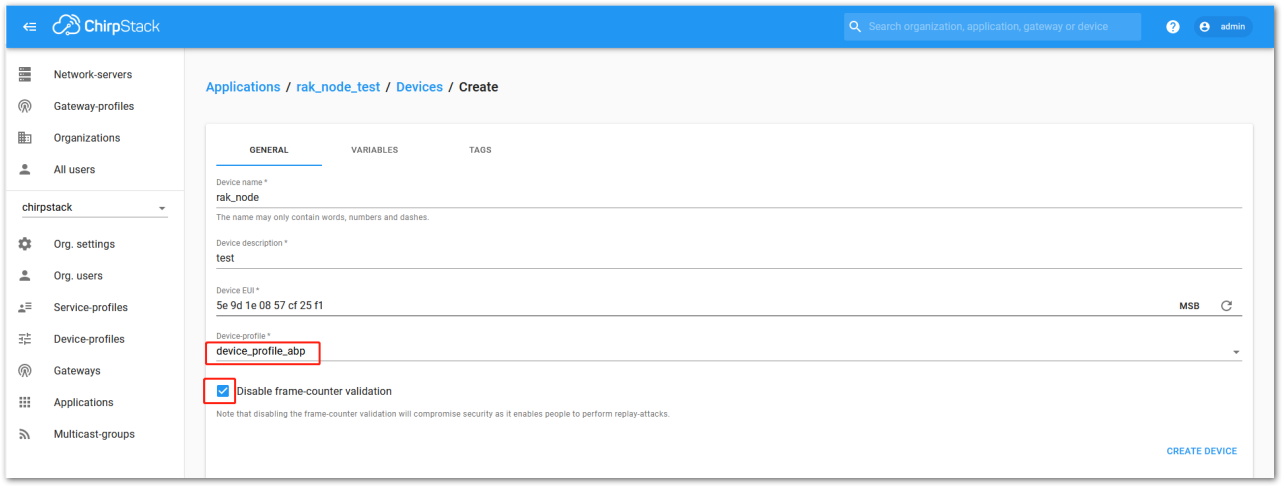 Figure 1: ChirpStack console, configuring a device
- After selecting the ABP mode, the following parameters appear in the Activation tab:
- Device Address
- Network Session Key
- Application Session Key
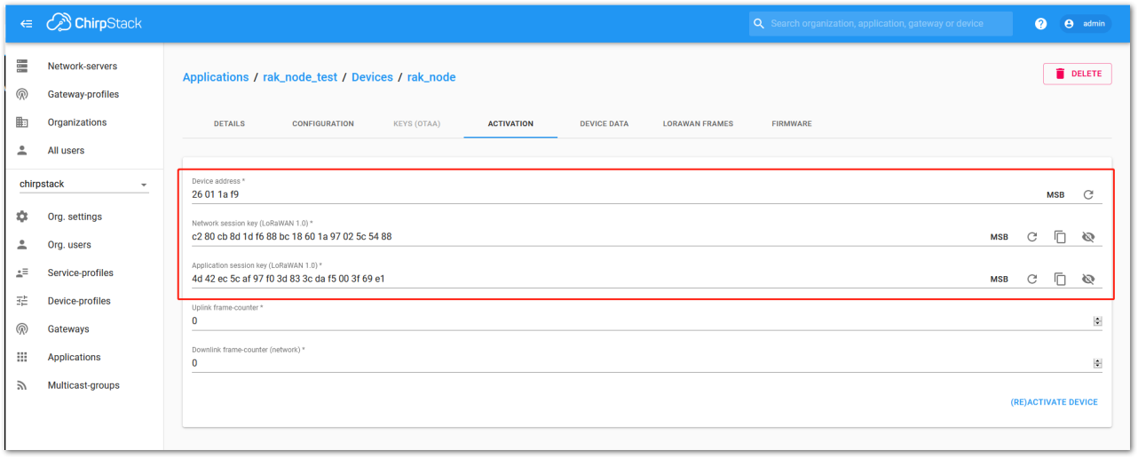 Figure 1: Chirpstack ABP activation parameters needed
- The parameters can either be generated as random numbers by the platform or set with user-defined values. Once these parameters are filled in correctly, the process is completed by clicking on the ACTIVATE DEVICE button.
ABP Configuration for Chirpstack
- To set up the RAK4630 module to join the Chirpstack using ABP, start by connecting the RAK4630 module to the Computer (see Figure 41) and open the RAK Serial Port Tool. Select the right COM port and set the baud rate to 115200.
It is recommended to start by testing the serial communication and verify that the current configuration is working by sending these two AT commands:
AT
ATE
ATE will echo the commands you input to the module, which is useful for tracking the commands and troubleshooting.
You will receive OK when you input the two commands. After setting ATE, you can see all the commands you input together with the replies. Try again AT and you should see it on the terminal followed by OK, as shown in Figure 230.
If haven't received an OK or any reply, you need to check if the wiring of your UART lines is correct and if the baud is correctly configured to 115200. Also, you can check if the device is powered correctly. If you are getting power from a USB port, ensure that you have a good USB cable.
 Figure 1: at+version command response
- The next step is to configure the ABP LoRaWAN parameters in RAK4630:
- LoRa work mode: LoRaWAN
- LoRaWAN join mode: ABP
- LoRaWAN class: Class A
- LoRaWAN region: EU868
Set the work mode to LoRaWAN. You might need to reconnect on the Serial Terminal Software Tool if you lost connection after using the AT+NWM=1 command.
AT+NWM=1
Set the LoRaWAN activation to ABP.
AT+NJM=0
Set the LoRaWAN class to Class A.
AT+CLASS=A
Set the frequency/region to EU868.
AT+BAND=4
Depending on the Regional Band you selected, you might need to configure the sub-band of your RAK4630 to match the gateway and LoRaWAN network server. This is especially important on Regional Bands like US915, AU915, and CN470.
To configure the masking of channels for the sub-bands, you can use the AT+MASK command that can be found on the AT Commands Manual.
To illustrate, you can use sub-band 2 by sending the command AT+MASK=0002.
List of band parameter options
| Code | Regional Band |
|---|---|
| 0 | EU433 |
| 1 | CN470 |
| 2 | RU864 |
| 3 | IN865 |
| 4 | EU868 |
| 5 | US915 |
| 6 | AU915 |
| 7 | KR920 |
| 8 | AS923 |
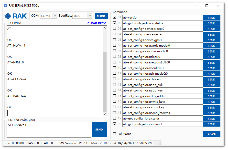 Figure 1: Configuring LoRa parameters
- After the configuration of the LoRaWAN parameters, the next step is to set up the device address and session keys. Use the values from the Chirpstack device console.
- Device Address: 26011AF9
- Application Session Key: 4D42EC5CAF97F03D833CDAf5003F69E1
- Network Session Key: C280CB8D1DF688BC18601A97025C5488
Set the Device Address.
AT+DEVADDR=26011AF9
Set the Application Session Key.
AT+APPSKEY=4D42EC5CAF97F03D833CDAf5003F69E1
Set the Network Session Key.
AT+NWKSKEY=C280CB8D1DF688BC18601A97025C5488
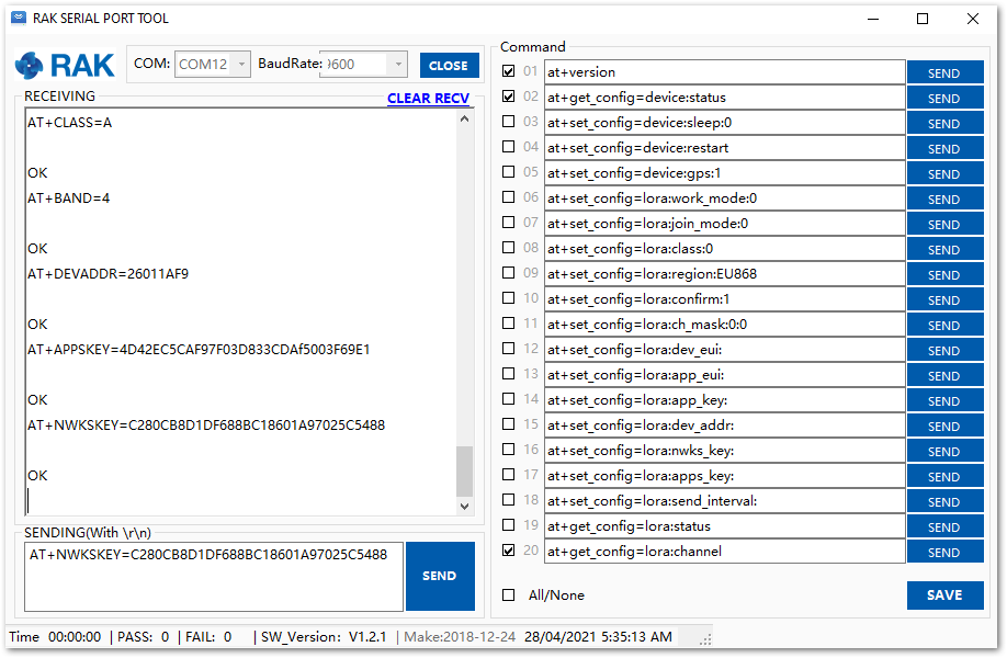 Figure 1: Configuring LoRa parameters
After the EUI and keys configuration, the device can now join the network and send some payload.
AT+JOIN=1:0:10:8
Join command format: AT+JOIN=w:x:y:z
| Parameter | Description |
|---|---|
| w | Join command - 1: joining, 0: stop joining. |
| x | Auto-join config - 1: auto-join on power-up, 0: no auto-join |
| y | Reattempt interval in seconds (7-255) - 8 is the default. |
| z | Number of join attempts (0-255) - 0 is default. |
-
After 5 or 6 seconds, if the request is successfully received by a LoRa gateway, you should see the JOINED status reply.
-
You can now try to send some payload after a successful join.
AT+SEND=2:12341234
Send command format: AT+SEND=<port>:<payload>
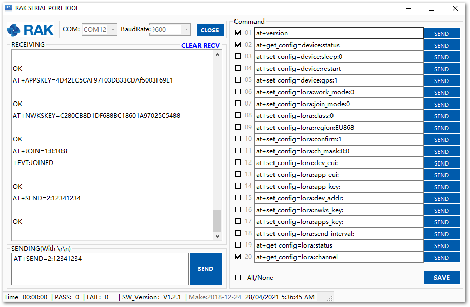 Figure 1: ABP test sample data sent via RAK Serial Port Tool
LoRa P2P Mode
This section demonstrates how to set up and connect two RAK4630 units to operate in LoRa P2P mode. The configuration of the RAK4630 units involves connecting them to a general-purpose computer using a USB-UART converter.
While the setup of each RAK4630 can be performed separately, testing the LoRa P2P mode requires both units to be connected simultaneously. This can be achieved by either using a single computer with two USB ports or by employing two computers, each with one USB port.
It is recommended to start by testing the serial communication and verify the current configuration is working by sending these two AT commands:
AT
ATE
ATE will echo the commands you input to the module, which is useful for tracking the commands and troubleshooting.
You will receive OK when you input the two commands. After setting ATE, you can see all the commands you input together with the replies.
Try again AT and you should see it on the terminal followed by OK.
 Figure 1: AT command response
- To set up the RAK4630 to work in LoRa P2P mode, enter the work mode command on both RAK4630 modules. You might need to disconnect and reconnect the module as it changes its mode of operation if you are sending commands via USB.
AT+NWM=0
- For this P2P setup, the LoRa parameters are the following:
- Link frequency: 868000000 Hz
- Spreading factor: 7
- Bandwidth: 125 kHz
- Coding Rate: 0 = 4/5
- Preamble Length: 10
- Power: 14 dBm
AT+P2P=868000000:7:125:0:10:14
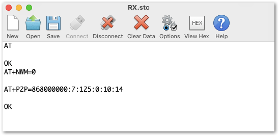 Figure 1: P2P Setup
Refer to the P2P Mode section of the AT command documentation to learn more about the definition of the parameters used.
- To set one module as a receiver (RX), set the value of the P2P to receive a command to 65535.
AT+PRECV=65535
With one module configured as RX, the other device will be the TX. You can now try to send a P2P payload.
AT+PSEND=11223344
- If the
AT+PRECVvalue is set to 65534, the device will continuously listen to P2P LoRa TX packets without any timeout. This is the same as setting the device in RX mode. - If the
AT+PRECVvalue is set to 65535, the device will listen to P2P TX without a timeout. But it will stop listening once a P2P LoRa packet is received to save power. - If the
AT+PRECVvalue is 0, the device will stop listening to P2P TX data. The device is in TX mode.
 Figure 1: P2P Sending and Receiving LoRa packets
AT Command Over BLE
This section shows how to use AT Commands over BLE using a Serial Bluetooth Terminal.
All available commands can be found in the AT Command Manual section of this document.
- Download and install the Serial Bluetooth Terminal to connect the device.
- Make sure the Bluetooth on your mobile is turned on.
- Select Category then Devices.
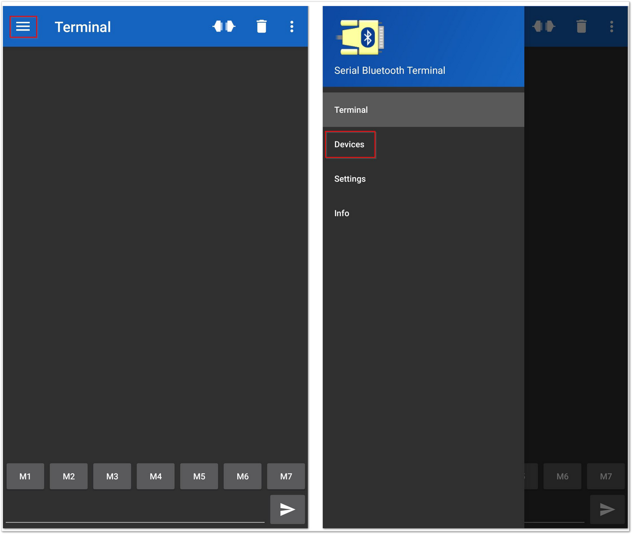 Figure 1: Available Serial Bluetooth Terminal
- Select the Bluetooth LE icon and click the SCAN icon to scan the device.
- Look for a BLE Device named RAK.XXXXXX in the scanner list of the app and connect to this device.
By default, the BLE signal of the RAK4630 has turned off automatically if no connection is established after 30 seconds. Connect to the BLE signal of the RAK4630 immediately after pressing the reset button.
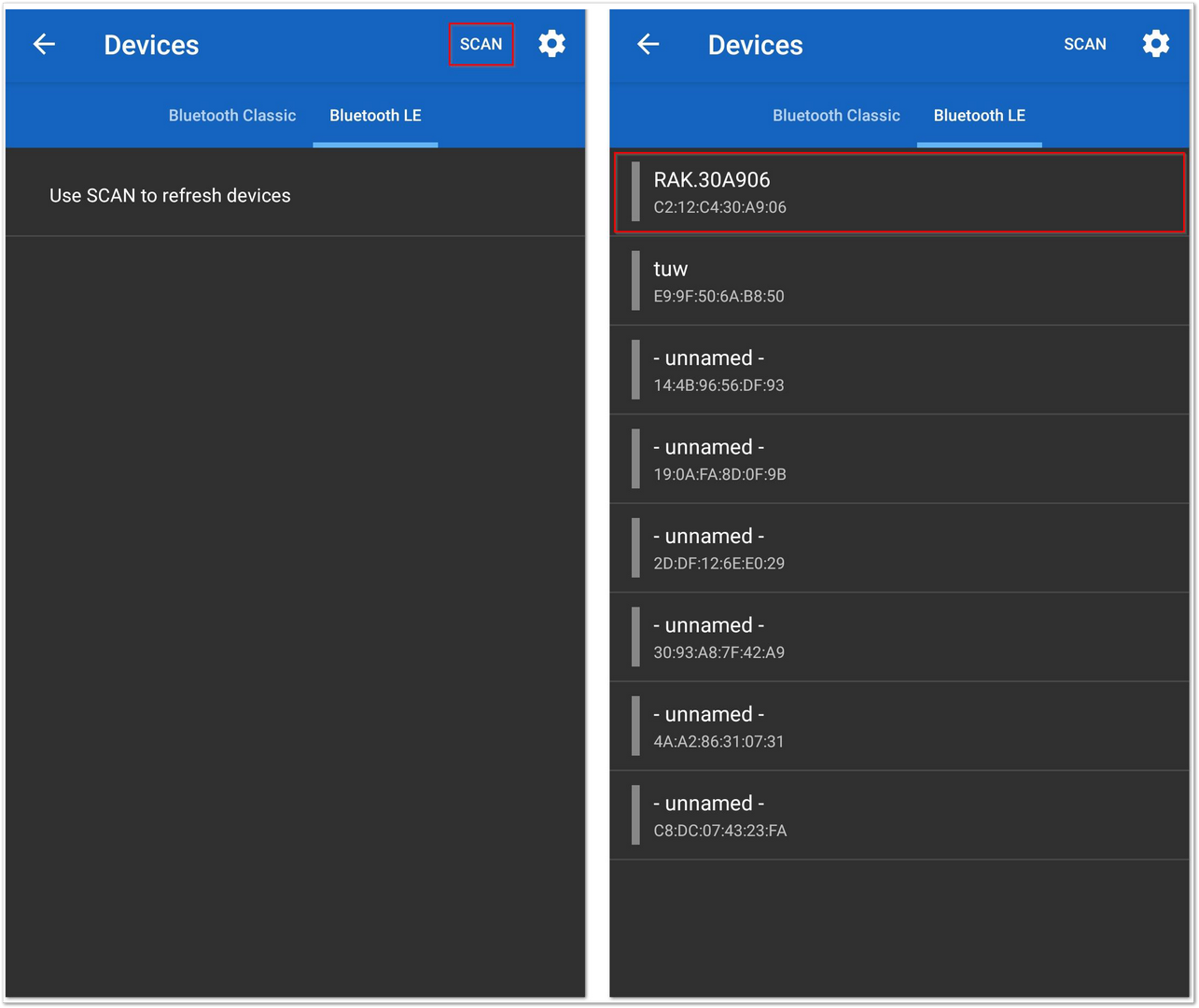 Figure 1: Scanning devices
- Make sure the connection is successful with RAK.XXXXXX.
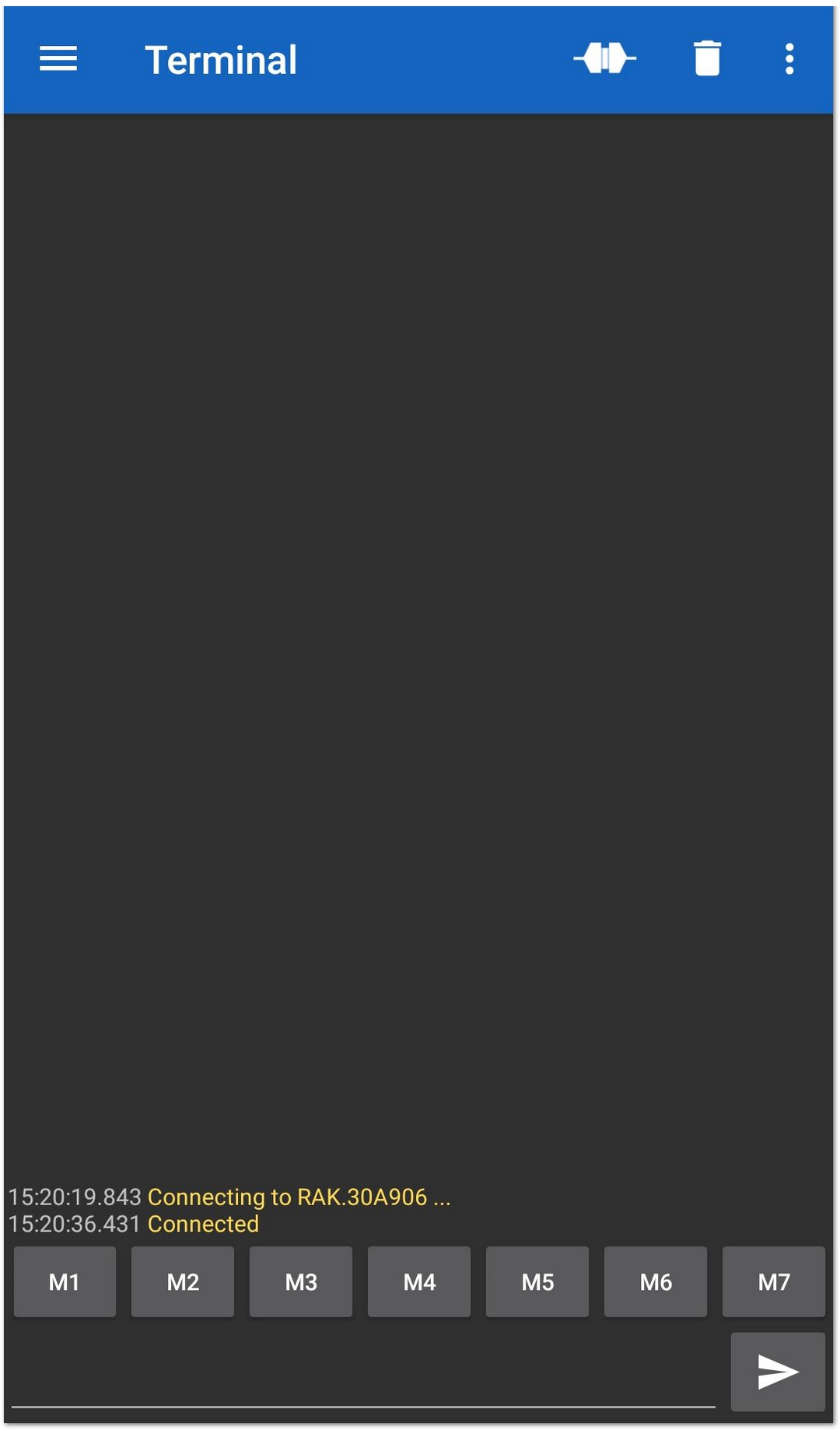 Figure 1: Connect with the device
- Send an AT Command and check remote console is received or not.
at+ver=?
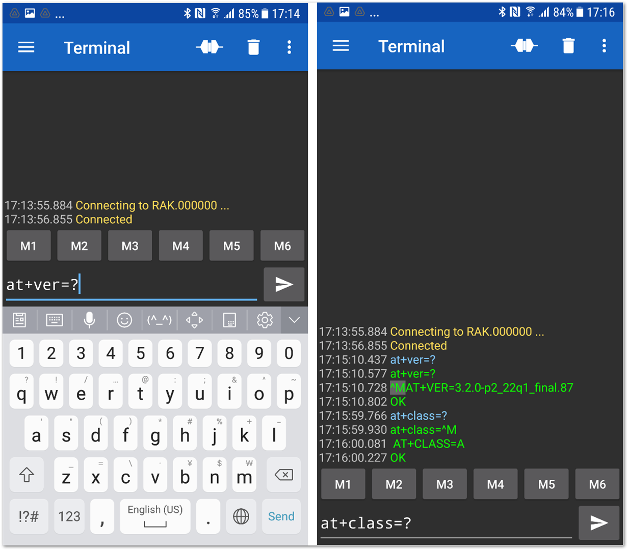 Figure 1: RAK4630 default Bluetooth ID after resetting
- The remote device will receive the same AT Commands.
at+ver=?
AT+VER=3.2.0-p2_22q1_final.87

OK

at+class=?
AT+CLASS=A

OK
Miscellaneous
Arduino Installation
Go to Arduino official website and download the Arduino IDE. You can see the multiple versions available for Windows, Linux, and Mac OS X. Choose the correct version of Arduino IDE and download it.
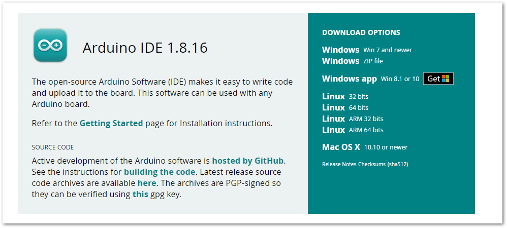 Figure 1: Arduino IDE latest version
Windows
For Windows 10 users: Do NOT install the Arduino IDE from the Microsoft App store. Install the original Arduino IDE from the Arduino official website instead, since the Arduino app from the Microsoft App Store has problems using third-party Board Support Packages.
-
Install the Arduino IDE, which you just downloaded, on your Windows PC.
-
Click I Agree then Next to proceed.
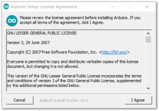 Figure 1: Arduino setup license agreement
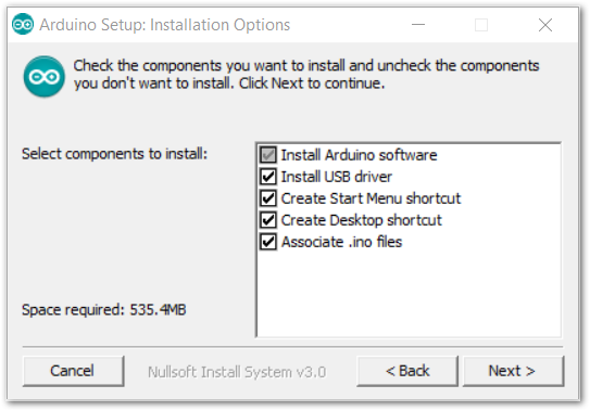 Figure 1: Arduino setup installation options
- Click Install.
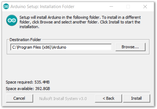 Figure 1: Installing Arduino IDE
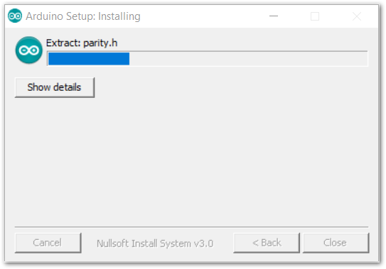 Figure 1: Ongoing installation
After 100% progress, the Arduino IDE has been installed successfully.
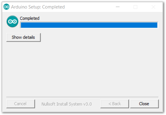 Figure 1: Successful installation
Linux
First, you need the check the compatibility with your system and choose between the 32-bit, 64-bit, and ARM versions of the Arduino IDE for Linux.
Installing via a tarball
After downloading the correct Arduino version, open a terminal, then run ls to check the installation file on the download folder.
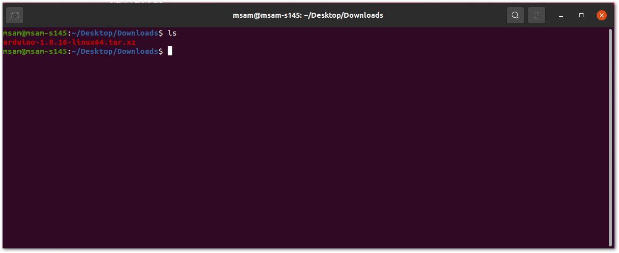 Figure 1: Check the download folder
A tarball is a type of compressed folder, like a .zip file, commonly used to distribute software in Linux. To extract the files from the tarball, change the directory to where the downloaded tarball is, then run:
tar xvf arduino-version.xz
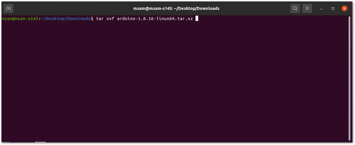 Figure 1: Tarball extract command
When the tar command finishes, run ls again. A folder named arduino-version will be created.
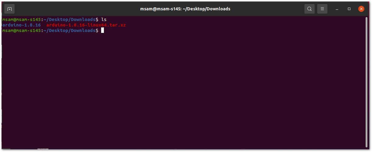 Figure 1: Arduino install folder created
Change the current directory and go to the newly created folder directory. There will be a file named install.sh in the folder. Execute sudo ./install.sh to install the Arduino IDE.
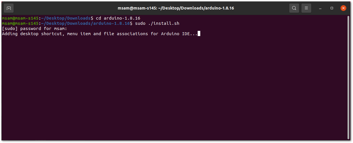 Figure 1: Arduino install script running
The sudo command temporarily elevates privileges allowing the installer to complete sensitive tasks without logging in as the root user.
Mac OS X
In Mac OS X, similar to Linux, there is no installation process. It is just a process of decompression, then you can open Arduino IDE successfully.
Arduino IDE Parts Guide
Figure 251 shows the five (5) parts of Arduino IDE.
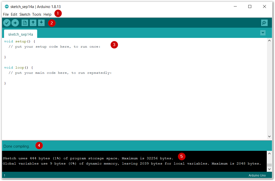 Figure 1: Arduino IDE
- IDE Option Menu
You can configure some general parameters such as the serial port, the board information, the libraries, the edit parameters, and so on.
- Operating Buttons
The operating buttons have five operations:
- Verify/Compile the source code.
- Upload the compiled code into WisBlock.
- Open a New Arduino IDE window or existing application.
- Save the current application.
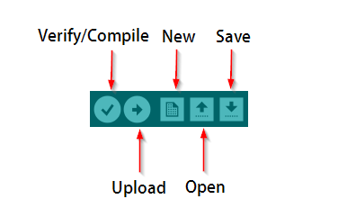 Figure 1: Operating buttons
- Code Area You can edit the source code, which will be compiled and uploaded into WisBlock later in this area.
- State Area
- Output Message Area You can see the output message in this area, whether it's a failure or success information.
