RAK10701-Plus Field Tester for LoRaWAN Network Setup
Before conducting any field tests, it’s essential to set up the Field Tester Plus, configure your LoRaWAN gateway, and ensure all system components are properly connected.
Prerequisites
Ensure that the following hardware and software components are ready:
Hardware Requirements
- RAK10701-Plus Field Tester (LoRaWAN end device)
- LoRa Sub-GHz Antenna (RP-SMA connector)
- USB Type-C Cable (for charging and optional advanced configuration)
- RAK Gateway running WisGateOS 2 with Field Test Data Processor Extension installed
If you purchased the Field Tester Plus Bundle, the included gateway comes pre-installed with the required Field Test Data Processor Extension.
Software Requirements
- Field Test Data Processor Extension for WisGateOS 2: To install the extension, see the guide:
- WisToolBox: Used for configuring OTAA parameters (DevEUI, AppEUI, and AppKey) and supporting firmware updates.
Field Tester Plus Configuration
Before configuring the Field Tester Plus, it’s important to understand the physical interfaces, display layout, and basic operations of the device. For detailed specifications, refer to the Field Tester Plus Datasheet.
Device Configuration
This section describes the basic parameter settings that can be configured directly on the device via the touchscreen.
- Connect the LoRa Sub-GHz antenna (RP-SMA connector) to the device.
- Press and hold the side button for 5 seconds to turn on the Field Tester Plus.
 Figure 1: Power On Screen
- Once powered on, the main screen will appear.
No data will be shown on first boot until a valid uplink occurs.
 Figure 1: Field Tester Main Screen
- Tap the gear icon on the screen to open the SETTINGS menu.
 Figure 1: Field Tester Settings
- Use the touch controls to adjust LoRa parameters (e.g., Band, DR, TX Power).
-
Tap the
 icon to cycle through available parameters (e.g., Band, DR, TX Power). The selected parameter will blink, indicating it is active.
 -
Tap the
 icon or
  icon to adjust and confirm the parameter’s value.
Editable Parameters:
Setting Description Values / Notes Location Labeling
Set a test point label (important for CSV export) Default: NULL
Max Length: 6 charactersBand
LoRaWAN regional frequency band RU864, IN865, EU868, US915, AU915, KR920, AS923-1/2/3/4 DR (Data Rate)
Affects signal range (lower DR = longer range) The available DR options vary by LoRaWAN regional frequency band. TX Power
Transmission power level The available TX Power options vary by LoRaWAN regional frequency band. TX Interval
Time between uplinks 6-3600 s Backlight
Screen brightness 0-10 ADR
Enable/disable Adaptive Data Rate ON/OFF
- After configuration, tap OK twice to save and exit.
 Figure 1: Field Tester Apply Changes
LoRaWAN OTAA Credentials Setup
The Field Tester Plus comes pre-configured with default DevEUI, AppEUI, and AppKey, so you can start testing immediately.
This setup step is optional and only required if you want to change the device credentials or register it to a different LoRaWAN® network.
The Field Tester Plus supports two configuration methods for setting DevEUI, AppEUI, and AppKey:
Mobile Configuration via WisToolBox App
Preparation
- Install WisToolBox from the App Store or Google Play.
- Power on your Field Tester Plus.
- Ensure Bluetooth is enabled on your phone and that it is placed near the device.
- Launch the WisToolBox App, then tap SATRT.
- Select BLE Pairing as the connection mode and tap CONNECT.
- Once the device appears on your phone (e.g.,
RAK10701.004474), tap the green link button to complete pairing. - After pairing, the app will display DEVICE INFO and PARAMETERS tabs. Go to the PARAMETERS tab and expand LoRaWAN® keys, ID, EUI.
- You can edit the following:
- Application EUI
- Application Key
- Device EUI
- After entering the credentials, tap APPLY.
- When completed, the device restarts and syncs automatically.
PC Configuration via USB (Desktop WisToolBox)
- Connect the Field Tester Plus to your PC using a USB Type-C cable.
- Launch WisToolBox for Desktop and click CONNECT to establish a connection with the Field Tester Plus.
 Figure 1: WisToolBox Connection Settings
If the connection fails, refer to the WisToolBox for Desktop | Installation and Setup Guide.
- Select the device and navigate to the ADVANCED tab.
 Figure 1: Field Tester Connected To WisToolBox
 Figure 1: Field Tester Advanced Commands
- Click OPEN CONSOLE, then enter the following AT commands:
| Command | Value Format |
|---|---|
AT+DEVEUI= | 8 bytes (64-bit hex, e.g. 70B3D57ED0012345) |
AT+APPEUI= | 8 bytes (64-bit hex) |
AT+APPKEY= | 16 bytes (128-bit hex) |
 Figure 1: WisToolBox AT Command Console
Field Test Data Processor Extension Installation
The Field Test Data Processor Extension is an optional application that runs on RAK WisGate Edge gateways powered by WisGateOS 2. It enables local signal analysis, CSV report generation, and heatmap visualization for data collected by the Field Tester Plus.
The extension communicates with LoRaWAN Network Servers via MQTT (subscribe/publish), and supports both Built-In and External LNS:
- RAK Gateways Built-in LNS
 Figure 1: Built-in LNS Setup
In this setup:
- Uplinks from the Field Tester are forwarded to the built-in LNS on the RAK Gateway.
- The extension subscribes to the MQTT Broker within the gateway to receive packets.
- This allows fully local processing, even without an external network. Best for offline, indoor, or portable testing setups.
- External LNS (e.g., ChirpStack, TTN, AWS IoT Core)
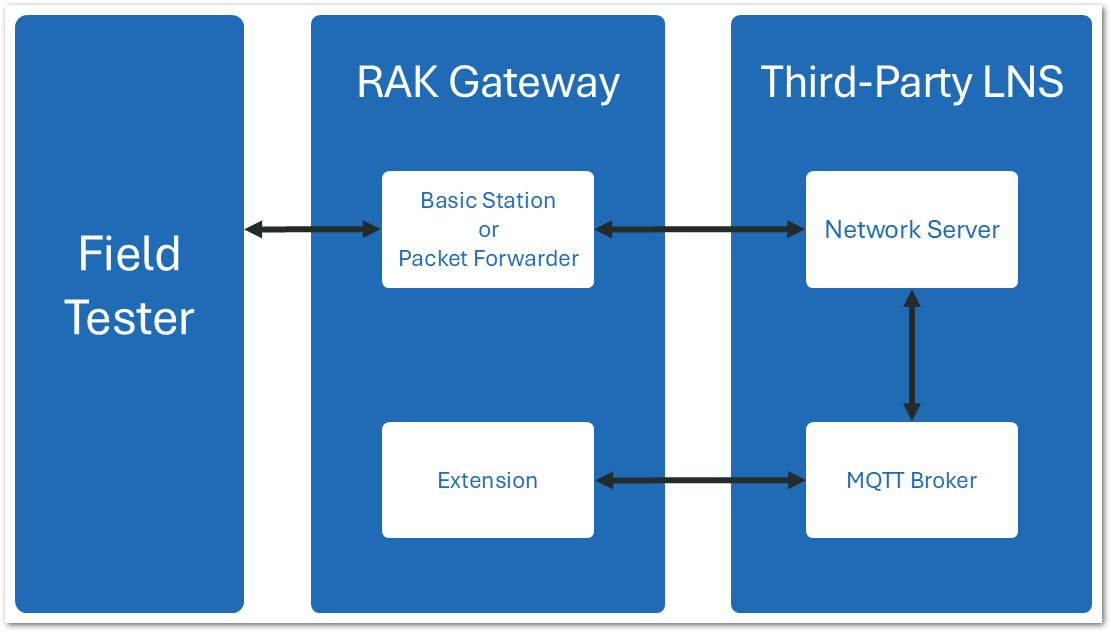 Figure 1: External LNS Setup
In this setup:
- The RAK Gateway uses Packet Forwarder or Basic Station mode to connect to an external LNS (e.g., ChirpStack, TTN, AWS IoT Core).
- The extension remains installed locally on the gateway and connects to the external MQTT broker of the LNS to receive packet metadata for analysis.
- Ideal for production deployments with cloud LNS platforms.
Installation Scenarios
- Field Tester Plus Bundle: The included gateway comes pre-installed with the Field Test Data Processor Extension.
- Other RAK WisGateOS 2 gateways: Manually install the extension via the WisGateOS 2 web interface. See: How to Add an Extension.
 Figure 1: WisGateOS 2 Extensions Menu
Set Up the Gateway and the Field Tester Plus for Your LNS
This section provides step-by-step instructions to:
- Connect your LoRaWAN gateway to your chosen LNS platform.
- Register the Field Tester Plus device to the network.
- Install and configure the Field Test Data Processor Extension to enable local data analysis and reporting.
Built-in LNS (WisGateOS 2)
Set Gateway to the Built-in Network Server
This section demonstrates how to connect your RAK gateway to a LoRaWAN Network Server (LNS).
- Log into the WisGateOS 2 web UI. Navigate to LoRa > Configuration.
- In the Work Mode section, select Built-in Network Server.
 Figure 1: LoRa Configuration Work Mode
- Select the log level and frequency band.
 Figure 1: Log And Frequency Band Configuration
Make sure the frequency band configured on the gateway matches the LoRaWAN Band setting of your Field Tester Plus.
Register the Field Tester Plus
- Ensure your gateway is configured to use the Built-in LNS. Navigate to LoRa > Applications tab.
- Click the Add application button (or the add one now link).
 Figure 1: Built LNS Application Menu
- You will be redirected to the application configuration page. Fill in the following fields:
 Figure 1: New Application Data Fields
- Application name: Name of the application.
- Application description: Description of the application (optional).
- Application Type
- Unified Application key: All devices will use the same application key.
- Separate Application keys: Each device or group of devices has a unique key.
- Auto Add Device: When enabled, devices with matching AppKey and Application EUI will be added automatically after a successful join request.
- Application Key: Required for Unified Application Key setup.
- Application EUI: Required for automatic device registration when Auto Add Device is enabled.
Refer to the Field Tester Plus Configuration section for matching AppKey and AppEUI setup.
- Click Save Application to complete the creation.
- Once the application is saved, navigate to: Your Application > Configuration. Click End Devices to proceed.
 Figure 1: Application End Devices Menu
- In the End device information interface, fill in the following information.
 Figure 1: End Device OTAA Configuration
- Activation Mode: Select OTAA. This value needs to be consistent with the value from the end device.
- End device (group) name: Name of the end device (group).
- End device description (optional) A description of the end device, optional.
- Class: Class A
- Frame Counter Width: Keep the default value.
-
Click Add end devices to enter the device adding page.
-
In the Adding end devices interface, enter the device EUI in the End Device EUI (main) field and click the Add to End Devices list button.
- Correct devices will appear under the End devices list.
- Duplicate devices will appear under End devices with error for correction.
 Figure 1: Add New End Device
- Click Add end devices to add the Field Tester Plus to the application.
Once registered, the Field Tester Plus will begin sending periodic uplinks to the Built-in LNS.
 Figure 1: End Device Field Tester Added
The device is currently operating in LinkCheck Mode, as the Field Test Data Processor Extension has not yet been configured. In this mode, the device screen will only display:
- Downlink RSSI/SNR
- Number of responding gateways
 Figure 1: Field Tester LinkCheck Mode
Next, install and configure the Field Test Data Processor Extension to enable full metric reporting (uplinks, packet loss, CSV export).
Configure Field Test Data Processor Extension for Built-in LNS
For detailed steps on configuring the Field Test Data Processor Extension for the Built-in LNS, the WisGateOS 2 Extension > Field Test > Built-in Network Server.
The Things Network (TTN)
Connect Gateway to TTN
This section explains how to connect and configure a RAK gateway with The Things Network (TTN), using the RAK7289V2 model as a reference.
Make sure the frequency band configured on the gateway matches the LoRaWAN Band setting of your Field Tester Plus.
To complete the TTN gateway setup, follow the instructions in RAK7289V2 LoRaWAN Network Server Guide | The Things Network (TTN).
Register Field Tester Plus on TTN
To connect your Field Tester Plus to The Things Network (TTN), a community-based LoRaWAN Network Server (LNS), visit the TTN Console at: https://console.cloud.thethings.network/
- Choose the appropriate cluster for your region. You can either select your country or manually choose the nearest TTN cluster.
 Figure 1: The Things Network Cluster Selection
- On the homepage, click Applications > + Add application
 Figure 1: The Things Network Add Application
- Add Application ID, Application name, and Description then click Create application.
 Figure 1: The Things Network Create Application
- Click Register end device within your newly created application.
 Figure 1: The Things Network Register End Device
- Choose Enter end device specifics manually. This will allow you to add the Frequency plan, LoRaWAN version, Regional Parameters version, and JoinEUI. The values of these parameters depend on the hardware you use. If your device has a preconfigured JoinEUI, you must use it. Click Confirm after putting all the details.
 Figure 1: The Things Network JoinEUI and Parameters
- After confirming the JoinEUI, you can proceed on adding other OTAA parameters—DevEUI and AppKey. Use the Generate button if these parameters are not available with the device. Otherwise, use the OTAA parameters provided with the device.
 Figure 1: The Things Network DevEUI and AppKey
- After you register the device, it will be added to the LoRaWAN application.
 Figure 1: The Things Network Device Added Successfully
- Restart the Field Tester Plus. Once registered and connected, it will begin sending periodic uplinks to the TTN LNS.
 Figure 1: The Things Network Live Data
The device is currently operating in LinkCheck Mode, as the Field Test Data Processor Extension has not yet been configured. In this mode, the device screen will only display:
- Downlink RSSI/SNR
- Number of responding gateways
 Figure 1: Field Tester Uncomplete Menu
Next, install and configure the Field Test Data Processor Extension to enable full metric reporting (uplinks, packet loss, CSV export).
Configure the Field Test Data Processor Extension for TTN
For detailed steps on configuring the Field Test Data Processor Extension for the TTN, refer to the WisGateOS 2 Extension > Field Test Data Processor > TTN
ChirpStack v3
Connect Gateway to ChirpStack v3
This section explains how to connect and configure a RAK gateway with ChirpStack v3.
Make sure the frequency band configured on the gateway matches the LoRaWAN Band setting of your Field Tester Plus.
- To register the gateway in the ChirpStack Network server, access the ChirpStack UI. To do that, open a web browser and type the server address of the ChirpStack with port 8080.
IP address of ChirpStack:
8080 - Login using the following credentials:
- Username/email: admin
- Password: admin
 Figure 1: ChirpStack Login page
- Create a Service Profile (Required Before Gateway Registration). In the left sidebar, go to Service-profiles.
 Figure 1: Create a Service Profile
- Click + CREATE and fill in the following parameters:
 Figure 1: Fill in Service Profile
- Service-profile name: Provide a descriptive name
- Network-server: build_in_ns
- Add gateway meta-data: Check this option
- Minimum allowed data-rate Set based on your region
- Maximum allowed data-rate:Set based on your region
- Once completed, click CREATE SERVICE PROFILE.
 Figure 1: Create Service Profile
- In the left sidebar, go to Gateways.
 Figure 1: ChirpStack Application Dashboard
- Click + CREATE.
 Figure 1: Connect gateway on ChirpStack
- Under the General section, fill in the following fields:
 Figure 1: Fill in the gateway details
- Gateway name: A unique name for the gateway
- Gateway Description: A short description for identification
- Gateway ID: The gateway's EUI (found on the physical label or in the gateway’s Web UI under Dashboard > Overview)
- Network-server: build_in_ns
- Service-profile: Select the service profile you just created
- Click CREATE GATEWAY to finish the registration.
- Open your browser and go to the IP address of the gateway.
 Figure 1: WisGate Login Interface
- Login using the credentials you set during the initial setup.
- In the left sidebar, go to LoRa.
- Under Work Mode, select Packet forwarder.
- Click Choose from the available protocols to expand the protocol options. Change the Protocol to LoRa Gateway MQTT Bridge.
 Figure 1: Choose LoRa Gateway MQTT Bridge
- Set the following parameters:
 Figure 1: Set LoRa Gateway MQTT Bridge Parameters
- MQTT Protocol: (Choose either of the following)
- MQTT for ChirpStack 3.x (JSON)
- MQTT for ChirpStack 3.x (Protobuf). Based on your ChirpStack server configuration
- MQTT Broker Address: Enter the IP address where ChirpStack is deployed
- MQTT Broker Port:
1883
- Click Save changes to save the changes.
If everything is set correctly, the gateway will display as online. You can click the gateway name to inspect the gateway traffic.
 Figure 1: Save changed on ChirpStack
Register Field Tester Plus on ChirpStack v3
- Log in to your Chirpstack account and on the main dashboard page click Device-profiles.
 Figure 1: Device profile
- Click + CREATE and fill in the following parameters:
 Figure 1: Add Device profile information
- Device-profile name: Provide a descriptive name
- Network-server: build_in_ns
- LoRaWAN MAC version: Select the appropriate version supported by your device
- LoRaWAN Regional Parameters revision: Choose the revision that matches your region
- ADR algorithm: Select Default ADR algorithm (LoRa only)
- Max EIRP: Enter the maximum EIRP supported by the device
- Uplink interval (seconds): Set the desired uplink interval (e.g., 300 seconds or 5 minutes)
- Go to the Join (OTAA / ABP) tab. Check the option: Device supports OTAA.
 Figure 1: Check Device supports OTAA*
- Click CREATE DEVICE PROFILE.
- In the left sidebar, go to Applications.
 Figure 1: ChirpStack Application
- Click + CREATE.
 Figure 1: Add Application information
- Fill in the application parameters, then click CREATE APPLICATION.
 Figure 1: Fill in the application parameters
- Click the name of the application you just created.
 Figure 1: Click the name of the application
- Click + CREATE to register a new device, and fill in the device parameters:
 Figure 1: Register a new device
- Device name: A unique name for the device
- Device description: A short description
- Device EUI: Must match the EUI of your Field Tester Plus
- Device-profile: Select the device profile you created earlier
- After saving by clicking CREATE, go to the KEYS (OTAA) tab.
 Figure 1: ChirpStack OTAA key
- Enter the Application Key associated with your Field Tester Plus device, then click SET DEVICE KEYS.
Once registered, the Field Tester Plus will begin sending periodic uplinks to the Chirpstack v3 LNS.
 Figure 1: Enter Application Key
The device is currently operating in LinkCheck Mode, as the Field Test Data Processor Extension has not yet been configured. In this mode, the device screen will only display:
- Downlink RSSI/SNR
- Number of responding gateways
 Figure 1: Field Tester LinkCheck Mode
Next, install and configure the Field Test Data Processor Extension to enable full metric reporting (uplinks, packet loss, CSV export).
Configure Field Test Data Processor Extension for ChirpStack v3
For detailed steps on configuring the Field Test Data Processor Extension for the ChirpStack v4, refer to the WisGateOS 2 Extension > Field Test Data Processor > ChirpStack v3.
ChirpStack v4
Connect Gateway to ChirpStack v4
This section explains how to connect and configure a RAK gateway with ChirpStack v4, using the RAK7289V2 model as a reference.
Make sure the frequency band configured on the gateway matches the LoRaWAN Band setting of your Field Tester Plus.
To complete the ChirpStack v4 gateway setup, follow the instructions in RAK7289V2 LoRaWAN Network Server Guide | ChirpStack v4.
Register Field Tester Plus on ChirpStack v4
- Log in to your Chirpstack account and on the main dashboard page click Applications.
 Figure 1: ChirpStack Application Dashboard
- Click Add application and fill in the required fields:
 Figure 1: ChirpStack Add Application
-
Click Submit to create the application.
-
Go to Device Profiles and click Add device profile.
 Figure 1: ChirpStack Add Device Profile
- Configure the profile to match your device's specifications:
 Figure 1: ChirpStack Match Device Specifications
- In the device profile configuration, go to the Join (OTAA / ABP) tab.
- Enable the Device supports OTAA option and click Submit to save the device profile.
 Figure 1: ChirpStack Enable Support OTAA
- Navigate to the Applications > your application and click Add device.
 Figure 1: ChirpStack Add Device on Applications
- On the Add Device page, you must enter the device details, including Name, Description, Device EUI, Join EUI, and Device Profile. You can use the Generate button for the Device EUI and Join EUI if these values are not available with the device. Otherwise, use the OTAA parameters provided by the device. After entering all required information, click Submit to complete the process.
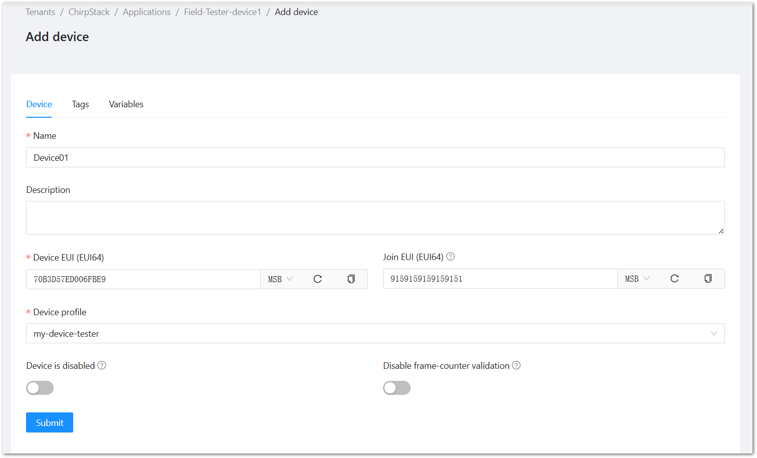 Figure 1: ChirpStack Fill Device Information
- The next step is to provide the Application Key. Use the key provided with the device, if available; otherwise, click the Generate button to create one. After entering the Application Key, click Submit to proceed.
 Figure 1: ChirpStack Add Application Key
Once registered, the Field Tester Plus will begin sending periodic uplinks to the Chirpstack v4 LNS.
 Figure 1: Sending Periodic Uplinks to ChripStack
The device is currently operating in LinkCheck Mode, as the Field Test Data Processor Extension has not yet been configured. In this mode, the device screen will only display:
- Downlink RSSI/SNR
- Number of responding gateways
 Figure 1: Field Tester Only Displays RSSI and SNR
Next, install and configure the Field Test Data Processor Extension to enable full metric reporting (uplinks, packet loss, CSV export).
Configure Field Test Data Processor Extension for ChirpStack v4
For detailed steps on configuring the Field Test Data Processor Extension for the ChirpStack v4, refer to the WisGateOS 2 Extension > Field Test Data Processor > ChirpStack v4.
AWS IoT Core for LoRaWAN
Connect Gateway to AWS IoT Core for LoRaWAN
This section explains how to connect and configure WisGateOS 2 with AWS IoT Core, using the RAK7289V2 model as a reference.
Make sure the frequency band configured on the gateway matches the LoRaWAN Band setting of your Field Tester Plus.
To complete the AWS IoT Core gateway setup, follow the instructions in RAK7289V2 LoRaWAN Network Server Guide | AWS IoT Core .
Register Field Tester Plus on AWS IoT Core for LoRaWAN
Create a destination role for AWS IoT Core for LoRaWAN
To allow AWS IoT Core for LoRaWAN to forward device data to AWS services (via Destinations), you must assign an IAM role and policy that authorizes the service to publish messages on your behalf. If you've already created this IAM role during gateway setup, there's no need to create it again. Otherwise, follow the official AWS instructions below to set it up: Create a destination role for AWS IoT Core for LoRaWAN
Verify Profiles
- Navigate to the AWS IoT console.
- In the navigation pane, go to LPWAN Devices > Profiles.
- Under Device Profiles, review the pre-defined options.
- If none fit your device or region, click Add device profile and configure custom parameters.
- Example: For AS923-1, set parameters accordingly.
 Figure 1: AWS Add Device Profile
- Click Add device profile to save.
- In the Service Profiles section, click Add service profile and configure service parameters (default values are generally acceptable).
 Figure 1: AWS Add Service Profile
- Once you have created appropriate Device and Service Profiles, proceed to set up a destination for device traffic.
Set Up a Destination for Device Traffic
To use the Field Tester Extension with AWS IoT Core for LoRaWAN, you must associate your device with a Destination—this defines where your uplink data will be sent.
- Navigate to the AWS IoT console.
- In the navigation pane, choose LPWAN devices, and then Destinations.
- Choose Add Destination.
- Fill in the Destination details:
- For the Destination name, enter ProcessFieldTesterUplink. The name can be customized.
- Destination description (optional): Provide a helpful description.
- Select Publish to AWS IoT Core message broker. This allows the uplink messages to be published to an MQTT topic for other applications or services to consume.
- Enter a topic such as RecvFieldTesterUplink.
- In the Permissions section, choose Select an existing service role and select the IAM role you had created earlier, from the drop-down.
- Choose Add Destination. You will see a message Destination added, indicating the destination has been successfully added.
 Figure 1: AWS Add Destination
Register Device
- In the navigation pane, go to LPWAN Devices > Devices.
- Click Add wireless device.
- On the Add Device page:
- Select the LoRaWAN specification version in the drop-down under Wireless device specification.
- Enter the DevEUI.
- Fill in the AppEUI/JoinEUI and AppKey as per your OTAA settings.
- Provide a wireless Device name.
- Under Profiles, select the Device Profile and Service Profile you created earlier.
- Under Destination, choose the one previously created.
 Figure 1: AWS Configure LoRaWAN Device
- Click Next, then Add device to complete registration.
Once registered, the Field Tester Plus will begin sending periodic uplinks to the AWS IoT Core.
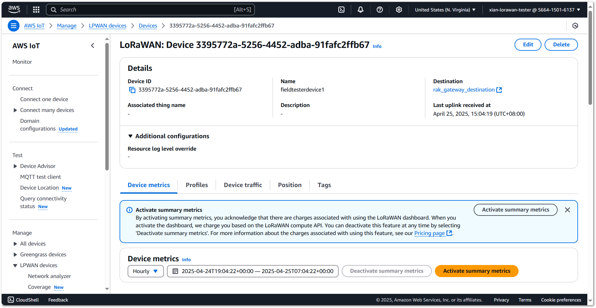 Figure 1: AWS Field Tester Configuration Completed
The device is currently operating in LinkCheck Mode, as the Field Test Data Processor Extension has not yet been configured. In this mode, the device screen will only display:
- Downlink RSSI/SNR
- Number of responding gateways
Figure 1: Field Tester Only Displays RSSI and SNRNext, install and configure the Field Test Data Processor Extension to enable full metric reporting (uplinks, packet loss, CSV export).
Configure Field Test Data Processor Extension for AWS
For detailed steps on configuring the Field Test Data Processor Extension for the AWS IoT Core, refer to the WisGateOS 2 Extension > Field Test > AWS IoT.
The Things Industries (TTI)
Connect Gateway to TTI
This section explains how to connect and configure a RAK gateway with The Things Industries (TTI), using the RAK7289V2 model as a reference.
Make sure the frequency band configured on the gateway matches the LoRaWAN Band setting of your Field Tester Plus.
- Log in to your organization’s TTS Console.
 Figure 1: TTI Login page
- To register a gateway, go to Gateways > + Register gateway.
 Figure 1: Register gateway on TTI
- You will be redirected to the Register gateway page.
- In the Gateway EUI field, type the EUI of the gateway.
- Check the label on the device casing marked as GWEUI.
- Optionally, log in to the gateway's Web UI and navigate to Dashboard > Overview.
 Figure 1: Type EUI of the gateway on TTI
- After typing the EUI, click on Confirm. Additional fields will pop up. Fill in the following information:
 Figure 1: Confirm EUI
- Gateway ID: The unique ID of your gateway in the Network. The ID must contain only lowercase letters, numbers, and dashes (-).
- Gateway name: Optionally, you can type a name for your gateway.
- Frequency plan: The frequency plan used by the gateway.
The other settings are optional and can be changed to satisfy your requirements. For this tutorial, we will use Australia 915-928 MHz, FSB 2 (used by TTN).
- To register your gateway, click Register gateway.
 Figure 1: Register gateway
-
TTNv3 supports TLS server authentication and Client token, which requires a trust file and a key file to configure the gateway to successfully connect it to the network. To generate a key file, from the Overview page of the registered gateway navigate to API keys.https://console.cloud.thethings.network/
-
On the API keys page, choose + Add API key.
 Figure 1: Click Add API key
- In the Name field, type the name of your key (for example - mykey). Choose Grant individual rights and select Link as Gateway to a Gateway for traffic exchange, i.e. write uplink and read downlink.
 Figure 1: Choose Grant individual rights
- To generate the key, choose Create API key. The following window will pop up, telling you to copy the key you just generated.
 Figure 1: Click on Create API key
Copy the key and save it in a .txt file (or other), because you won’t be able to view or copy your key after that.
- Click I have copied the key to proceed.
- To configure the gateway, access it via the Web UI. Navigate to LoRa > Configuration > Work mode and select Basics station.
 Figure 1: Configure gateway
- Expand the Basics Station settings by clicking Configure Basics Station server setup and configure the following parameters:
 Figure 1: Configure Basics Station server setup
- Basics Station Server Type: For server type, choose LNS Server.
- Server URL: You can find it in The Things Stack (TTS) Console, under your registered gateway’s left-hand menu > General settings > Gateway Server address.
NOTE
Make sure to add wss:// in front of the address when entering it into your gateway configuration.
- Server Port: The LNS Server uses port 8887.
- Authentication Mode: Choose TLS server authentication and Client token. When selected, the Trust (CA Certificate) and Client token fields will show up.
- Trust (CA Certificate): For Trust, upload the Let’s Encrypt ISRG ROOT X1 Trust certificate by clicking choose file. The file with the certificate can be downloaded directly.
- Client Token: This is the generated API key.
- To save the changes, click Save Changes.
If everything is set correctly, you can see the gateway is connected to TTNv3.
 Figure 1: Save changes
Register Field Tester Plus on TTI
- Log in to your organization’s TTS Console.
Figure 1: The Things Stack Login page- To create an application, go to Applications > + Add application.
Figure 1: Create an application- Add Application ID, Application name and Description then click Create application.
Figure 1: Register gateway- Click Register end device within your newly created application.
Figure 1: Register end device- Choose Enter end device specifics manually. This will allow you to add the Frequency plan, LoRaWAN version, Regional Parameters version and JoinEUI. The values of these parameters depend on the hardware you use. If your device has a preconfigured JoinEUI, you must use it. Click Confirm after putting all the details.
 Figure 1: Enter end device specifics
- After confirming the JoinEUI, you can proceed on adding other OTAA parameters – DevEUI and AppKey. You can use the Generate button if these parameters are not provided in the device. Else, you must use OTAA parameters are provided in the device.
 Figure 1: Add OTAA parameters
- After you register the device, it will be added on the LoRaWAN Application. Restart the Field Tester Plus and it will join the network and begin sending regular uplinks.
 Figure 1: Regular Uplinks
Once registered, the Field Tester Plus will begin sending periodic uplinks to the TTN LNS.
 Figure 1: Periodic Uplinks
The device is currently operating in ****, as the Field Test Data Processor Extension has not yet been configured. In this mode, the device screen will only display:
- Downlink RSSI/SNR
- Number of responding gateways
 Figure 1: Field Tester LinkCheck Mode
Next, install and configure the Field Test Data Processor Extension to enable full metric reporting (uplinks, packet loss, CSV export).
Configure Field Test Data Processor Extension for TTI
For detailed steps on configuring the Field Test Data Processor Extension for the TTI, refer to the WisGateOS 2 Extension > Field Test Data Processor > TTI.