RAK7246G WisGate Developer D0 Gateway Datasheet
Overview
Description
The RAK7246G is an LPWAN Developer Gateway with a GPS function. It is a device composed of a RAK2246 Pi HAT LPWAN Concentrator module and a Raspberry Pi Zero W.
The RAK2246 Pi HAT is based on a Semtech SX1308 chip, which allows for simultaneous reception over 8 LoRa channels, which cover the entirety of the international high-frequency LoRaWAN space.
The RAK7246G Developer is an ideal choice for prototype design, concept verification and demonstrations, development evaluation, and other scenarios. It is developer-friendly due to its minimalistic design that reduces cost and allows for easily accessing the internals. It is easy to set up, which makes it a good choice for both experienced and novice LoRa specialists.
Features
- Uses an SX1308 baseband processor with dual SX1257, full 8 uplink channels, and 1 downlink channel gateway
- Built-in Ublox MAX-7Q GPS module
- The pre-installed radiator guarantees the stable thermal performance
- Tx max 20 dBm, Rx min -139 dBm @ SF12, BW 125 kHz
- Covers the entirety of the LoRa high-frequency band space: RU864, IN865, EU868, US915, AU915, KR920, AS923
- Power supply 5 V / 2.5 A (power adapter sold separately)
Specifications
Overview
The overview covers the RAK7246G board overview and the block diagram that shows how the components operate.
Board Overview
 Figure 1: uFL Connectors for LoRa and GPS
The interfaces of the RAK7246G are shown in Figure 2. The TF card slot is used for the SD card that houses the firmware (based on Raspbian OS). You have two SMA connectors for the LoRa and GPS antennas. There are 3 ports on the side, which are part of the Raspberry Pi Zero W board, which from left to right are mini HDMI, USB MicroB, and another USB MicroB/Power (only use this to power the device with the included adapter or an equivalent one).
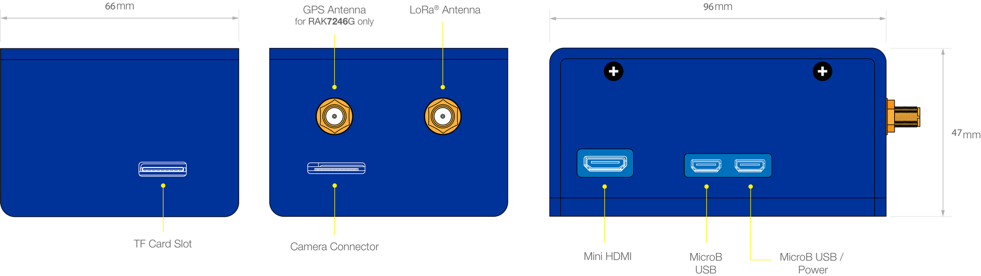 Figure 1: Hardware interfaces
Board Dimensions
Both the RAK2246 and Raspberry Pi have the same board dimensions: 30 x 65 mm. As for the size of the gateway with the casing, refer to Figure 3.
 Figure 1: Casing dimension
Block Diagram
RAK2246 Concentrator
The concentrator is available with an SPI interface:
 Figure 1: RAK2246 bottom view
SX1308
The RAK2246 includes Semtech’s SX1308, which is a digital baseband chip including a massive digital signal processing engine specifically designed to offer breakthrough gateway capabilities in the worldwide ISM band.
The SX1308 is a smart baseband processor for long-range ISM communication. In the receiver part, it receives I and Q digitized bit stream from one or two receivers (SX1257), demodulates these signals using several demodulators, adapts the demodulators settings to the received signal, and stores the received demodulated packets in a FIFO to be retrieved by a host system (PC, MCU). In the transmitter part, the packets are modulated using a programmable (G)FSK/LoRa modulator and sent to one transmitter (SX1257). Received packets can be timestamped using a GPS PPS input.
The SX1308 has an internal control block that receives microcode from the host system (PC, MCU). The microcode is provided by Semtech as a binary file to load into the SX1308 at power-on (see Semtech application support for more information).
The control of the SX1308 by the host system (PC, MCU) is made using a Hardware Abstraction Layer (HAL). The Hardware Abstraction Layer source code is provided by Semtech and can be adapted by the host system developers.
It is highly recommended to utilize the latest HAL as provided by Semtech on https://github.com/Lora-net.
 Figure 1: SX1308 block diagram
The SX1308 digital baseband chip contains 10 programmable reception paths. Those paths have differentiated levels of programmability and allow for different use cases. It is important to understand the differences between those demodulation paths to make the best possible use of the system.
IF8 LoRa channel
This channel is connected to one SX1257 using any arbitrary intermediate frequency within the allowed range. This channel is LoRa only. The demodulation bandwidth can be configured to be 125, 250, or 500 kHz. The data rate can be configured to any of the LoRa available data rates (SF7 to SF12), but as opposed to the IF0 to IF7 channels, only the configured data rate will be demodulated. This channel is intended to serve as a high-speed backhaul link to other gateways or infrastructure equipment. This demodulation path is compatible with the signal transmitted by the SX1272 and SX1276 chip families.
IF9 (G)FSK channel
The IF9 channel is connected to a (G)FSK demodulator. The channel bandwidth and bit rate can be adjusted. This demodulator offers a very high level of configurability, going well beyond the scope of this document. The demodulator characteristics are essentially the same as the (G)FSK demodulator implemented in the SX1232 and SX1272 Semtech chips. This demodulation path can demodulate any legacy FSK or GFSK formatted signal.
IF0 to IF7 LoRa channels
These channels are connected to one SX1257. The channel bandwidth is 125 kHz and cannot be modified or configured. Each channel’s IF frequency can be individually configured. On each of these channels, any data rate can be received without prior configuration.
Several packets using different data rates (different SF) may be demodulated simultaneously even on the same channel. Those channels are intended to be used for a massive asynchronous star network of thousands of sensor nodes. Each sensor may use a random channel (from IF0 to IF7) and a different data rate for any transmission.
Sensors located near the gateway will typically use the highest possible data rate in the fixed 125 kHz channel bandwidth (e.g. 6 kbit/s) while sensors located far away will use a lower data rate down to 300 bit/s (the minimum LoRa data rate in a 125 kHz channel).
The SX1308 digital baseband chip scans the 8 channels (IF0 to IF7) for preambles of all data rates at all times.
The chip can demodulate simultaneously up to 8 packets. Any combination of spreading factor and intermediate frequency for up to 8 packets is possible (e.g. one SF7 packet on IF0, one SF12 packet on IF7 and one SF9 packet on IF1 simultaneously).
The SX1308 can detect simultaneously preambles corresponding to all data rates on all IF0 to IF7 channels. However, it cannot demodulate more than 8 packets simultaneously. This is because the SX1308's architecture separates the preamble detection and signal acquisition task from the demodulation process. The number of simultaneously demodulated packets (in this case 8) is an arbitrary system parameter and may be set to other values for a customer-specific circuit.
The unique multi-data-rate multi-channel demodulation capacity SF7 to SF12 and of channels IF0 to IF7 allows innovative network architectures to be implemented.
 Figure 1: LoRa Channel
Hardware
The hardware specification is categorized into four parts. It includes the interfacing, pinouts, and their corresponding functionalities and diagram. It also presents the features of RAK7246G and its parameters.
Interfaces
External Module Interfaces
SPI
The pins on the connector provide an SPI connection, which allows direct access to the SX1308 SPI interface. This gives the target system the possibility to use existing SPI interfaces to communicate.
After powering up RAK2246, it is required to reset SX1308 via pin 11.
UART and I2C
The pins on the bottom side provide a UART connection and I2C connection, which allow direct access to the GPS module. The 1PPS has been connected to the SX1308 internally.
Digital IOs
There are two digital IO pins, which give the user an interface to reset the GPS module or set it into standby mode.
Pin Definition
 Figure 1: RAK7246G Pinout Diagram
| Pin | Name | Description |
|---|---|---|
| 1 | NC | Not Connected |
| 2 | +5V | +5V Supply Voltage |
| 3 | SDA | I2C_SDA (Connected to GPS Module I2C_SDA) |
| 4 | +5V | +5V Supply Voltage |
| 5 | SCL | I2C_SCL (Connected to GPS Module I2C_SCL) |
| 6 | GND | Ground |
| 7 | NC | Not Connected |
| 8 | UART_TX | It should be connected to the RPi’s UART_TXD. It is connected to the GPS Module’s UART_RXD internally. |
| 9 | GND | Ground |
| 10 | UART_RX | It should be connected to the RPi’s UART_RXD. It is connected to the GPS Module’s UART_TXD internally. |
| 11 | RESET | SX1308 RESET (GPIO17 of RPi) |
| 12 | NC | Not Connected |
| 13 | NC | Not Connected |
| 14 | GND | Ground |
| 15 | NC | Not Connected |
| 16 | NC | Not Connected |
| 17 | NC | Not Connected |
| 18 | NC | Not Connected |
| 19 | SPI_MOSI | It should be connected to the RPi’s SPI_MOSI. It is connected to the SX1308’s SPI_MOSI internally. |
| 20 | GND | Ground |
| 21 | SPI_MISO | It should be connected to the RPi’s SPI_MISO. It is connected to the SX1308’s SPI_MISO internally |
| 22 | NC | Not Connected |
| 23 | SPI_SCLK | It should be connected to the RPi’s SPI_SCLK. It is connected to the SX1308’s SPI_CLK internally. |
| 24 | SPI_CE0 | It should be connected to the RPi’s SPI_CE0. It is connected to the SX1308’s SPI_CS internally. |
| 25 | GND | Ground |
| 26 | NC | Not Connected |
| 27 | ID_SD | I2C_SDA for HAT ID EEPROM |
| 28 | ID_SC | I2C_SCL for HAT ID EEPROM |
| 29 | NC | Not Connected |
| 30 | NC | Not Connected |
| 31 | NC | Not Connected |
| 32 | NC | Not Connected |
| 33 | RESET_GPS | GPS Module reset pin (GPIO13 of RPi) |
| 34 | GND | Ground |
| 35 | STANDBY_GPS | GPS Module standby pin (GPIO19 of RPi) |
| 36 | NC | Not Connected |
| 37 | NC | Not Connected |
| 38 | NC | Not Connected |
| 39 | GND | Ground |
| 40 | NC | Not Connected |
Main Specifications
The following table shows the available features of the RAK7246G WisGate Developer D0 Gateway and its corresponding specifications:
| Feature | Specifications |
|---|---|
| Computing | • Raspberry Pi Zero Wireless (BCM2835, ARMv7) • Memory: 512MB • Storage: SD card slot |
| WiFi Feature | • Frequency: 2.400-2.4835 GHz (802.11b/g/n) • RX Sensitivity: -99 dBm • TX Power: 21 dBm |
| LoRa Feature | • RAK2246 LoRaWAN Concentrator • Semtech SX1308 with dual SX1257 • Up to 8 uplink and 1 downlink channels • RX Sensitivity: -139 dBm • TX Power: 20 dBm (Max) • Frequency bands supported: RU864 / IN865 / EU868 / US915 / AU915 / KR920 / AS923 |
| Power Supply | • DC 5V / 2.5 A |
| Power Consumption | • 5 W (average) |
| Antennas | • LoRa: RP-SMA Female Connector • GPS: SMA Female • WiFi: Internal Antenna |
| LEDs | • POWER/STATUS LED |
| Ingress Protection | • IP30 |
| Enclosure Material | • Plastic |
| Weight | • 300 g |
| Dimension | • 96 mm x 66 mm x 47 mm |
| Operating Temperature | • -10˚ C to 65˚ C |
RF Characteristics
LoRa
| Feature | Specifications |
|---|---|
| Operating Frequency | • EU433, CN470, EU868, US915 • AS923, AU915, KR920, IN865 |
| Transmit Power | 27 dBm (Max) |
| Receiver Sensitivity | -142 dBm (Min) |
Transmitter RF
The RAK2246 has excellent transmitter performance. It is highly recommended to use an optimized configuration for the power level configuration, which is part of the HAL. This results in a mean RF output power level and current consumption:
| MIX Control | DIG Gain | Nominal RF Power Level (dBm) |
|---|---|---|
| 8 | 0 | 10 |
| 9 | 0 | 12 |
| 10 | 0 | 14 |
| 11 | 0 | 16 |
| 12 | 0 | 18 |
| 13 | 0 | 19 |
| 14 | 0 | 20 |
| 15 | 0 | 21 |
T=25° C, VDD=5 V (Typ.) if nothing else stated
| Parameter | Condition | Min | Typ. | Max | Unit |
|---|---|---|---|---|---|
| Frequency Range | 863 | 870 | MHz | ||
| Modulation Techniques | FSK/LoRa | ||||
| TX Frequency Variation vs. Temperature | Power Level Setting: 20 dBm | -3 | +3 | kHz | |
| [TX Power Variation](TX Power Variation) vs. Temperature | -5 | +5 | dB | ||
| TX Power Variation | -1.5 | +1.5 | dB |
Also supports the 915 Frequency Range.
Receiver RF
It is highly recommended, to use optimized RSSI calibration values, which is part of the HAL v3.1. For both, Radio 1 and Radio 2, the RSSI-Offset should be set to -169.0. (It is highly recommended, to use optimized RSSI calibration values, which is part of the HAL v3.1. For both, Radio 1 and Radio 2, the RSSI-Offset should be set to -169.0. )
The following table gives typical sensitivity level of the RAK2246:
| Signal Bandwidth (kHz) | Spreading Factor | Sensitivity (dBm) |
|---|---|---|
| 125 | 12 | -141 |
| 125 | 7 | -128 |
| 250 | 12 | -137 |
| 250 | 7 | -124 |
| 500 | 12 | -135 |
| 500 | 7 | -121 |
RF Key Components
This section introduces the key components in the RAK2246 to help developers to utilize the system to its fullest in their designs.
1. DC-DC regulator
The system power supply is provided by an external 5 VDC power supply. All the key components and related clock crystals are powered by two DC-DC regulators (MP1496) which output 1.8 V and 3.3 V to meet normal working conditions. The MP1496 is a high-frequency, synchronous, rectified, step-down, switch-mode converter with built-in power MOSFETs. It offers a very compact solution to achieve a 2 A continuous output current with excellent load and line regulation over a wide input supply range.
2. FEM
The FEM chosen is a SKYWORKS SKY66422, which integrates a PA, LNA, and a switch. It can achieve a 20 dBm max output power to deliver sufficient RX performance. The frequency range it can cover is 860 MHZ ~ 930 MHz.
 Figure 1: System Architecture
Wi-Fi
| Features | Specifications |
|---|---|
| Wireless Standard | IEEE 802.11b/g/n |
| Operating Frequency | ISM band: 2.412~2.472(GHz) |
| Operation Channels | 2.4 GHz: 1-13 |
| Transmit Power (The max. power may be different depending on local regulations) -per chain | - 802.11b - @1 Mbps : 19 dBm, @11 Mbps : 19 dBm - 802.11g - @6 Mbps : 18 dBm, @54 Mbps : 16 dBm - 802.11n (2.4G) - @MCS0 (HT20) : 18 dBm, @MCS7 (HT20) : 16 dBm,@MCS0 (HT40) : 17 dBm, @MCS7 (HT40) :15 dBm |
| Receiver Sensitivity (Typical) | - 802.11b - @1Mbps : -95 dBm, @11Mbps : -88 dBm - 802.11g - @6Mbps : -90 dBm, @54 Mbps : -75 dBm - 802.11n (2.4G) - @MCS0 (HT20) : -89 dBm, @MCS7(HT20) : -72 dBm,@MCS0(HT40) : -86 dBm, @MCS7(HT40) : -68 dBm |
Software
Software Specifications
| LoRa | Network | Management |
|---|---|---|
| Class A & C | Wi-Fi AP/Client mode | SSH2 |
| LoRa package forwarder | DHCP Client | - |
| Country code setup | - | - |
| TX power setup | - | - |
| Location setup | - | - |
| Supports server address & port setup | - | - |
LoRaWAN Systems, Network Approach
LoRaWAN technology has “Public” and “Private” networks. In both cases, the usage of a concentrator module is a must if a multichannel performance is required. Public networks are operator-managed (e.g. telecom companies) networks, whereas private networks are individually managed networks.
LoRaWAN networks are typically star or multiple-star networks, where a gateway relays the packets between the end-nodes and a central network server. For private network approaches, the server can also be implemented on the gateway host.
Due to the long-range, LoRa provides the connection between the end-nodes and the gateway (RAK2246) is always a direct link. Repeaters are not common in a LoRaWAN network.
Depending on the used spreading factor and signal bandwidth, different data rates (0.3 kbps to ~22 kbps) and sensitivities down to -142.5 dBm are possible. Spreading factor and signal bandwidth are a trade-off between data rate and communication range.
Overview
The RAK2246 can receive on different frequency channels at the same time and can demodulate the LoRa signal without knowledge of the used spreading factor of the sending node. Thus, any gateway using it as its concentrator module has these inherent benefits as well.
 Figure 1: System Architecture
Because the combination of spreading factors and signal bandwidths results in different data rates, the use of “Dynamic Data-Rate Adaption” becomes possible. That means that LoRa nodes a large distance away from the gateway can use higher spreading factors and therefore have a lower data rate. LoRa nodes that are closer to the concentrator can use lower spreading factors and therefore can increase their data rate.
Since spreading factors are orthogonal and the RAK2246 Concentrator can demodulate on 8 channels at the same time, the channel capacity of a LoRaWAN gateway is increased compared to traditional cellular networks.
Firmware
The LoRa MAC specification is currently driven by the companies Semtech, IBM, and Actility. Currently, all available software, firmware, and documentation can be found and downloaded from the open-source project LoRa-net hosted on https://github.com/Lora-net.
This project hosts all parts that are needed to run a network based on LoRa technology. It includes the node firmware (several hardware platforms are supported), the gateway host software (HAL driver for SX1308, packet forwarder), and server implementation.
It is highly recommended to utilize the latest HAL as provided by Semtech.
Firmware Specification
Download the latest firmware of RAK7246G in the table provided below. The supported software features are also included with the standard parameters.
| Model | Raspberry Pi Board | Firmware Version | Source |
|---|---|---|---|
| RAK7246 | Raspberry Pi Zero W | 4.2.0R | Download |
Configuring the Gateway
You can log in to the gateway using an SSH client like PuTTY. For more details on the configuration and management of the gateway, visit the link below:
RAK7246G WisGate Developer D0 Gateway User Manual
Models / Bundles
Order Information
| Part Number | Package | Description |
|---|---|---|
| RAK7246G | 1x LoRa Antenna, 1x GPS Antenna, 1x Micro USB Cable, 1x 16GB TF Card | Supports region: IN865 / EU868 / US915 / AU915 / AS923 / KR920 |