RAK7268V2/RAK7268CV2/RAK7268CV2-V WisGate Edge Lite 2 Quick Start Guide
Log in to the WisGateOS 2 Web UI
Access the Gateway
In this section, two methods of accessing the gateway are provided to offer different alternatives based on the availability of the required resources.
WiFi AP Mode
By default, the gateway will work in Wi-Fi AP Mode which means that you can find an SSID named like RAK7268V2_XXXX, RAK7268CV2_XXXX, or RAK7268CV2-V_XXXX on your PC's Wi-Fi Network List. XXXX is the last two bytes of the Gateway MAC address.
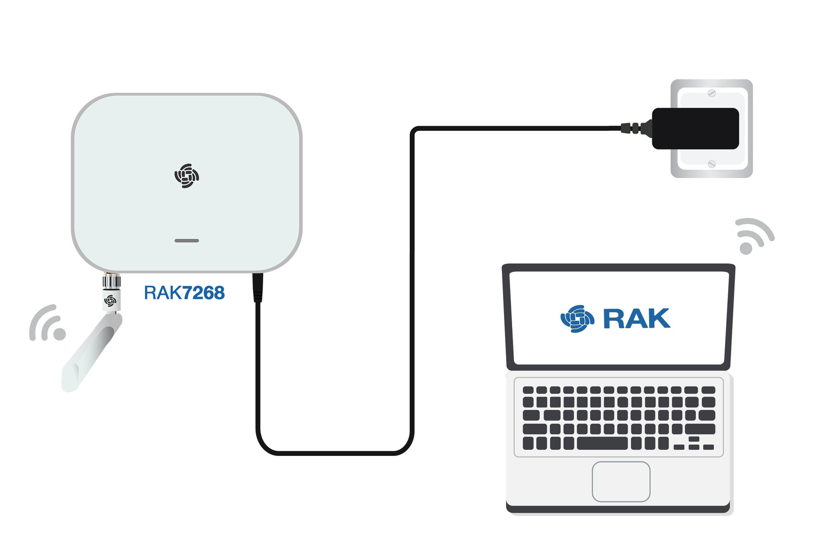 Figure 1: Accessing the gateway via WiFi AP Mode
-
Connect to the gateway’s WiFi.
NOTENo password is required to connect via Wi-Fi AP mode.
-
Open a web browser and enter the IP address:
192.168.230.1
WAN Port (Ethernet)
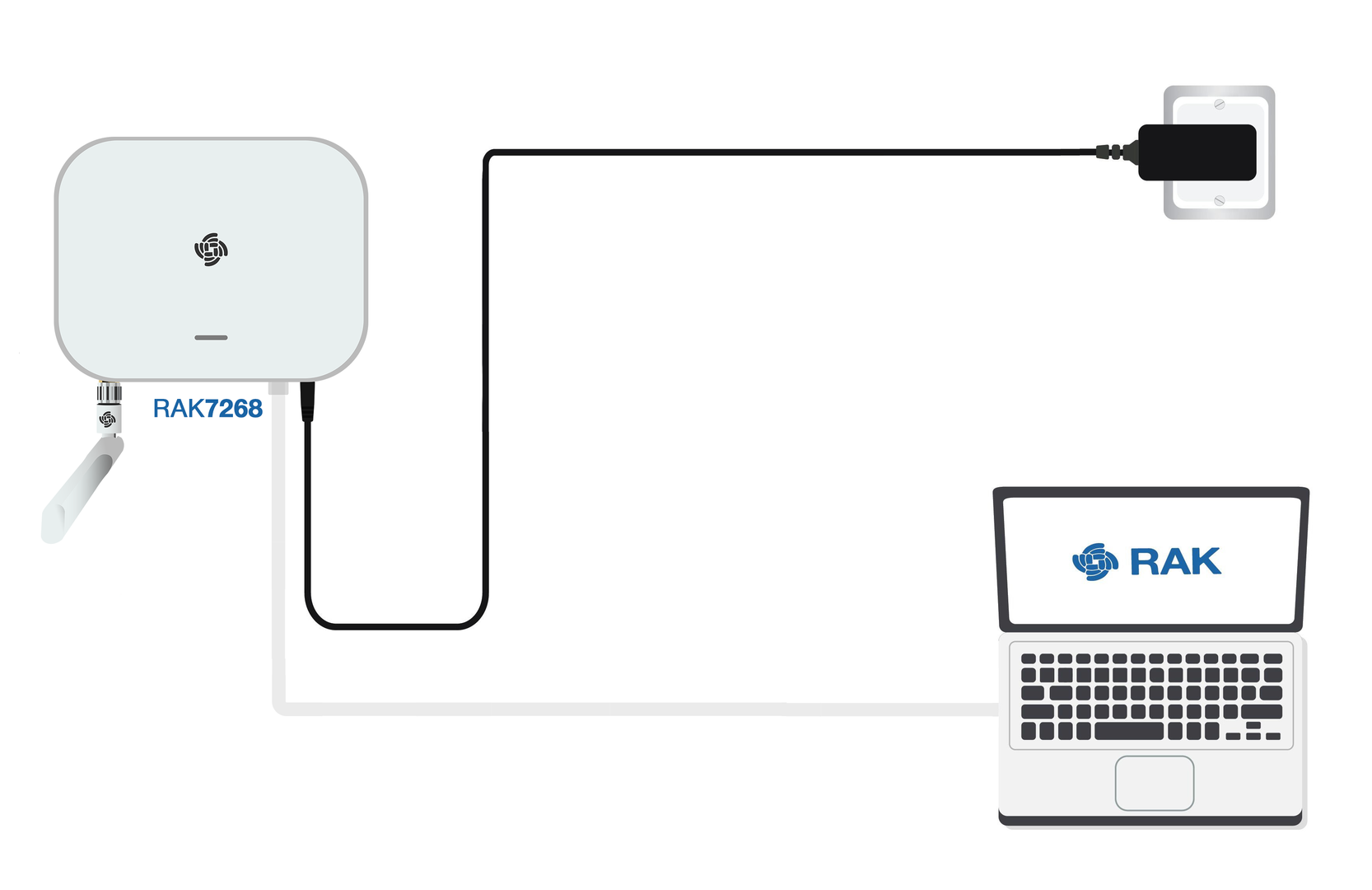 Figure 1: Access the gateway via WAN Port (Ethernet)
- Connect an Ethernet cable from the gateway’s ETH(PoE) port to your PC’s Ethernet port.
- Set a static IP address on your PC in the same subnet as the gateway:
NOTE
The default IP of the gateway is
169.254.X.X, derived from the last 4 bits of the MAC address. For example, if the last 4 bits are0F:01, the gateway IP is169.254.15.1. Set your PC's IP address accordingly, e.g.,169.254.15.100. - Open the Internet Properties of your PC, and select Internet Protocol Version 4 (TCP/IPv4).
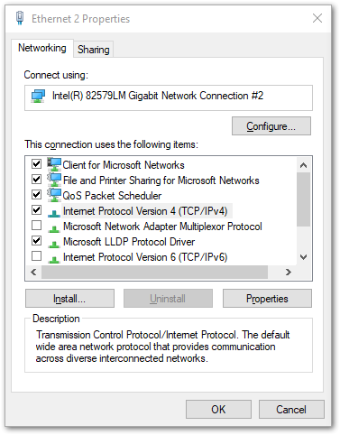 Figure 1: Internet properties
- Select Use the following IP address, and set the PC’s IP address (e.g.,
169.254.15.100). Ensure the PC’s IP address is in the same subnet as the gateway (e.g., if the gateway IP is169.254.15.1, set the PC to169.254.15.100).
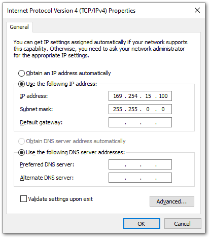 Figure 1: Set IP address of the PC
- Open a web browser and enter the gateway's IP address (e.g.,
169.254.15.1) to access the Web UI. You will be directed to the gateway system login page.
Log in
-
On the first login, you must set a login password. The password must:
- At least 12 characters long
- Has at least one special character (
!“#$%&\‘()*+,-./:;<=>?@[]^_{|}~) - Has at least one number
- Has at least one standard Latin letter (used in the English alphabet)
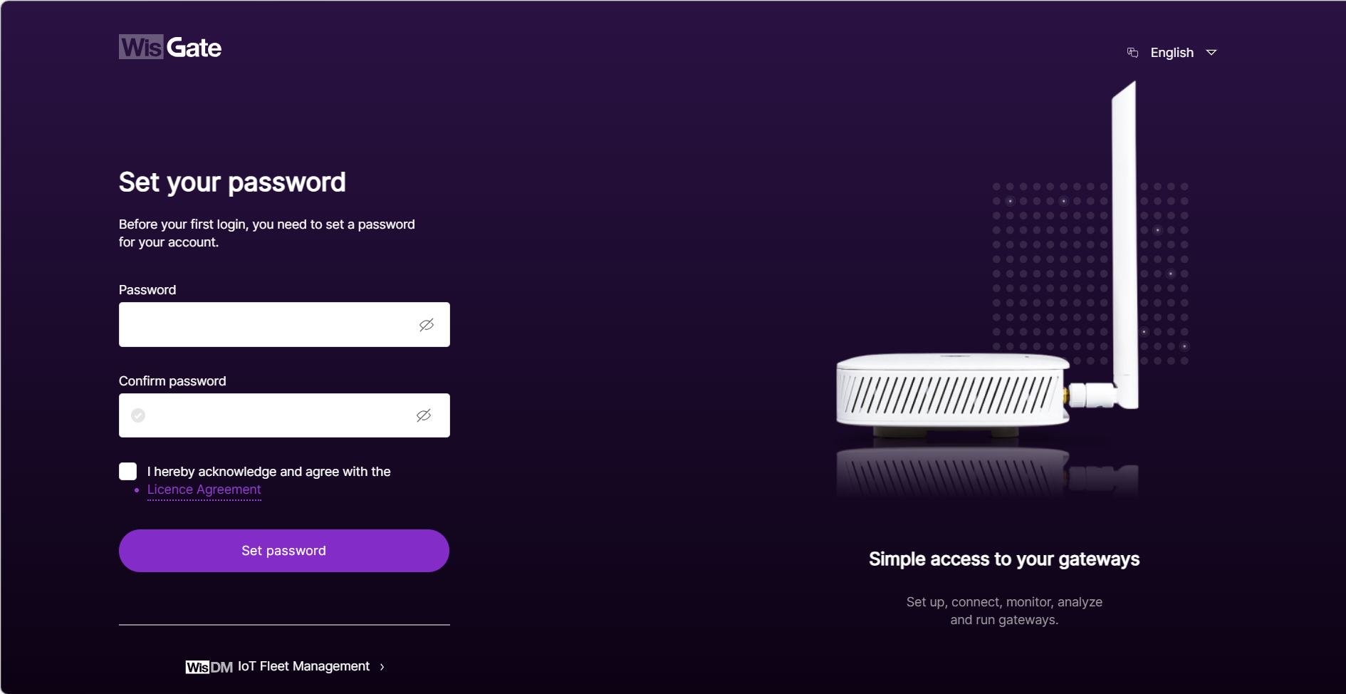 Figure 1: Web UI login page
 -
Check the agreement box to accept the License Agreement before proceeding.
-
Click Set password to continue. You will be redirected to the LoRaWAN Statistics page.
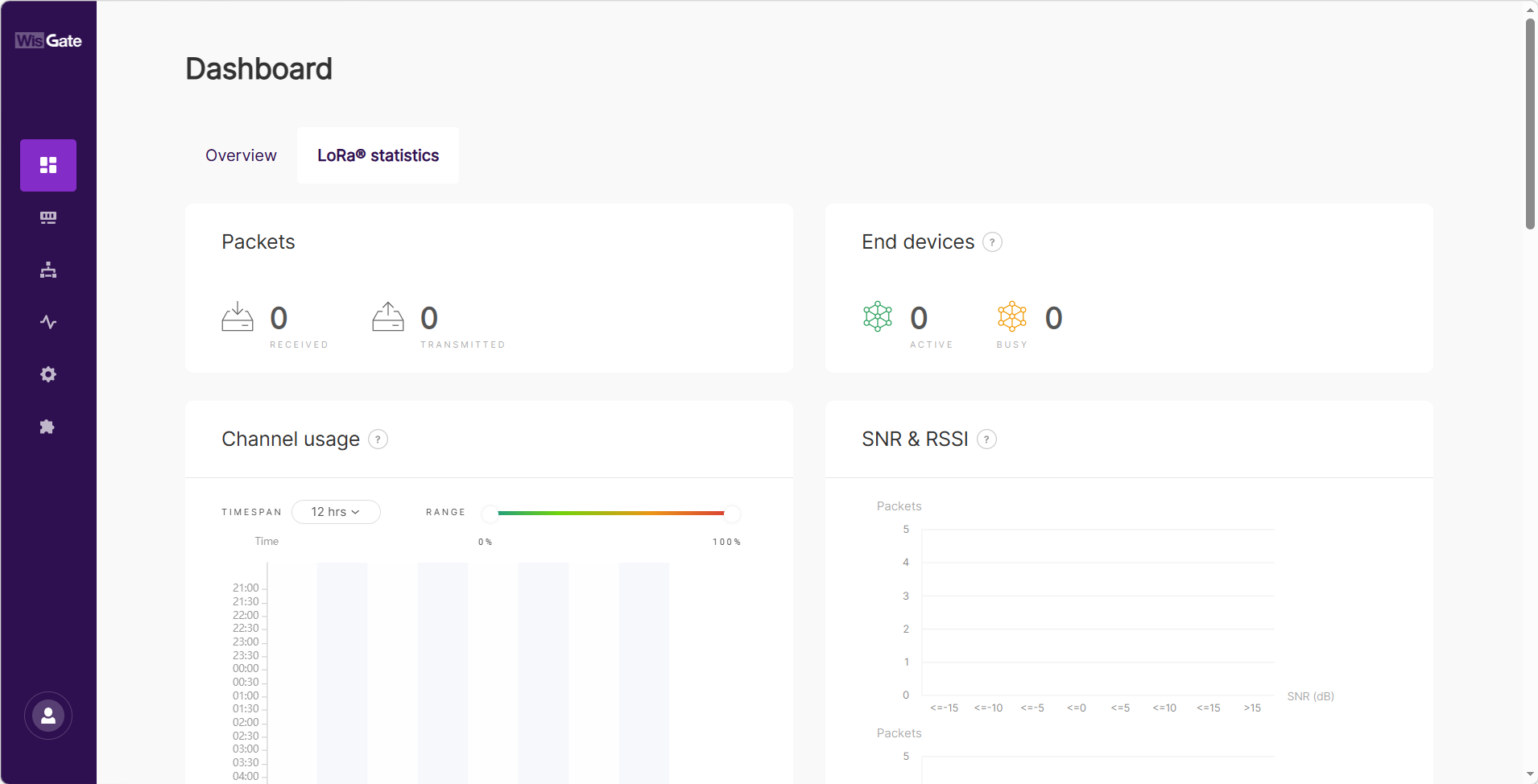 Figure 1: LoRaWAN statistics page
 -
For future logins, use the password you set. The default login username is root.
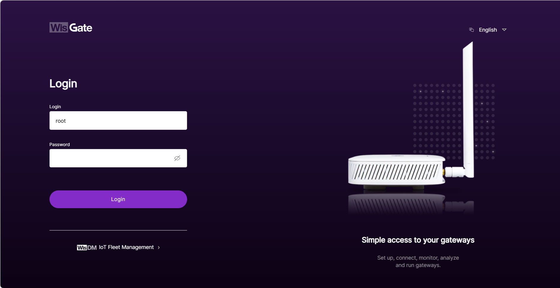 Figure 1: Login Page with set password
Please make sure to save your password securely. If you forget the WisGateOS 2 password, the only way to regain access is to reset the gateway to factory settings. This will erase all configurations.
Access the Internet
You can connect the gateway to the Internet via Wi-Fi, Ethernet, or Cellular (for LTE models). Multiple connection types can be configured at the same time.
The examples in this section use the DC 12V version of the gateway as the reference model.
Wi-Fi
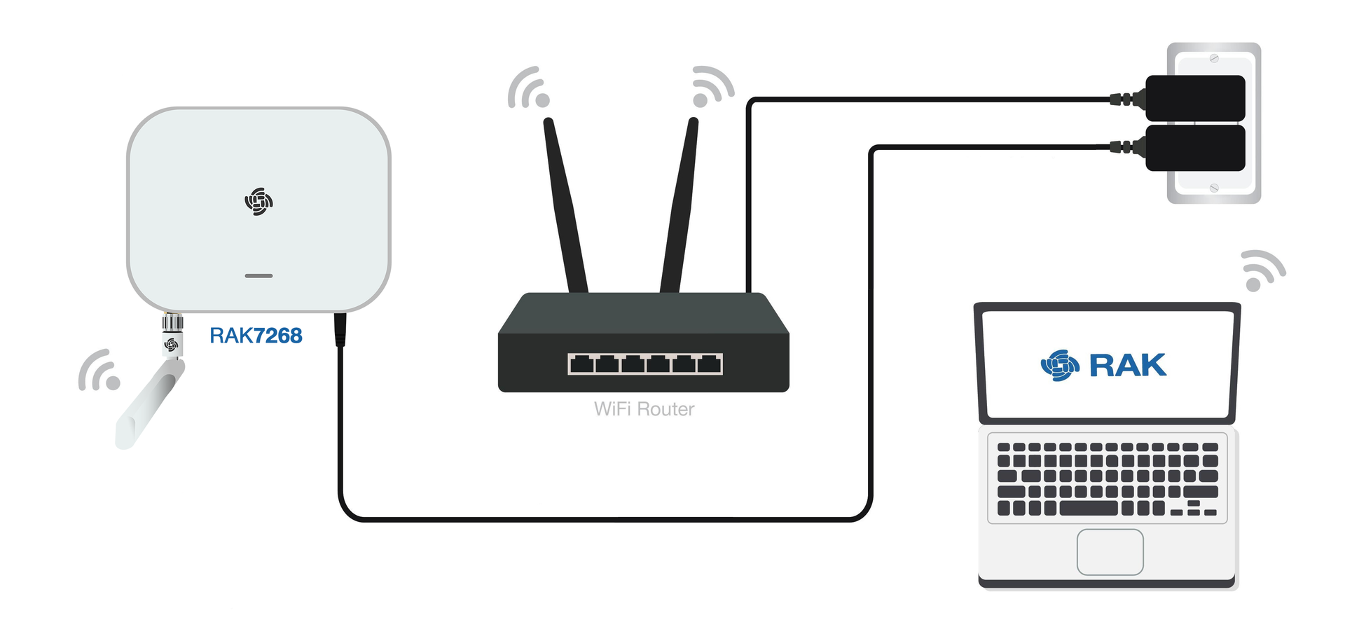 Figure 1: Connect the internet via WiFi
- Log in to the Web UI, go to Network > WAN > Wi-Fi.
- Expand the WiFi section and click on Settings. Ensure the Interface is enabled.
- Click the Scan button to select your ESSID, or manually enter the ESSID of the network by clicking Enter network (E)SSID manually.
- Choose the correct Encryption method and enter the appropriate Key.
NOTE
Assuming you have entered the correct parameter values, you should receive an IP address assigned by your WiFi router's (AP) built-in DHCP server. You can use this new IP address to log in via a web browser.
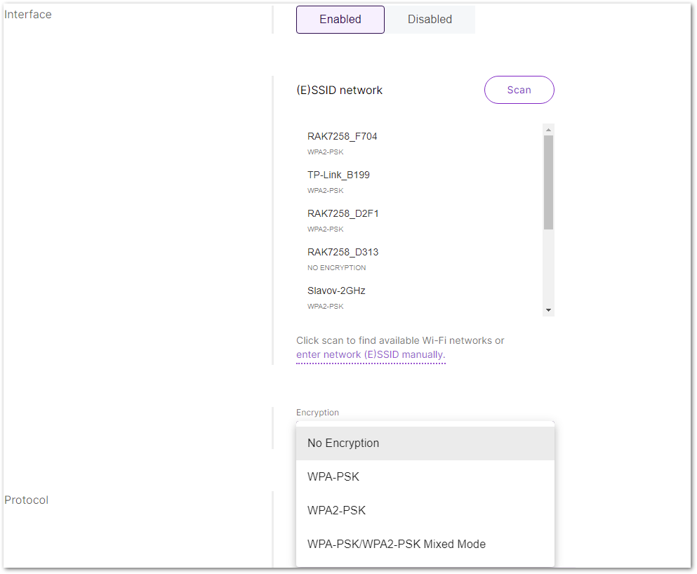 Figure 1: WiFi settings
For details, refer to the WisGateOS 2 User Manual > WAN > Wi-Fi.
Ethernet
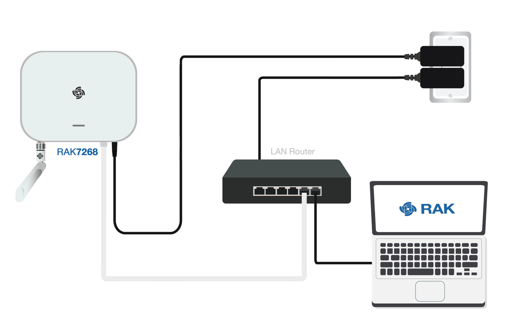 Figure 1: Access the Internet through Ethernet
- Connect one end of an Ethernet cable to the gateway’s ETH(PoE) port, and the other end to your router.
The router's DHCP server will automatically assign an IP address to the gateway. You can use this assigned IP to access the gateway via a web browser.
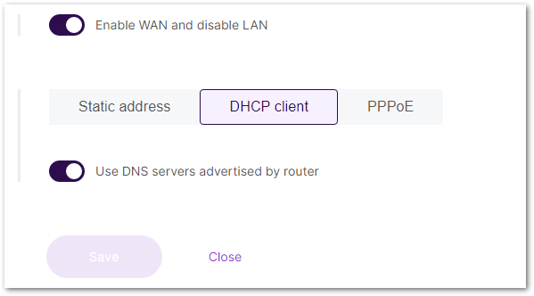 Figure 1: Connect through Ethernet settings
If additional configuration is required, refer to the WisGateOS 2 User Manual > WAN > Ethernet.
LTE (For cellular models)
If you are using the RAK7268CV2 or RAK7268CV2-V model and have inserted a valid SIM card, the gateway will typically connect to the cellular network automatically.
However, in some regions, manual APN configuration may be required depending on your mobile operator.
To manually configure APN and other LTE settings:
- Log in to the Web UI and navigate to Network > WAN > Cellular.
- Expand the Cellular section and click on Settings.
- Enter the required APN, username, password, and PIN code if provided by your mobile operator.
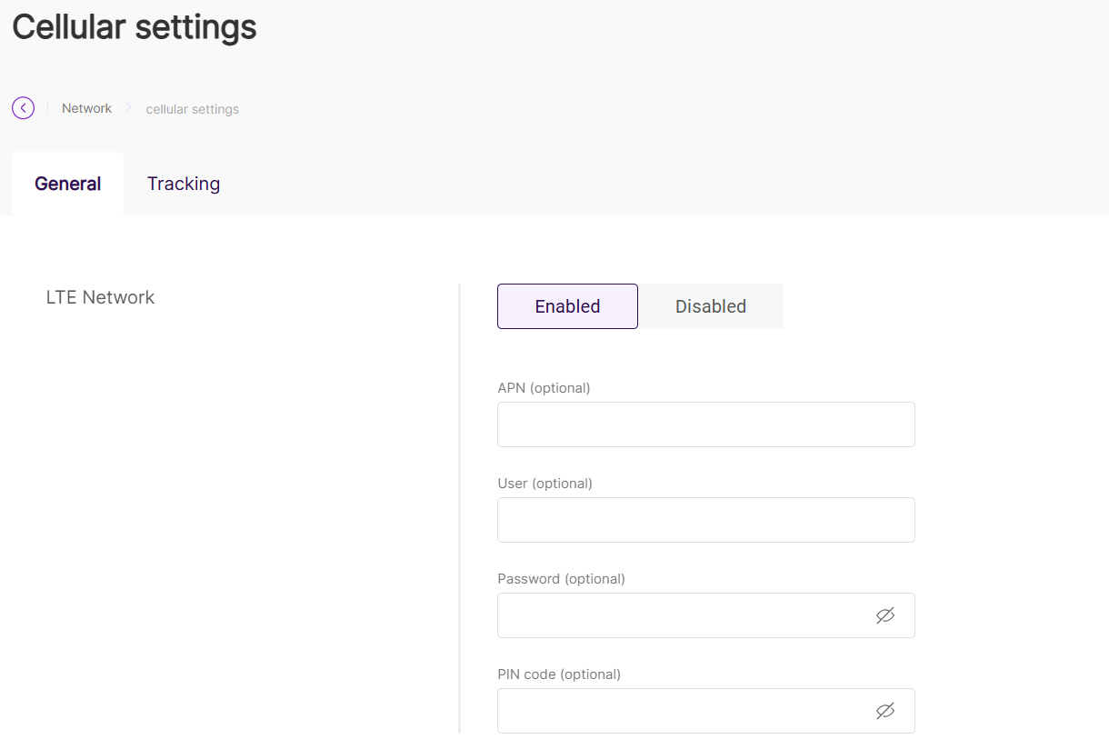 Figure 1: Connect through cellular settings
For details on each parameter, refer to the WisGateOS 2 User Manual > WAN > Cellular.
Make sure that your SIM card is activated and supports data services.
Connect to LoRaWAN® Network Server
Configure your gateway’s work mode to quickly establish a connection with a LoRaWAN® Network Server. The gateway supports three operation modes — Built-in Network Server, Packet Forwarder, and Basics™ Station.
For detailed configuration steps and explanations, refer to the LoRa Configuration Guide.