RAK7285/RAK7285C Unboxing & Installation
For outdoor gateways, RAKwireless recommends completing basic gateway configuration indoors before field installation. This helps verify gateway access, Internet connectivity, SIM card status, and LoRaWAN® server settings before the gateway is permanently installed outdoors.
This guide is organized by setup scenario. You can first choose the scenario that matches your deployment stage, then follow the referenced hardware setup procedures.
Prerequisites
Package Inclusion
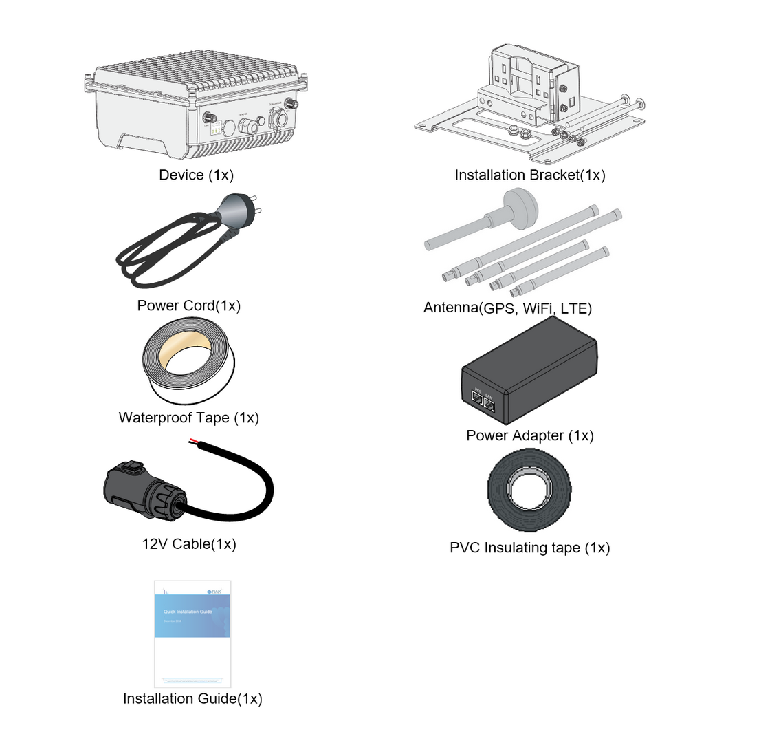 Figure 1: RAK7285/RAK7285C packing list
-
LoRa® antenna is not included and must be purchased separately.
-
LTE antennas are included only with cellular models (RAK7285C).
Additional Hardware Required
-
Ethernet Cable (RJ-45 Port) – Required for network setup
-
A Windows/MacOS/Linux Computer – For configuration via Web UI
-
LoRa® Antenna(s) – One or two antennas may be required, depending on your gateway model
-
NanoSIM Card (for LTE version) – Size: 12 x 9 x 0.67 mm
Installation Workflow
This section describes the recommended installation workflow for outdoor gateway deployments.
Indoor Pre-Configuration
Use this scenario when you want to power on and configure the gateway indoors before installing it outdoors.
During indoor pre-configuration, you can complete the basic hardware setup required for software configuration.
Complete the following sections:
- Insert SIM Card — for cellular models only
- Attach Antennas and Cables
- Power On the Gateway
- Continue with the Quick Start Guide to:
- Access the WisGateOS 2 Web UI
- Configure Internet access through Ethernet, Wi-Fi, or Cellular
- Configure the LoRaWAN® Network Server connection
After the indoor pre-configuration is complete, power off the gateway and continue with outdoor field installation.
Outdoor Field Installation
Use this scenario when the gateway is ready to be permanently installed outdoors.
Outdoor field installation includes mounting the gateway, installing antennas and cables, applying grounding and lightning protection, weatherproofing the connectors, and connecting the final power source.
Complete the following sections:
-
Insert SIM Card — for cellular models only
NOTEIf the SIM card has already been inserted during indoor pre-configuration, you can skip this step for cellular models.
-
Verify gateway status in WisGateOS 2 or WisDM after installation.
Hardware Setup Procedures
Insert SIM Card (For cellular models)
- If the gateway is running WisGateOS 2.3.1 or later, the SIM card slot supports hot-swapping.
- For versions earlier than WisGateOS 2.3.1, the SIM card slot is not hot-swappable. Always power off the gateway before inserting or removing the SIM card.
- Start by unscrewing the cap of the NanoSIM interface on the gateway enclosure to expose the SIM card slot.
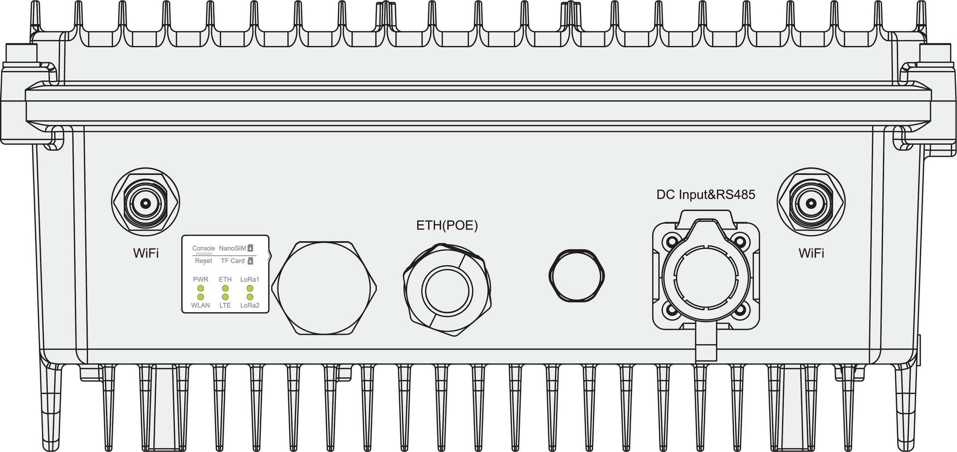 Figure 1: Unscrewing the cap of the NanoSIM interface
- Push the SIM card into the card slot according to the placement method marked on the interface.
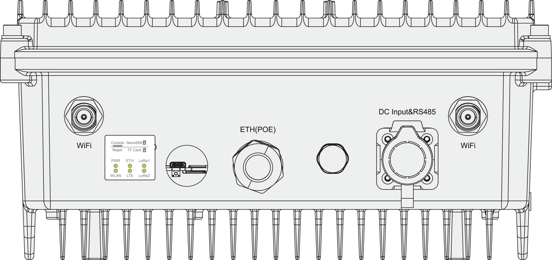 Figure 1: Inserting the NanoSIM card
- Once completed, screw back the metal cap. Make sure it is tightly screwed.
Mount the Gateway
- Attach the mount adapter included in the mounting kit on the bottom of the enclosure using four M6 x 12 mm screws.
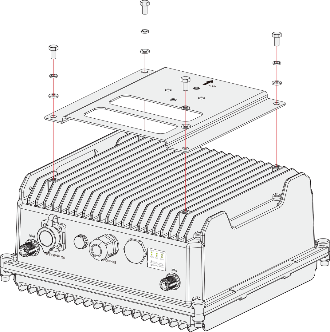 Figure 1: Attaching the mount adapter to the enclosure
- After attaching the mount adapter, fix the device bracket on it with four M6*12 screws.
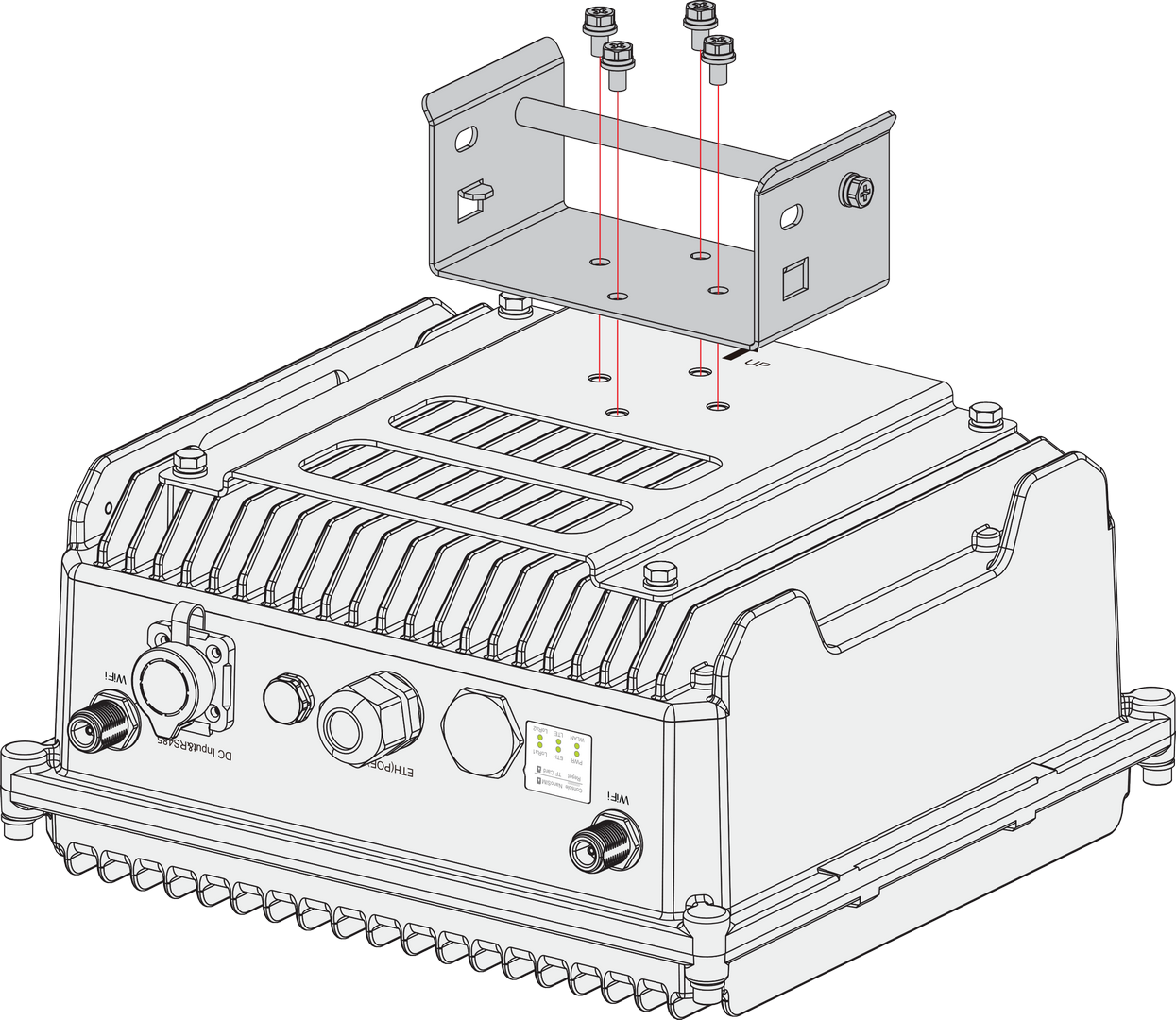 Figure 1: Mounting the device bracket to the enclosure
- Position and fasten the pole clamps together around the pole with bolts, washers, and nuts.
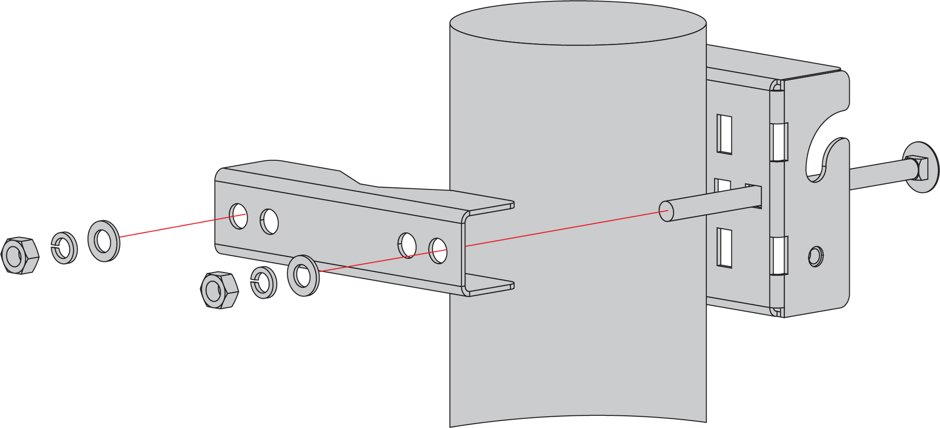 Figure 1: Mounting the clamps to a pole
The pole supported by the brackets has a diameter ranging from 50~100 mm. If the pole diameter exceeds 100 mm, you can use steel strips instead. The standard mounting kit does not include steel strips, they are sold separately.
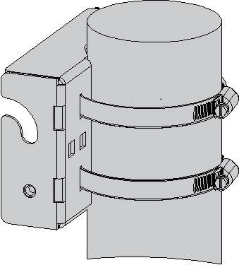 Figure 1: Mounting using steel strips
- Hang up the enclosure and affix it with two M6*12 screws.
 Figure 1: Fastening the enclosure to the bracket
Gateway Grounding and Lightning Protection
Lightning strikes can generate powerful electrical surges that may harm sensitive electronic devices. It is essential to take appropriate precautions to minimize the risk of damage. The warranty provided does not cover damages resulting from lightning strikes or other acts of nature.
For outdoor deployments, protection should cover the gateway enclosure, outdoor GPS/Wi-Fi/LTE antenna connections, and the Ethernet/PoE connection to indoor network devices. The protection system typically includes:
- Gateway grounding: Provides a safe discharge path for electrical surges through the gateway enclosure.
- GPS/Wi-Fi/LTE antenna lightning protection: Protects GPS, Wi-Fi, and LTE antenna connectors from lightning-induced surges.
- Ethernet/PoE surge protection: Protects indoor network devices, such as PoE injectors, switches, or routers, from surges carried through the Ethernet cable.
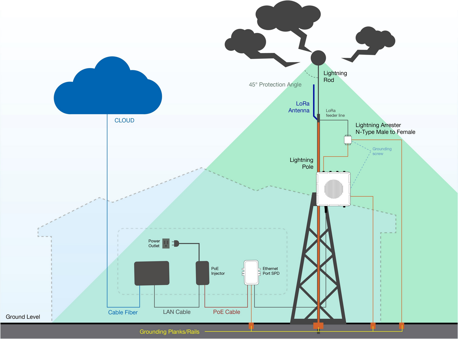 Figure 1: Gateway grounding and lightning protection setup
Gateway Grounding
Gateway grounding connects the gateway enclosure to a reliable grounding point. This helps discharge electrical surges safely and reduces the risk of damage to the gateway and connected equipment.
To ground the gateway:
- Locate the grounding screw on the right side of the gateway casing.
- Use 10 AWG or thicker grounding wire. Connect one end of the grounding wire to the gateway grounding screw.
- Connect the other end to a proper grounding point, such as:
- A grounding rail mounted on the building wall
- A grounding bar in field deployments
- Another qualified protective earth grounding system
Antenna Lightning Protection
GPS, Wi-Fi, and LTE antenna lightning protection helps protect the gateway antenna ports from surge currents induced by lightning or nearby electrical discharge.
For each GPS, Wi-Fi, or LTE antenna connection:
- Install a lightning arrestor on each antenna’s N-type terminal (LoRa®). The arrestors must be N-type Female to Male to match the antenna and gateway interface.
- Use 10 AWG or thicker grounding wire to connect the arrestor grounding terminal to the grounding rail mounted on the building wall or a grounding bar in field deployments.
- Keep the grounding wire as short and straight as possible to reduce surge impedance.
No additional lightning protection is required for the LoRa® antennas. The cavity diplexer integrated into the LoRa® antenna ports provides surge protection for the LoRa® antennas.
Ethernet/PoE Surge Protection
Ethernet/PoE surge protection helps protect indoor network devices connected to the outdoor gateway, such as PoE injectors, switches, and routers.
To protect indoor equipment and circuitry connected to the gateway, it is recommended to install an Ethernet SPD (Surge Protection Device) on the Ethernet cable path between the outdoor gateway and the indoor network equipment.
For Ethernet/PoE protection:
- Install the Ethernet SPD between the gateway and the indoor PoE injector, switch, or router.
- Connect the SPD grounding terminal to a proper building grounding point.
- Make sure the Ethernet cable and SPD are suitable for the required network speed and outdoor deployment conditions.
No additional Ethernet surge protection is required on the gateway side. The gateway already has a built-in surge protection system for the Ethernet connection.
Recommended Equipment
- Lightning Arrestor for GPS Antenna: This lightning arrestor connects the antenna to the GPS receiver. It is a surge protection device that secures the transceiver against transients, over-voltage, and surge currents induced by lightning bolts. By employing a high-pass filter, this product can effectively suppress low-frequency interference caused by lightning while allowing the GPS signal to pass through with low insertion loss. A transient suppression device (TVS) and a gas discharge tube (GDT) are used to protect the DC feed circuit.
- Lightning arrestor for the LTE and Wi-Fi antennas: This is a surge protection device for securing transceivers against over-voltage and surge current induced by lightning bolts. RAKwireless recommends installing lightning arrestors on all N-type antenna terminals, including LTE and 2.4G Wi-Fi antennas.
- Pulsar Cable RAK9731: RAK9731 Pulsar cable is used for RAK7285 Lightning Protection. This cable is an N-Type Male to N-Type Female cable with 1.5 m, 3 m, 5 m, 10 m, or longer custom lengths. It is an LMR-400 coaxial cable with N-type connectors.
- Signal Surge Protective Device: This surge protective device is suitable for CAT6 or Class E cables, providing protection for equipment from surges and over-voltages induced by lightning or produced in internal systems. It is widely used in comprehensive network wiring projects in offices, industries, or similar telecommunication applications, such as Gigabit Ethernet, ATM, ISDN, and VoIP systems.
- Ethernet Cabling: A CAT5 Ethernet cable is recommended for an outdoor surge protection system. It is used for connections between the PoE injector, Ethernet SPD, router/switch, and the Ethernet/PoE port on RAK7285/RAK7285C.
Attach Antennas and Cables
After completing lightning protection installation, connect the required antennas and cables according to your deployment setup.
Attach Antennas
Connect the required antennas to their corresponding ports on the gateway. If lightning arrestors have been installed for GPS, Wi-Fi, or LTE antennas, connect these antennas through the lightning arrestors.
- Connect the LoRa®, Wi-Fi, and GPS antennas to their respective antenna ports.
- For cellular models, connect the LTE antennas to the LTE antenna ports.
Connect Ethernet/PoE Cable
Connect the Ethernet cable based on your power and network setup. If an Ethernet SPD has been installed, route the Ethernet cable through the SPD according to the surge protection setup.
- If using PoE for power, connect the Ethernet cable to the ETH (PoE) port on the gateway.
- If using Ethernet for wired network access, connect the Ethernet cable to the ETH (PoE) port and the other end to the PoE injector, switch, or router as required.
Weather Protection
To better protect the Ethernet cable gland and the antenna connector from the weather, you need to cover them with PVC tape.
- Clean the surface area of the connector that will be wrapped. Wrap a layer of PVC tape with a 50% overlap according to the rotation direction of the connector. Continue wrapping the PVC tape to about 10 mm below the end of the connector.
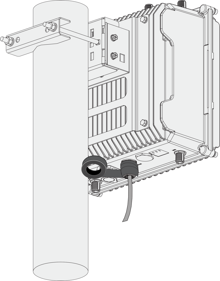 Figure 1: Wrapping with PVC tape
- Cut off about 50 cm waterproof tape. Stretch it to double its length and wrap three layers around the connector with a 50% overlap. Hold the tape in place with your hand for a few seconds.
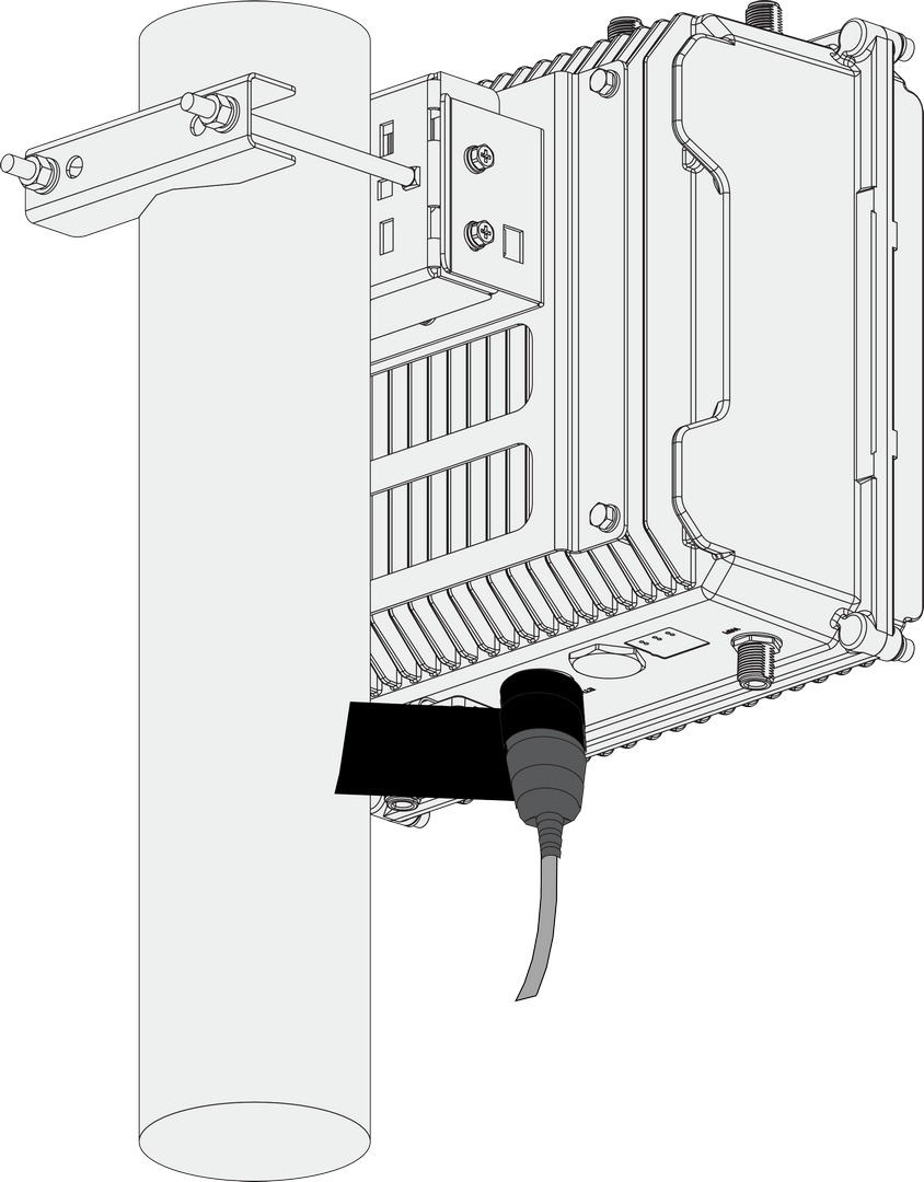 Figure 1: Wrapping with waterproof tape
- Wrap three additional layers with PVC tape with natural uncoiling force and a 50% overlap. Ensure to cover the head and the tail of the connector.
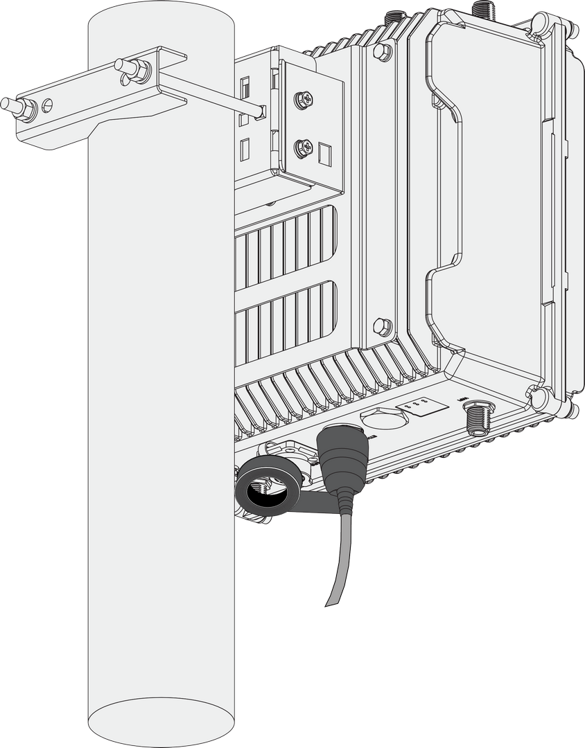 Figure 1: Final PVC wrapping
Power On the Gateway
Do not power the device if any antenna port has been left open.
The gateway supports multiple power supply options. Connect the gateway to the appropriate power source based on your requirements.
PoE (Power over Ethernet)
-
Connect the Ethernet cable—already attached to the gateway’s ETH (PoE) port—to the PoE port of the injector.
-
Plug the injector into a power outlet to power up the gateway.
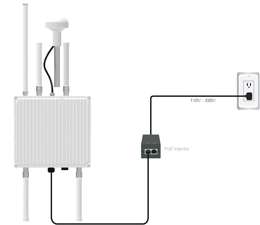 Figure 1: Powering the gateway using PoE
DC Power Input (9–36 V DC)
The gateway supports an external power supply through its DC input port. You can either use the included power cable to connect the gateway to your own 9–36 V DC power source, or power the gateway with the RAK9155 Battery Plus.
RAK9155 Battery Plus is not included in the bundle, it needs to be purchased separately.
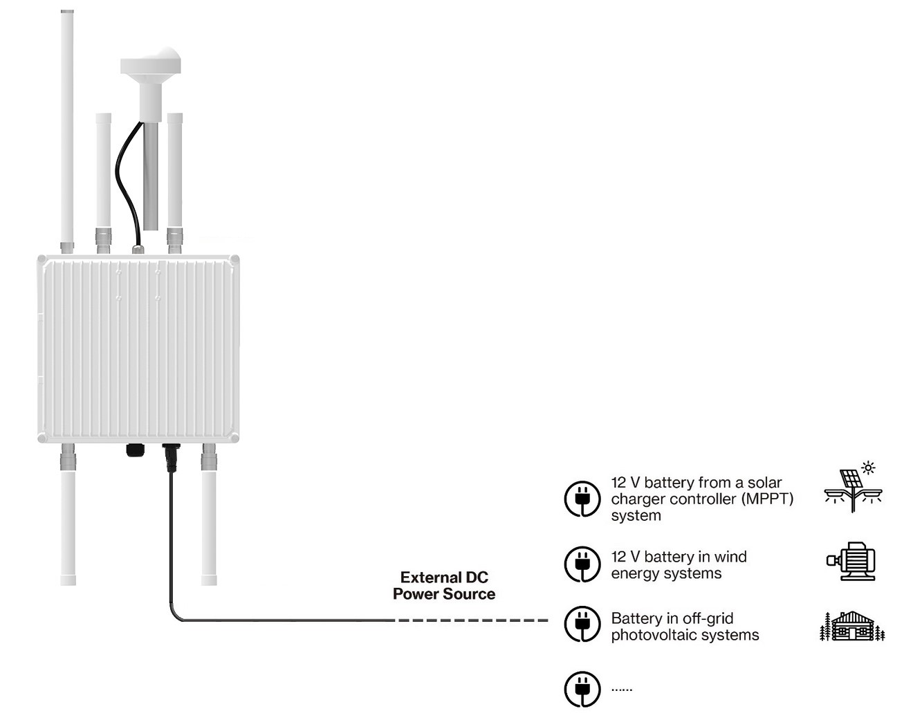 Figure 1: Powering the gateway using external DC power supply