Environmental and Barometric Monitoring Solution Quick Start Guide
Prerequisites
Before proceeding with each step for using the Environmental and Barometric Monitoring Solution, make sure to have all the necessary items listed below:
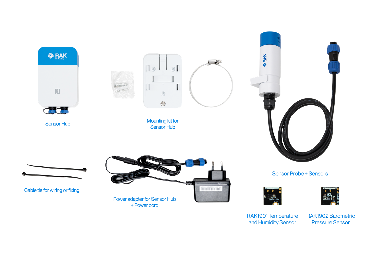 Figure 1: Environmental and Barometric Solution Package Inclusion
Hardware Tools
- Environmental and Barometric Monitoring Solution
- Solar Battery Lite for Sensor Hub (optional)
- Additional accessories: Probe Cable, Probe Splitter, power supply, and others (numbers and variations depending on the use case)
- An Android or iOS mobile device with Bluetooth and NFC
Software
WisToolBoxSolution Configuration
Sensor Hub Setup
SIM Card Installation
If the selected solution uses the NB-IoT/LTE CAT-M wireless communication mode, follow these steps to insert a SIM card. If you opt for the LoRaWAN wireless communication mode, skip this section, as a SIM card is not required.
- Remove the back cover by unscrewing the four screws with a cross screwdriver.
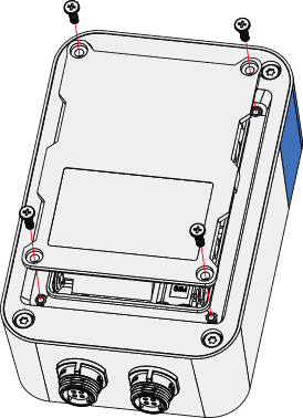 Figure 1: Remove the back cover
- Insert the SIM card into the groove, then gently push it into the card slot.
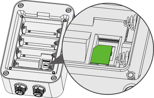 Figure 1: Insert a SIM card
 Sensor Hub Mounting
Wall Mounting
- Use a 5 mm drill bit to drill holes in the wall, then insert the screw anchors into the holes.
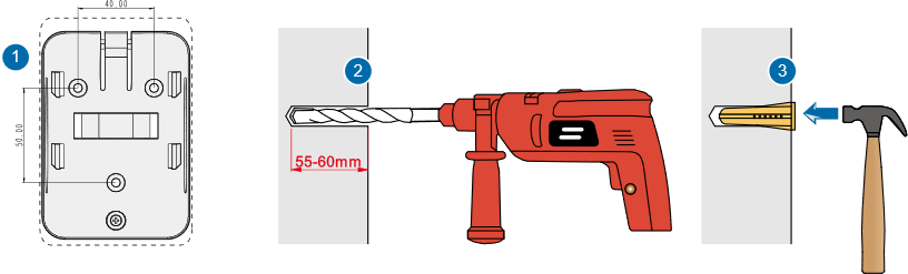 Figure 1: Installation preparation
- Secure the mounting bracket to the wall by using self-tapping screws.
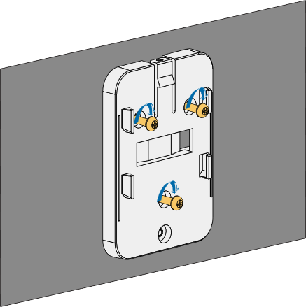 Figure 1: Secure the mounting bracket
- Align the device's hanging tab with the slots on the bracket, and then insert the tab into the slots. Pull the device downwards until it snaps into place.
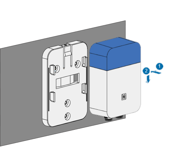 Figure 1: Align the device with the hanging tabs
Pole Mounting
- Secure the mounting bracket to the pole using a steel strap.
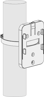 Figure 1: Fix the mounting bracket
Mount the bracket on a pole with a 50-80 mm diameter. For larger poles, use a bigger steel strap. The standard kit does not include a larger steel strap. Purchase separately if needed.
- Align the hanging tab of the device with the slots on the bracket, then insert the tab into the slots. Gently pull the device downwards until it securely snaps in place.
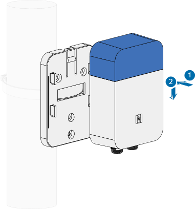 Figure 1: Device installation
- Insert a security screw at the top to fasten the device and the bracket together.
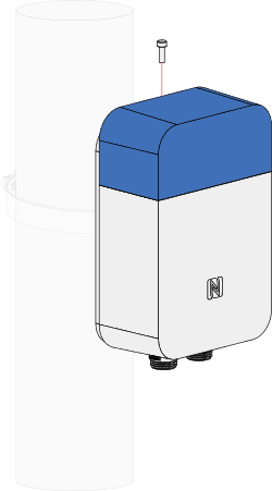 Figure 1: Fasten the device and the bracket
RAK2560 WisNode Sensor Hub + Environmental and Barometric Monitoring Sensor Setup
Sensor Probe + Environmental and Barometric Monitoring Sensor Installation
The RAK1901 temperature and humidity sensor and the RAK1902 barometric pressure monitoring sensor comes pre-assembled with the Sensor Probe by default at the factory, so no additional assembly is required.
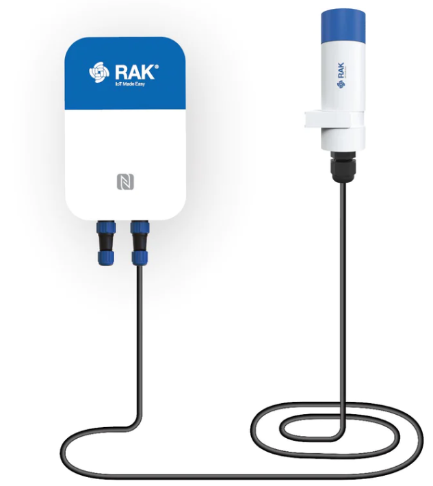 Figure 1: SensorHub and Sensor Probe
Power Supply Setup
RAK9154 Solar Battery Installation
SensorHub supports three power supply methods: battery power, connection to a solar panel or a 12 VDC power supply.
Mount the bracket on a pole with a 50-80 mm diameter. For larger poles, use a bigger steel strap. The standard kit does not include a larger steel strap. Purchase separately if needed.
- Secure the mounting bracket on the pole with two steel straps.
Figure 1: Secure the mounting bracket- Attach the mounting plate to the RAK9154 with two (2) M3 screws.
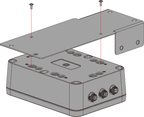 Figure 1: Attach the mounting plate
- Install the RAK9154 to the back of the solar panel with four (4) screws and nuts.
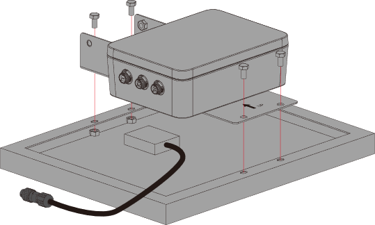 Figure 1: Attach RAK9154 to solar panel
- Connect the cable of the solar panel to the PV input connector of RAK9154. Install two (2) M6 screws to the mounting plate with a clearance of about 3 mm.
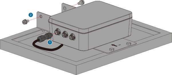 Figure 1: Connector the RAK9154
- Suspend the solar panel on the mounting bracket, adjust its angle and direction, and then tighten the two (2) M6 screws along with the remaining two screws.
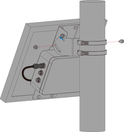 Figure 1: Install the solar panel combination
- Connect Sensor Hub and RAK9154. Use a cable to link the remaining connection port of the Sensor Hub to the lithium battery Output 1 SP11 connection port of RAK9154.
When connecting to RAK9154, ensure that the Sensor Hub is connected to the Output 1 connection port.
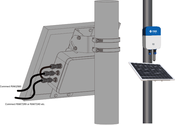 Figure 1: Connect the Sensor Hub and RAK9154
- Once the connection is complete, the Sensor Hub is ready to be powered up.
12 VDC Power Supply Installation
- Connect the power adapter to the external power cable of Sensor Hub using a circular DC connector.
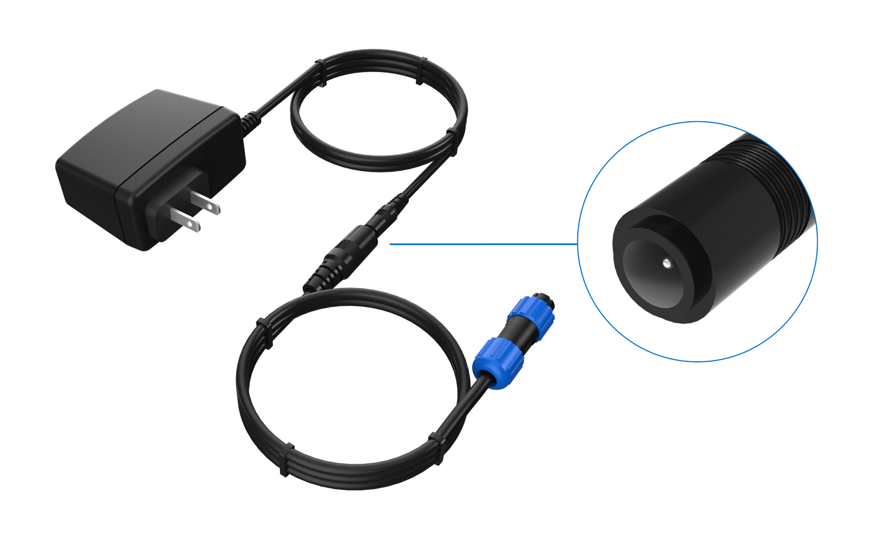 Figure 1: Power Adapter Connection
- Connect the external power cable to the Sensor Hub using the SP11 connector.
- Align the white dot mark on the SP11 connector plug of the external power cable with the white dot mark on the Sensor Hub SP11 connector socket, and push the plug firmly into the socket.
- After the plug and socket are connected, tighten the locking nut to secure the connection of the SP11 connector. The external power cable can connect to any Sensor Hub connection port.
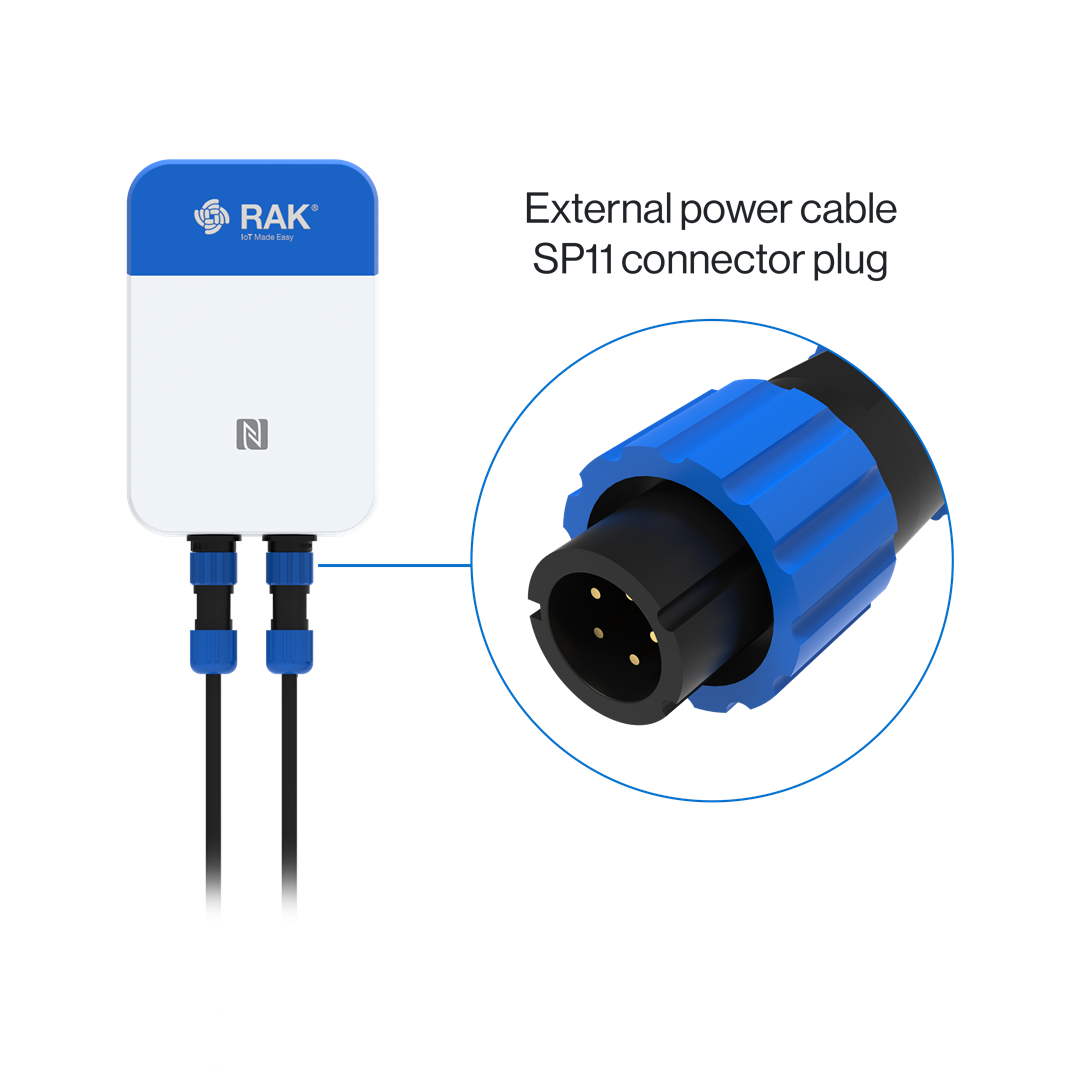 Figure 1: Connect the external power cable
Software Configuration Guide
Sensor Hub Configuration
Power Up Sensor Hub
After installing all hardware components, connect the power supply. If the power supply consists of a solar panel and a battery, the device will power on automatically once all hardware has been installed.
To prevent damage to the device, refrain from powering up the Sensor Hub before connecting it to the sensor. It is advisable to use the 12 VDC adapter provided with the Sensor Hub for optimal performance.
Connect Sensor Hub to WisToolBox
-
Download and install the WisToolBox app on your smart mobile device. The WisToolBox app is available for download from the Apple App Store and the Android Google Play Store.
-
Initiate the app and confirm that NFC and Bluetooth are enabled on your mobile device. Click on START.
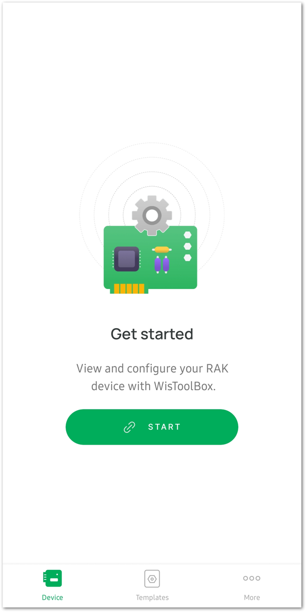 Figure 1: Start App
- On the Select connection mode menu, choose NFC Activation.
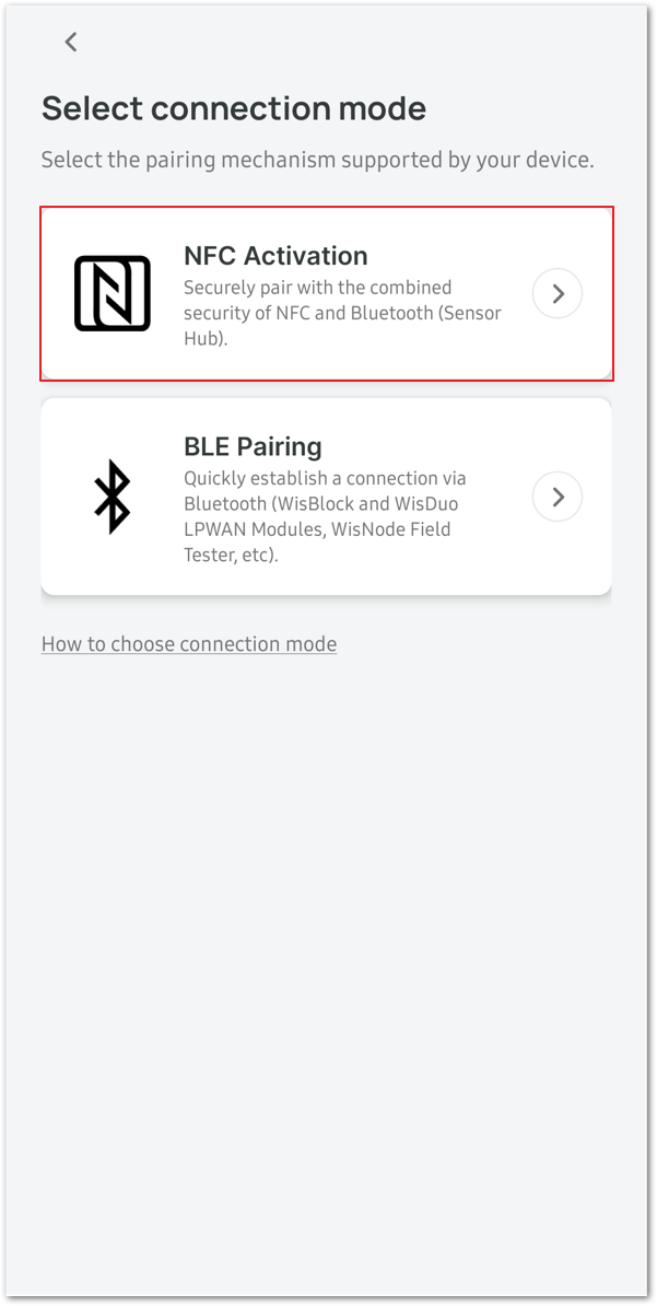 Figure 1: Select NFC Activation
- Select the Sensor HUB option in the device selection interface to establish a connection.
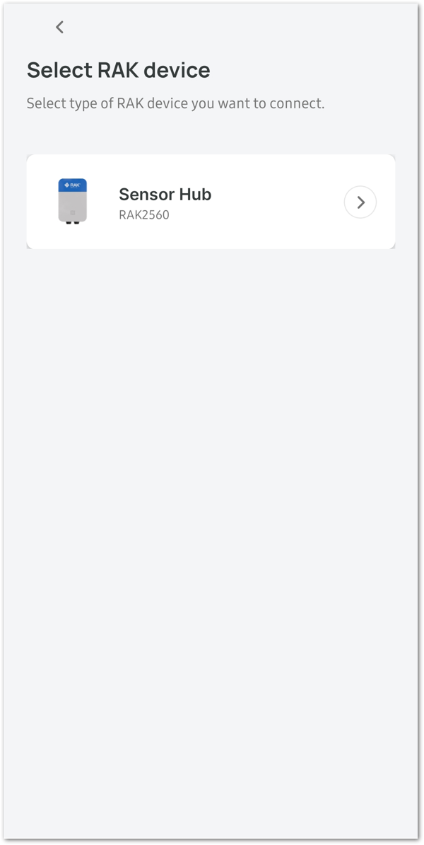 Figure 1: Select Sensor Hub
- Click the CONNECT button to initiate the scanning process for devices.
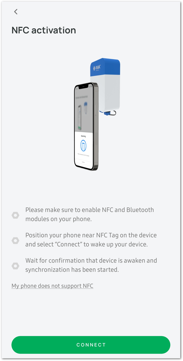 Figure 1: Click on the CONNECT button
- Hold your mobile device close to the N symbol on the Sensor Hub device.
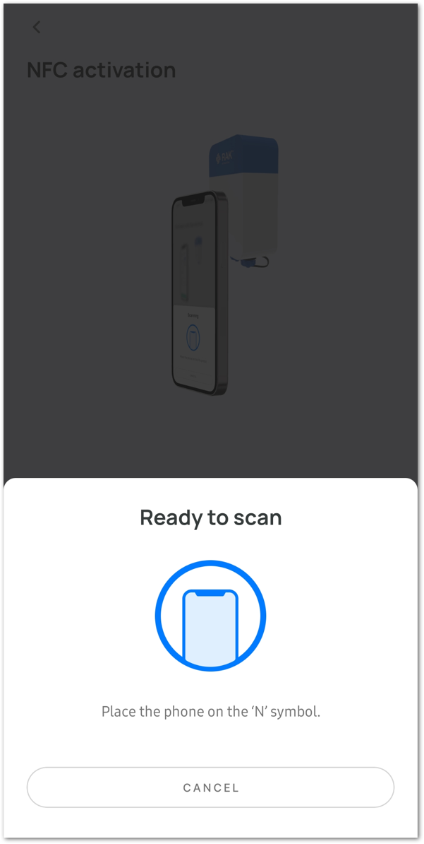 Figure 1: Scanning in progress
The detection of the Sensor Hub device indicates that the device has been successfully powered up.
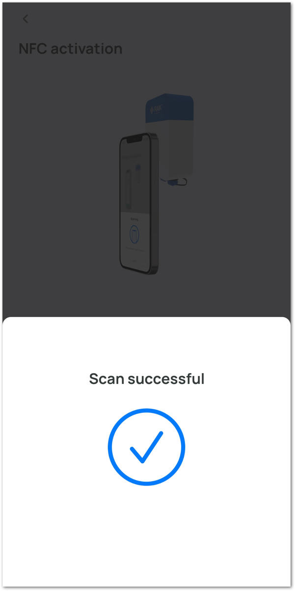 Figure 1: Scan Successful
- After the connection is established, there will be a synchronization of device data. This process may take some time.
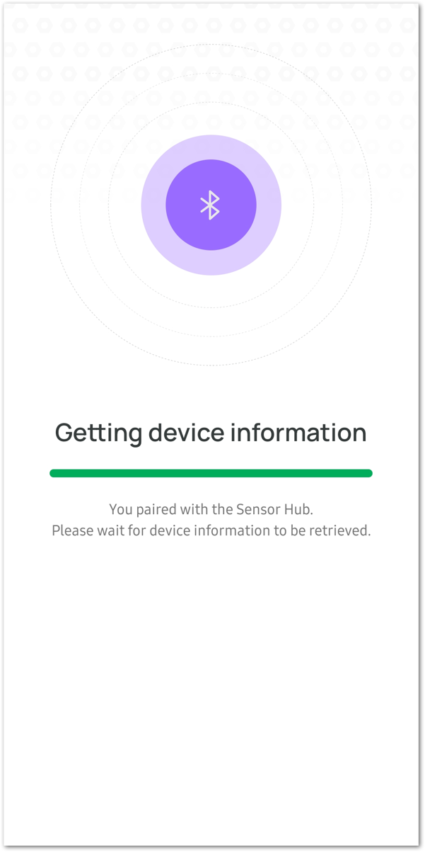 Figure 1: Sync Device
- By default, if no connection is established within 30 seconds, the BLE broadcast of the Sensor Hub will automatically shut down. To establish a connection, connect the RAK device immediately after turning on the power or restart the power.
- Certain Android smartphones may necessitate enabling GPS to connect to BLE. Enabling GPS does not involve the use or sharing of sensitive information with the app.
- Upon completion of data synchronization, the app will automatically transition to the SENSOR HUB INFO page.
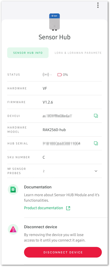 Figure 1: SENSOR HUB INFO page
- While on the SENSOR HUB INFO page, configure the Uplink Settings according to the selected network.
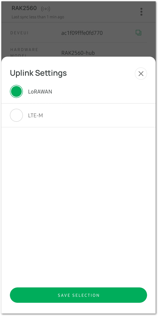 Figure 1: Uplink Settings option
- Once configured, click SAVE SELECTION, and then the APPLY button to implement the configuration options.
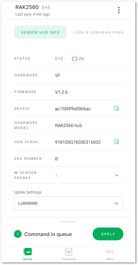 Figure 1: Apply the configuration options
After a few seconds, the synchronization progress will be completed, concluding this process.
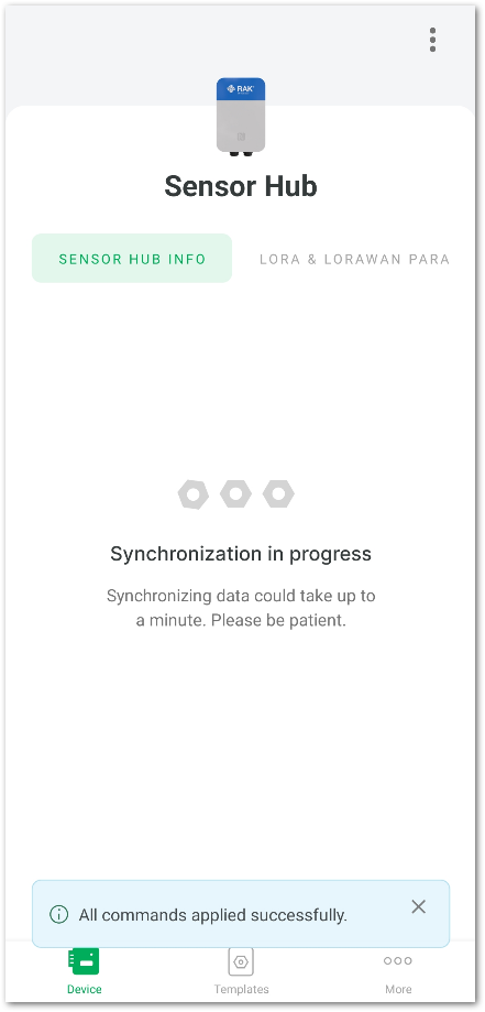 Figure 1: Commands applied successfully
Sensor Hub Network Configuration
LoRaWAN Configuration
This section focuses on configuring the LoRaWAN parameters and joining the network. Before proceeding with the following steps, ensure that the gateway and Sensor Hub are connected to the server.
Refer to the Connect the Gateway to the Server and Connect Sensor Hub to the Server sections for detailed instructions.
- Click the LORA & LORAWAN PARAMETERS tab. Configure the following parameters:
- Global settings
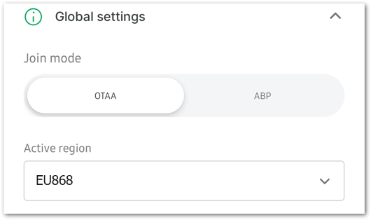 Figure 1: Global Settings
- Join mode: Configure the Join mode based on the device's network access mode: Over-The-Air Activation (OTAA) or Activation By Personalization (ABP). Make sure it matches the join mode registered on the network server.
- Active region: Set the Active region to the device's frequency plan. Ensure that it is consistent with the gateway and device frequency plan registered on the network server.
Supported frequency bands include CN470, RU864, IN865, EU868, US915, AU915, KR920, AS923-1/2/3/4.
LoRaWAN keys, ID, EUI-
For the OTAA join mode, configure the following parameters: Application EUI, Application key, and Device EUI.
 Figure 1: OTAA join mode configuration
- Application EUI: Confirm that it matches the device's Application EUI as registered in the network server.
- Application key: Verify its alignment with the device's Application key registered in the network server. Click GENERATE KEY to create a new key if needed.
- Device EUI: Confirm that it matches the Device EUI registered in the network server.
-
For the ABP join mode, configure the following parameters: Application session key, Device address, and Network session key.
-
Data on LoRa® network
 Figure 1: Data on LoRa® network
- Confirm mode: Message confirmation mode.
- Enable auto join: Determine whether to activate automatic network access. When enabled, the device will join the network automatically upon powering up.
- Network status: Indicates the status of the network connection. It will be activated automatically once successfully connected to the network.
- ADR: The Adaptive Data Rate optimizes data rates in the network. Toggle the button to enable or disable it.
- JOIN NETWORK: After completing the network parameter, click the JOIN NETWORK button to run the join network command.
- After clicking JOIN NETWORK, a Message sent message will appear, indicating that the join network command has been sent.
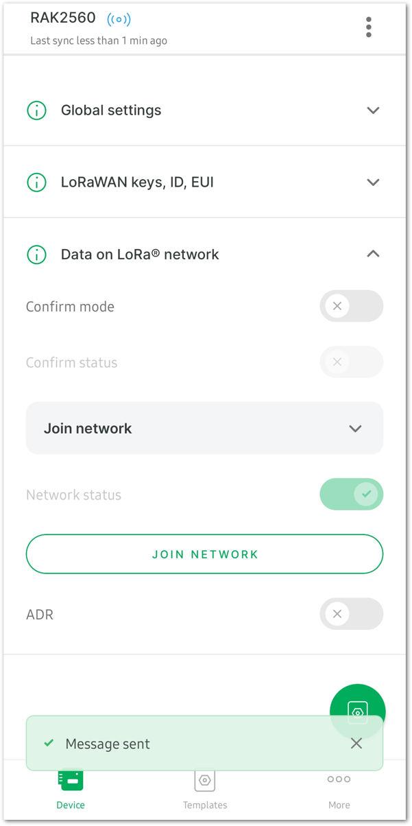 Figure 1: Join the Network
NB-IoT/LTE CAT-M1 Configuration
This section primarily introduces the configuration of LTE-M network parameters. If you are using the NB-IoT/LTE CAT-M1 network, after connecting the device, select LTE-M in the Uplink Settings options on the SENSOR HUB INFO interface to display the LTE-M PARAMETERS configuration tab.
- Click the LTE-M PARAMETERS tab and check the following parameters to ensure that the network is working properly.
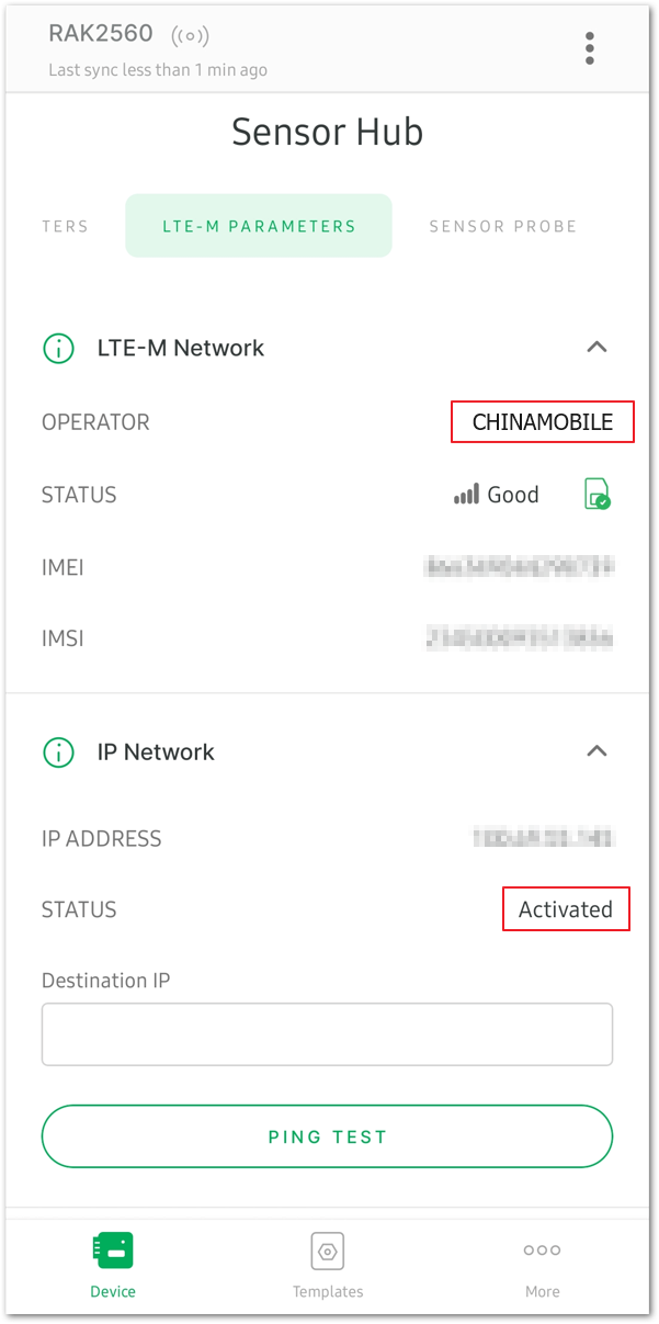 Figure 1: View the LTE-M Parameters tab
- OPERATOR: Shows the Network operator. If the operator's name is displayed, it indicates that the device has recognized the SIM card. For example, CHINAMOBILE.
- STATUS: If the status is Activated, it signifies that the network of the SIM card is functioning normally.
- Select the Application option to configure the cellular network parameters.
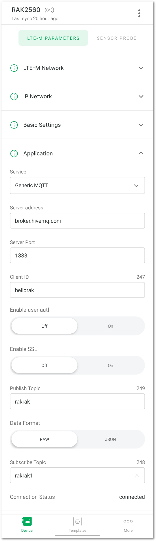 Figure 1: Configure the cellular network parameters
- Service: Choose a service, either AWS IoT Core or Generic MQTT. For this guide, use Generic MQTT as an example.
- Server address: Input the server address. Using the external MQTT broker as an example, enter
broker.hivemq.com. Enter the address based on your specific use case. - Server Port: Specify the server port according to your configuration.
- Client ID: Set the client ID for your device.
- Enable user auth: Decide whether to activate user authentication for your device.
- Enable SSL: Decide whether to activate SSL (Secure Sockets Layer) for secure communication.
- Publish Topic: Specify the topic for publishing messages.
- Data Format: Select JSON as the preferred format for data transmission.
- Subscribe Topic: Subscribe to the topic for receiving incoming messages, as illustrated in this example.
- Following the configuration, click APPLY in the command list at the bottom of the interface to implement the changes. If the message All commands applied successfully appears, it indicates a successful configuration modification.
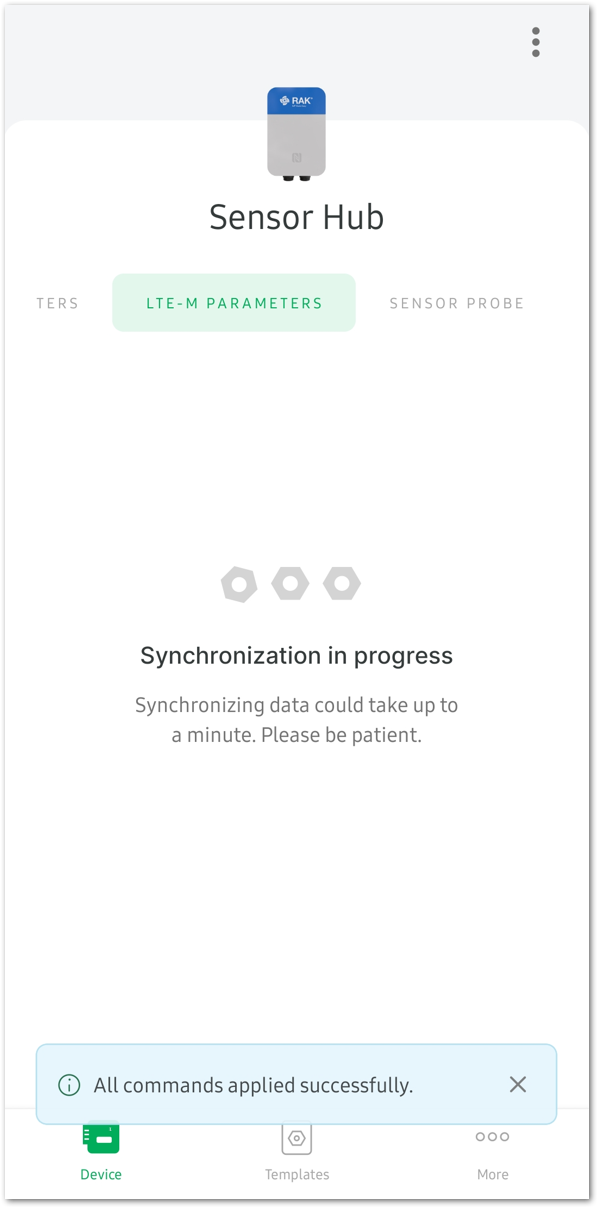 Figure 1: Apply the modified configuration
- When configured correctly and successfully connected to the server, the Connection Status will display as connected.
 Figure 1: Successfully connected to the server
Sensor Configuration
This section details the configuration process of the RAK1901 temperature and humidity sensor and RAK1902 barometric pressure sensor. You can view monitoring data and device details of the environmental and barometric sensors. At the same time, you can configure the uplink sending period, threshold and other information of each monitoring parameter.
- To start with, click the SENSOR PROBE tab to display the connected sensor.
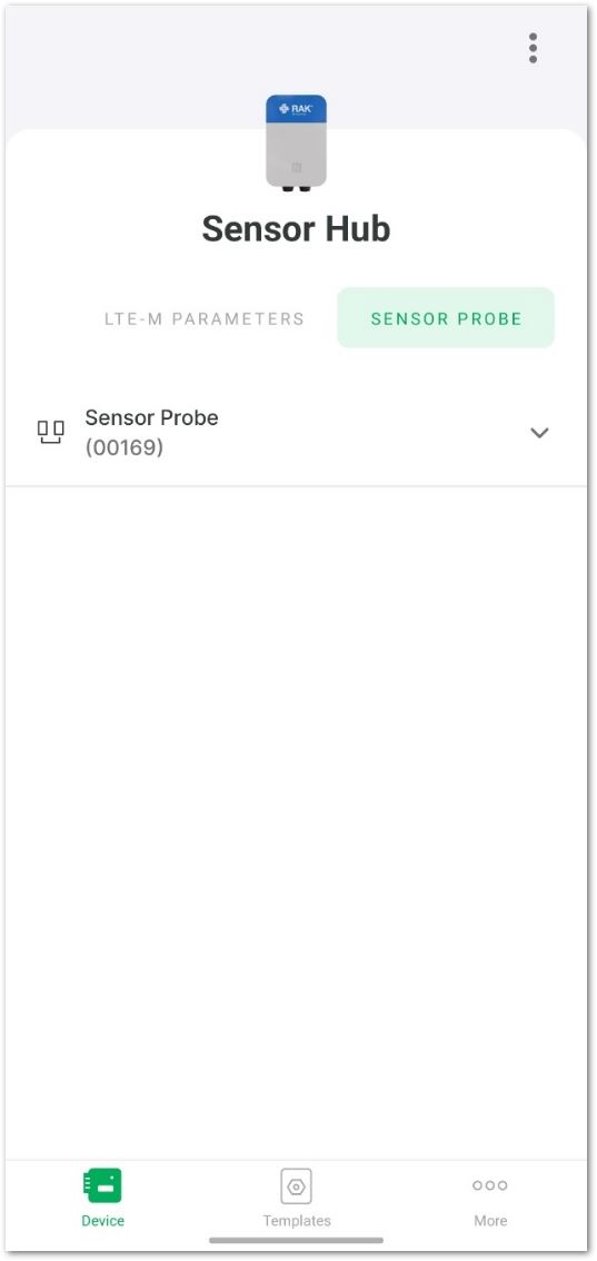 Figure 1: Environmental and Barometric sensor
- Click the down arrow to expand the details of the temperature and humidity sensor (RAK1901) and the barometric sensor (RAK1902).
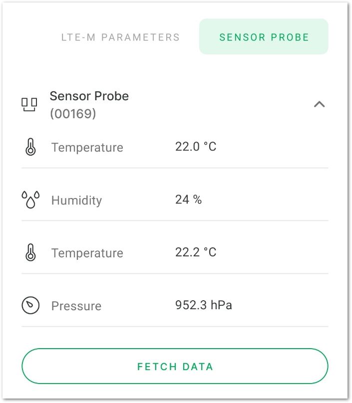 Figure 1: Sensor details
- (RAK1901) Temperature
- (RAK1901) Humidity
- (RAK1902) Temperature
- (RAK1902) Pressure: Barometric pressure value
- FETCH DATA: Update the monitoring data from the sensor.
- Device details
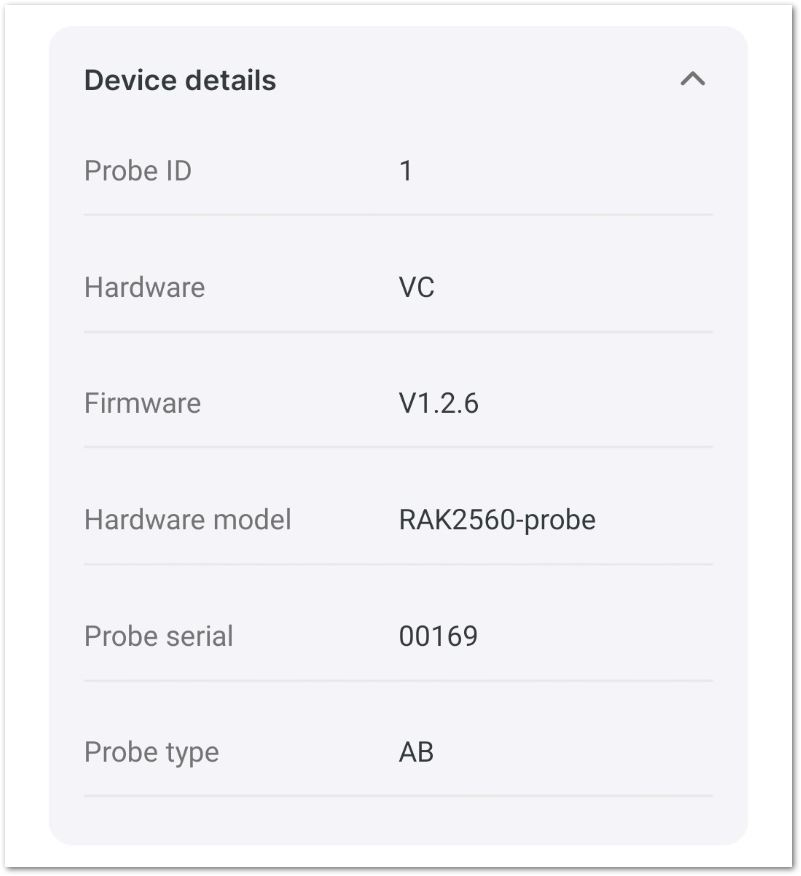 Figure 1: Sensor details
For this example, fetch the data of the Wind speed and set the parameters by then choosing the Wind speed feature.
- Configure the periodic uplink data sending, thresholds, and other relevant information for the sensor.
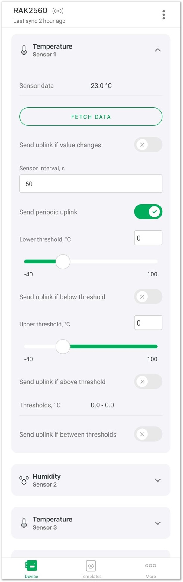 Figure 1: Set the sensor parameters
- Sensor data: Information provided by the sensor.
- FETCH DATA: Retrieve the latest sensor data.
- Send uplink if value changes: If the sensor data changes, send uplink data.
- Sensor interval(s): The payload sending interval in seconds. It determines how often the sensor sends uplink data to the server, with a range interval from 60~86,400 seconds.
- Send periodic uplink: Send uplink periodically according to the sensor interval.
- Lower threshold, ° C: Specifies the minimum acceptable temperature value.
- Send uplink if below threshold: Send uplink data if the value is below the lower threshold.
- Upper threshold, ° C: Specifies the maximum acceptable temperature value.
- Send uplink if above threshold: Send uplink data if the value is higher than the upper threshold.
- Threshold, ° C: Range of acceptable values.
- Send uplink if between threshold: Send uplink data if the value is within the threshold range.
-
Click the downward arrow in the Humidity (Sensor 2), Temperature (Sensor 3), and Pressure (Sensor 4) tab bar to set the periodic uplink sending and thresholds of the remaining parameters.
-
After completing the modifications, a message Commands in queue will appear at the bottom of the interface. Click APPLY to send the parameter update commands.
-
When the message All commands applied successfully. appears on the interface, it indicates that the parameter update commands have been successfully sent.
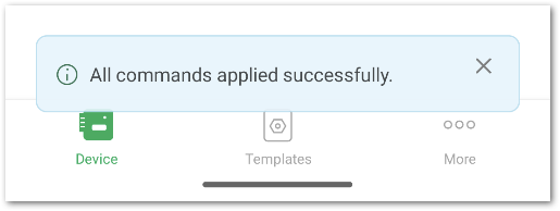 Figure 1: Apply commands
- REMOVE SENSOR PROBE: Detach the sensor.
- RESTORE TO DEFAULT SETTINGS: Reset the Sensor Probe to its default settings.
- UPGRADE SENSOR PROBE: Upgrade the firmware of the Sensor Probe.