RAK2461 WisNode Bridge IO Lite Quick Start Guide
The RAK2461 WisNode Bridge IO Lite is an industrial-grade LoRaWAN® bridge device that connects digital inputs, digital outputs, and RS-485 industrial equipment to a LoRaWAN network. This guide covers hardware setup, interface configuration, and LoRaWAN network preparation before field deployment.
Hardware Preparation
Package Contents
Variant for Wall Mounting
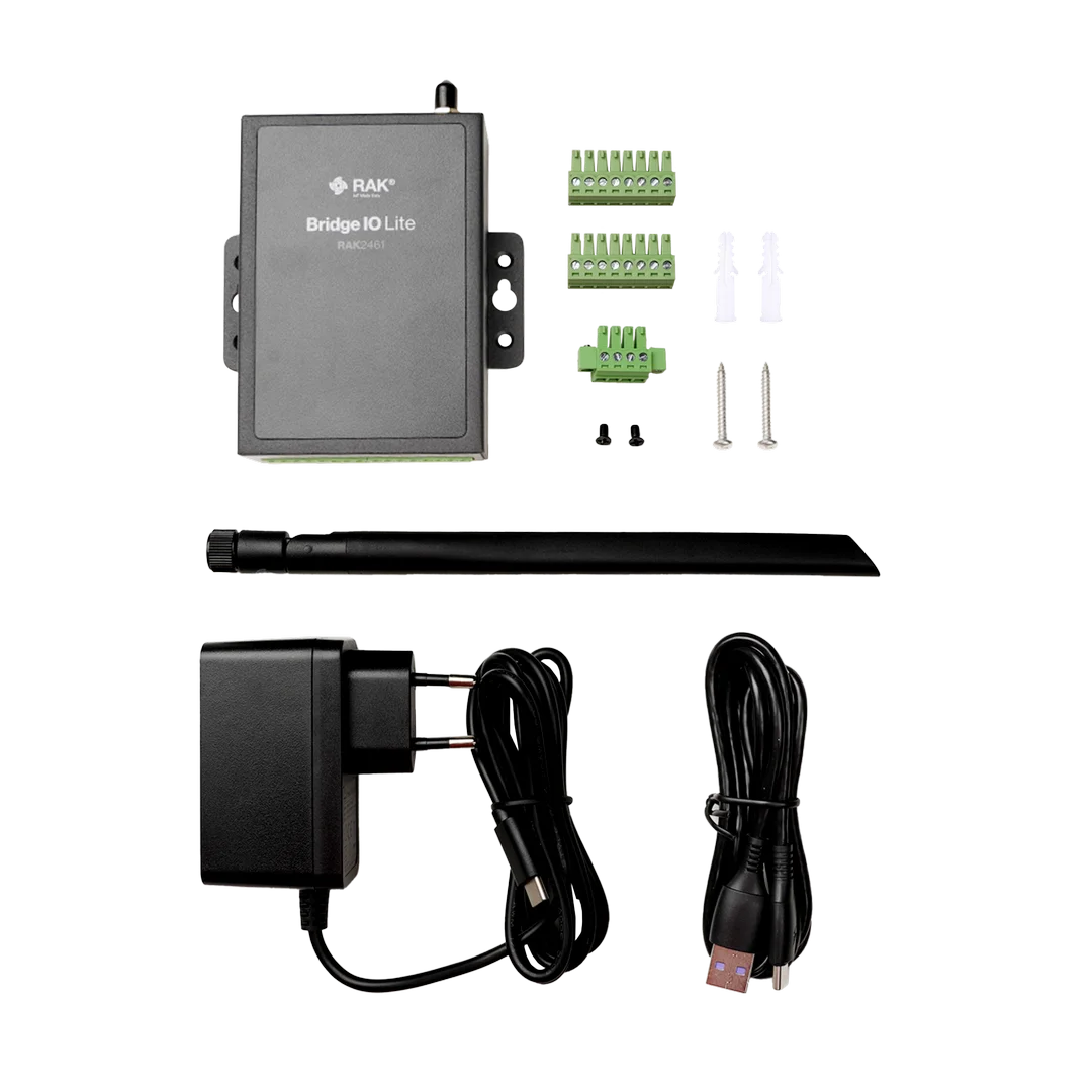 Figure 1: RAK2461 Package Inclusions (Wall Mount)
- One (1) RAK2461 WisNode Bridge IO Lite (RS485-DIx4-DOx1 or RS485-DOx4)
- One (1) Screw Kit
- One (1) LoRa Antenna
- One (1) Power Adapter
- One (1) USB Cable (Type C to Type A)
- One (1) 4-Pin Terminal Block
- Two (2) 8-Pin Terminal Block
Variant for DIN Rail Mounting
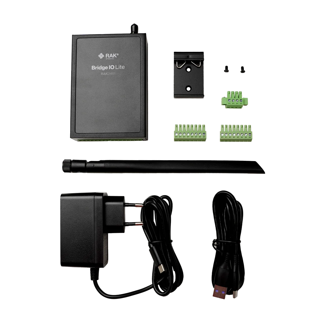 Figure 1: RAK2461 Package Inclusions (DIN Rail)
- One (1) RAK2461 WisNode Bridge IO Lite (RS485-DIx4-DOx1 or RS485-DOx4)
- One (1) DIN rail Mounting Kit
- One (1) LoRa Antenna
- One (1) Power Adapter
- One (1) USB Cable (Type C to Type A)
- One (1) 4-Pin Terminal Block
- Two (2) 8-Pin Terminal Block
Additional Requirements
Depending on your RAK2461 variant and application, prepare the external device that you plan to connect, such as:
- RS-485 devices
- Digital Input (DI) devices
- Digital Output (DO / Relay) devices
Hardware Assembly
Attach LoRa Antenna
Attach the provided LoRa antenna to the antenna connector on the RAK2461.
Always install the LoRa antenna before powering on the device. Operating the device without an antenna may degrade RF performance or cause damage to the RF front end.
Connect External Devices to the RAK2461
Refer to the corresponding guide below to connect the required RS-485, Digital Input, or Digital Output device to the RAK2461.
- Connect RS485 Device to the RAK2461
- Connect DI Device to the RAK2461
- Connect DO Device to the RAK2461
These interfaces allow the Bridge IO to collect field data and control external devices through LoRaWAN.
Power On the RAK2461
The RAK2461 device can be powered either by:
- 9–24 VDC input
- USB Type-C
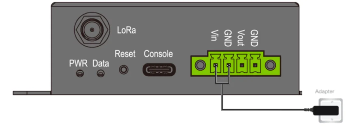 Figure 1: Power interface connection
- The USB Type-C port is intended for configuration and powering the device only.
- When powered via USB Type-C, the Vout port does NOT supply power to connected sensors.
- To power both the RAK2461 and connected sensors, use the 9–24 VDC input.
Network Setup Before Deployment
Before deploying the device in the field, configure the interfaces and LoRaWAN parameters locally to ensure correct operation and reduce the risk of network or configuration issues on site.
Prerequisites
- A LoRaWAN gateway within range
- A Windows or macOS computer
- Download and install the IO.Box Desktop application:
After installation, launch the application to proceed.
Connect Bridge IO Device to IO.Box
To configure the Bridge IO device, connect it to a PC using a USB Type-C configuration cable and access it through the IO.Box application. Follow the steps below:
-
Connect the RAK2461 to your computer using a USB Type-C cable.
NOTE- USB Type-C can be used to power the RAK2461 during local configuration. However, the Vout port does not provide power when the RAK2461 is powered through USB Type-C. If the connected external device requires power from the RAK2461 Vout port, connect the 9–24 VDC power supply.
- Make sure the USB Type-C cable supports data transfer and that no other serial application is using the RAK2461 COM port.
-
In the IO.Box console, click Connect Device.
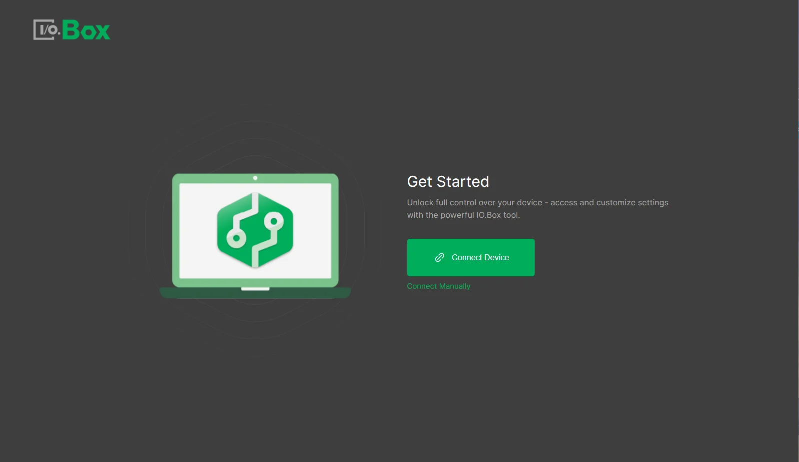 Figure 1: IOBox get started
If the message No device detected appears, check the following:
- Double-check the quality of the USB cable and if the correct COM port is used.
- Check if other terminal software is active and still connected to the RAK2461.
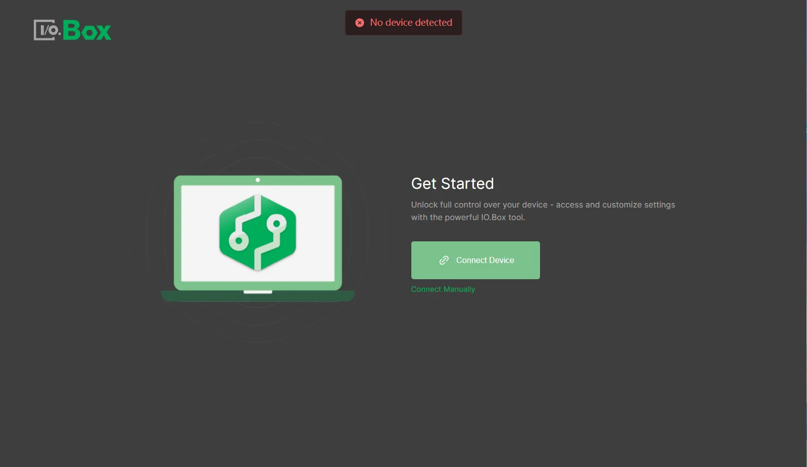 Figure 1: No device error
- On the IO.Box dashboard, all connected devices are displayed in a list showing their model numbers and EUIs. Click Connect next to the target device to begin configuration.
Interface Configuration
After connecting the RAK2461 to IO.Box, configure the interface required for your device variant and application. Refer to the corresponding guide:
- RS485 Interface Configuration
- Digital Input Interface Configuration
- Digital Output Interface Configuration
Configure LoRaWAN Parameters
After configuring the device interfaces, select LoRaWAN from the left menu in IO.Box to configure the LoRaWAN parameters. Once completed, the device can join the LoRaWAN network and transmit data.
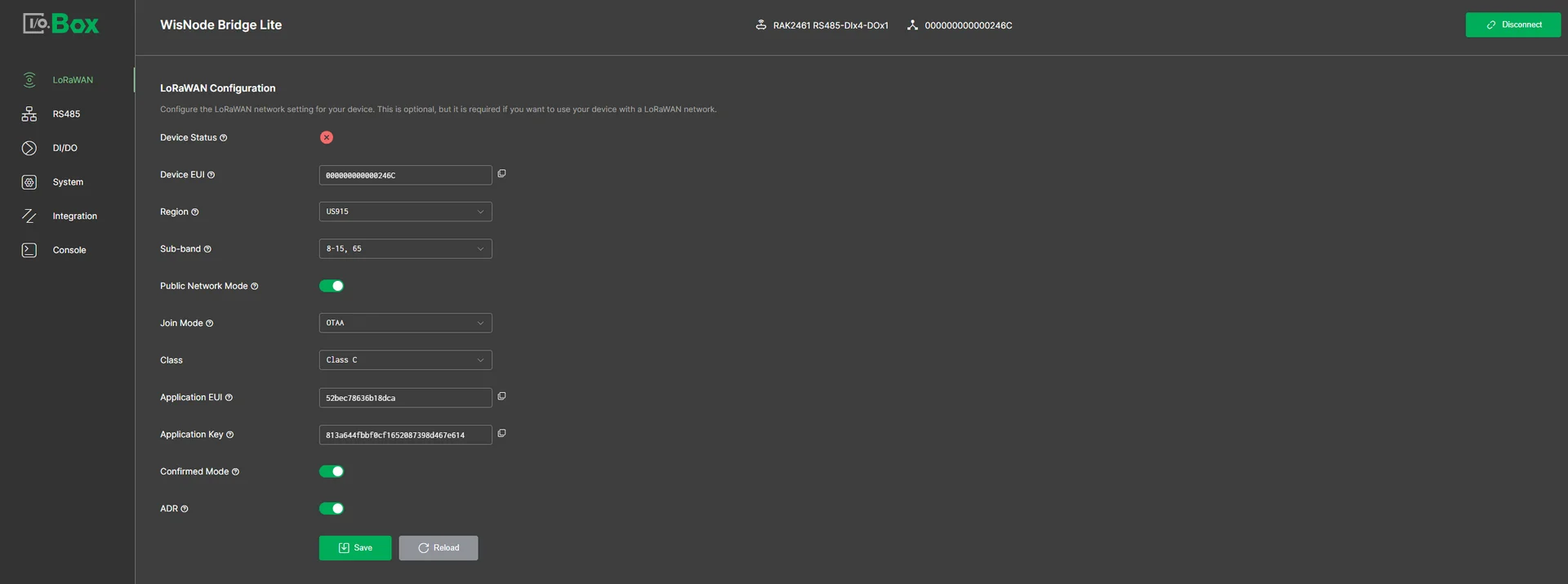 Figure 1: LoRaWAN Configuration Tab
- Device Status: Indicates the device’s connection status to the LoRaWAN network.
- Red: The device is not connected to the LoRaWAN network.
- Green: The device has successfully joined the LoRaWAN network.
- Device EUI: The unique identifier of the device.
- Region: Specifies the LoRaWAN frequency band used by the device. In this document, US915 is selected.
- Sub-band: Select the specific frequency sub-band based on the region's frequency plan.
- Public Network Mode: Determines whether standard LoRaWAN public network parameters are used. Enabled in this document.
- Join Mode: Defines how the device joins the LoRaWAN network. OTAA (Over-The-Air Activation) is selected.
- Class: The type of LoRaWAN communication used by the device. Select Class C.
- Application EUI: The application identifier for the device. Ensure it matches the Application EUI configured in the LoRa network server.
- Application Key: The security key for device-server encryption and authentication. Ensure it matches the Application key in the LoRa network server.
- Confirmed Mode: Message acknowledgment mode. Enabled in this document.
- ADR: Enable Adaptive Data Rate allowing the network server to control the data rate for your device. Enabled in this document.
Connect Bridge IO to LoRa Network Server
After configuring the device interface and LoRaWAN parameters, register the RAK2461 with your LoRaWAN Network Server (LNS). Make sure that the region, activation mode, and corresponding device credentials match the settings configured on the RAK2461.
After the device joins the network, verify that data from the connected interface is received by the LNS.
For interface-specific configuration and uplink verification, refer to the corresponding guide:
- RS-485: Connect Bridge IO to LoRa Network Server for Uplink
- Digital Input: Connect Bridge IO to LoRa Network Server for Uplink
- Digital Output: Connect Bridge IO to LoRa Network Server for Uplink
Installation and Deployment
RAK2461 allows for two installation methods: wall mounting and DIN rail installation.
Wall Mounting
- Drill the wall corresponding to the device dimensions and insert the anchors in the holes.
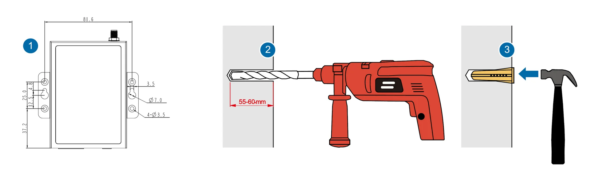 Figure 1: Hole drilling
- Fix the device to the wall with two tapping screws.
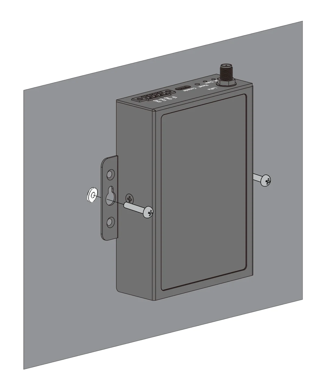 Figure 1: Wall mounting
DIN Rail Mounting
- Attach the DIN rail mounting clip on the device with two M3*6 countersink screws.
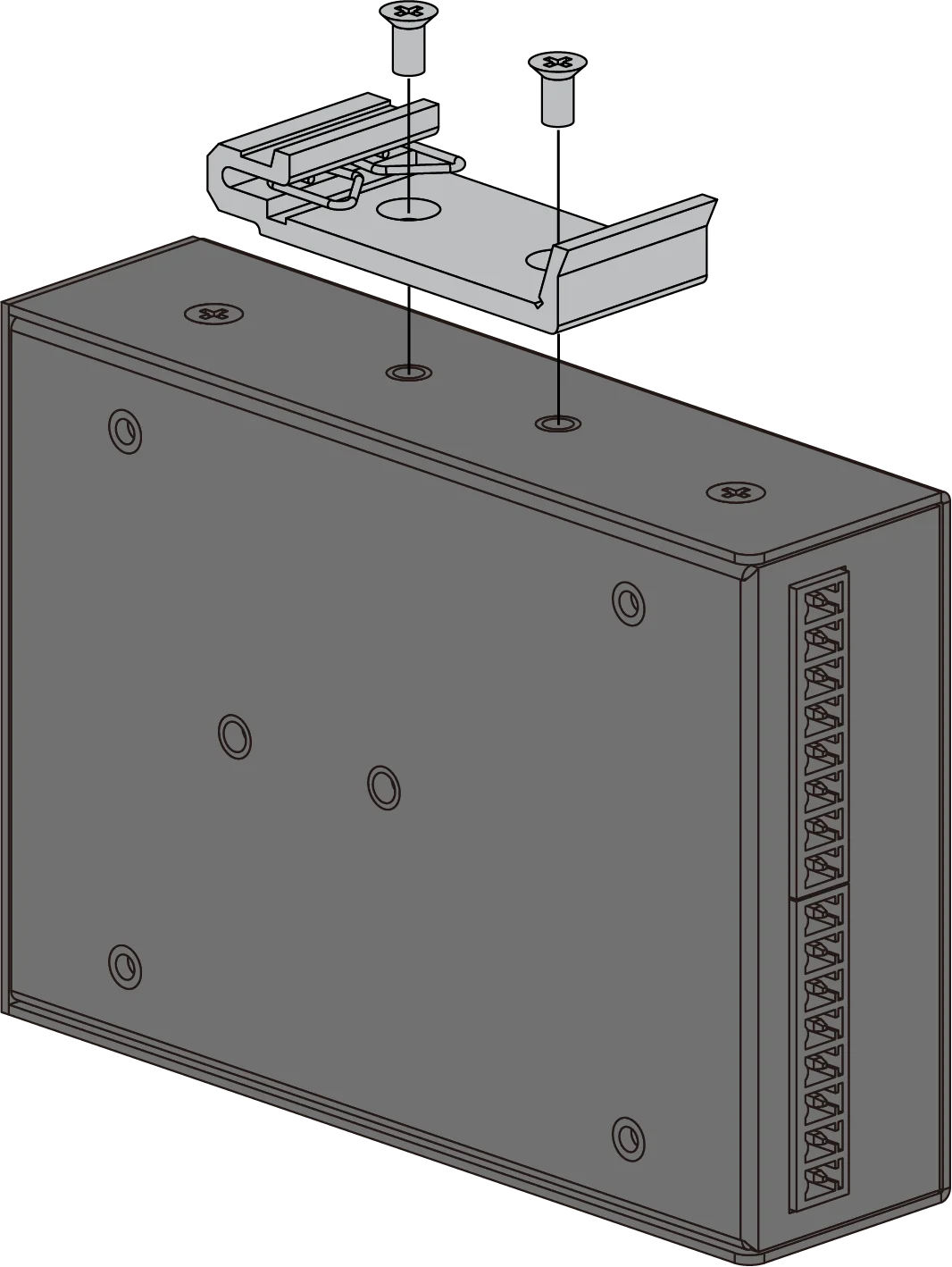 Figure 1: Attaching the clip
- Mount the device to the DIN rail.
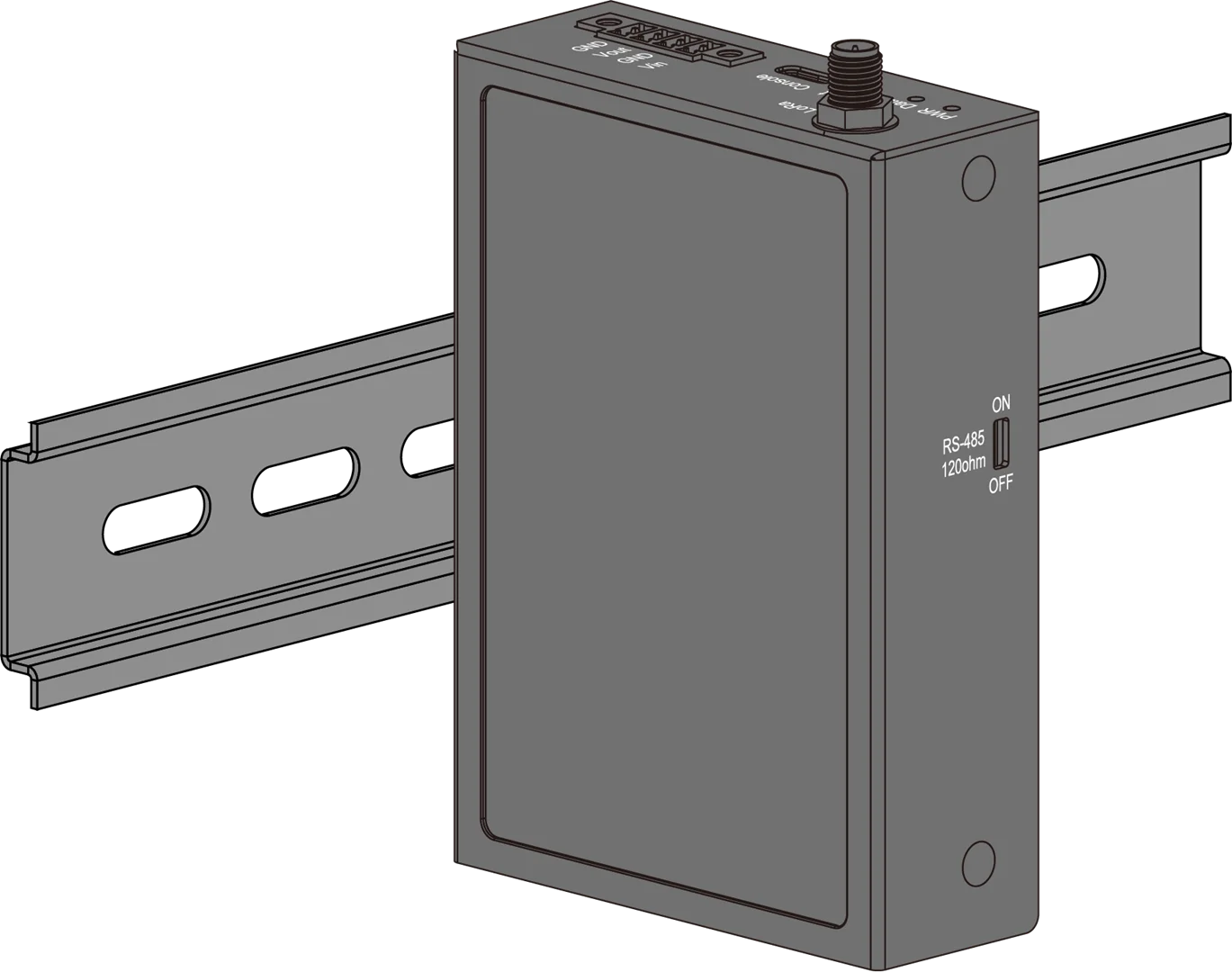 Figure 1: DIN rail mounting
After installation, power on the device and verify that the expected uplink data is received by the LoRaWAN Network Server. If your application uses downlink control, verify the corresponding downlink operation as well.
Once communication is confirmed, the device is ready for normal field operation.
Next Steps
After completing the basic device setup, refer to the following guides based on your application:
- Instant Configuration Uplink – Understand the configuration information automatically reported after LoRaWAN network activation.
- Remote Configuration via LoRaWAN Downlink – Read or modify supported device parameters remotely through LoRaWAN downlinks.


