RAK2560 WisNode Sensor Hub Installation Guide
During installation, make sure that the installer complies with all the necessary safety regulations to ensure personal safety.
Do not place the device and mounting kit on pedestrian walkways to avoid accidental damage to the device or harm to bystanders.
Inserting the SIM Card and Batteries
- Remove the back cover by unscrewing the four screws using a Philips screwdriver.
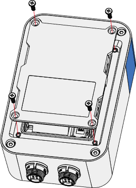 Figure 1: Removing the back cover
- Put the SIM card in the groove and push it into the socket.
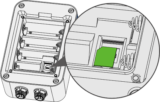 Figure 1: Inserting the SIM card
- Insert the batteries by pressing the negative spring with the battery and fit the positive end in its place.
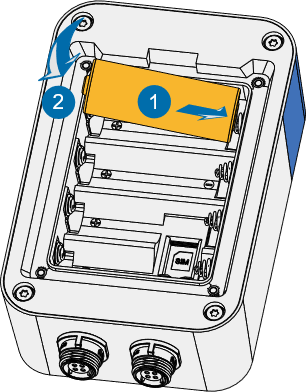 Figure 1: Fitting the batteries
The battery should be 18505 in size.
- Put the back cover back and screw it in place.
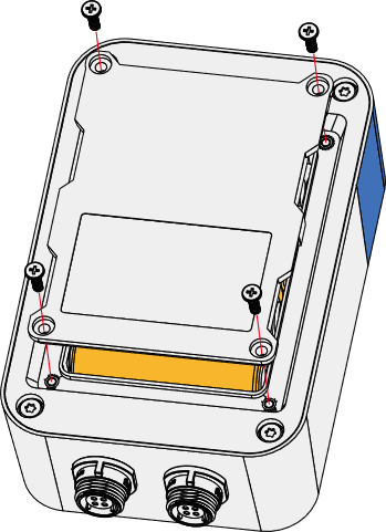 Figure 1: Closing the back cover
- Make sure to properly fit the rubber seal in place to ensure waterproof sealing.
- Screw in the back cover with enough force to seal it but not enough to break it.
Mounting of the Sensor Hub
Wall Mounting
- Using a 5 mm drill head, drill holes in the wall and plug the screw anchors in the holes.
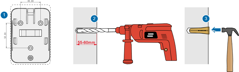 Figure 1: Drilling the wall
- Using the tapping screws, attach the mounting bracket to the wall.
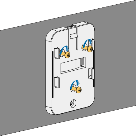 Figure 1: Install the bracket on the wall
Pole Mounting
- Fix the mounting bracket on the pole with one steel strip.
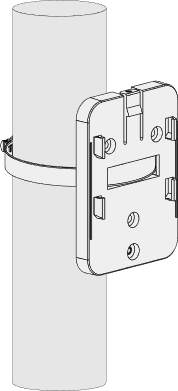 Figure 1: Install the bracket on a pole
The diameter of the pole that is supported by the brackets is 50-80 mm. If the pole diameter is more than this value, larger steel strips can be used. The standard mounting kit does not include larger steel strips. If needed, you should purchase them separately.
- Align the hanging tab of the device with the slot on the bracket, and put the tab into the slot. Then, pull the device down until it clicks in place.
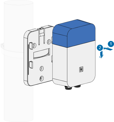 Figure 1: Placing the Hub on the bracket
- Add the security screw on top so the device and bracket are locked together.
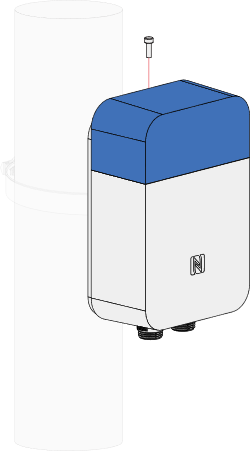 Figure 1: Adding a security screw
Mounting of the Sensor Probe
Wall mounting
- Using a 5 mm drill head, drill holes in the wall and plug the screw anchors in the holes.
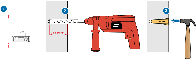 Figure 1: Drilling the wall
- Use two tapping screws to attach the mounting bracket to the wall.
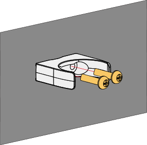 Figure 1: Installing the bracket to the wall
- Clip the probe into the bracket.
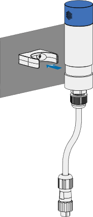 Figure 1: Clipping the probe to the bracket
Pole mounting
Fix the probe on the pole with a steel strip directly.
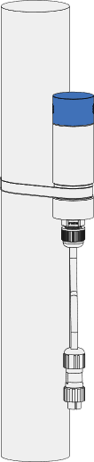 Figure 1: Pole mounting
Connecting Probes to the Sensor Hub
Connecting the Sensor Probe
You have multiple options, depending on the deployment requirements and available space.
- Connect the Sensor Probe to the Hub directly by plugging the cable into one of the free ports on the main body.
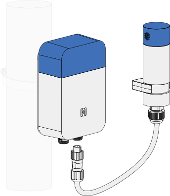 Figure 1: Direct connection
- Connect the probe to the Hub via an extender cable for better placement of the Probe.
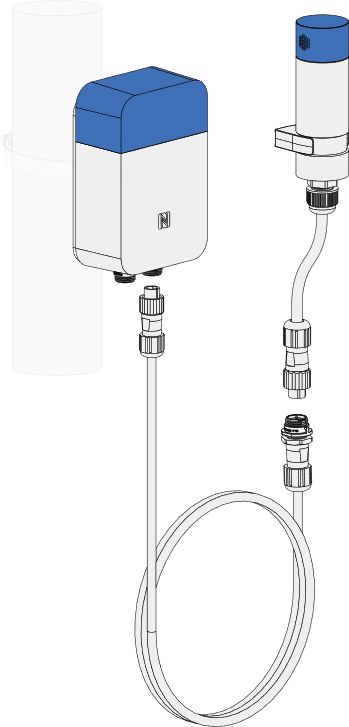 Figure 1: Connection via an extender
- Connect the Probe to the Hub via a splitter cable for the option to connect multiple Probes to the same port of the Hub.
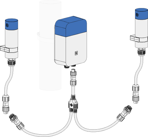 Figure 1: Connection via a splitter
A single port can support a maximum of four (4) Probe IOs or Sensor Probes.
- Connect the Probe to the Hub using a splitter and extender cable at once for maximum placement freedom.
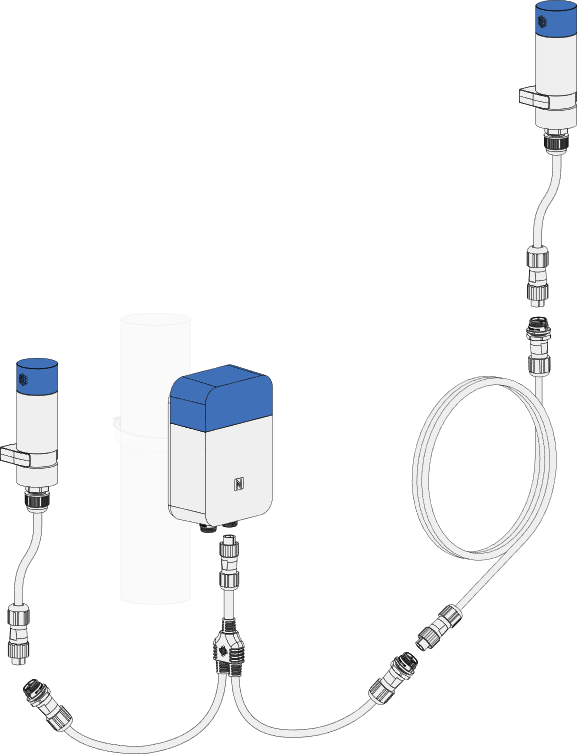 Figure 1: Connection via splitter and extender
Connecting the Probe IO
RAK2560 Sensor Hub can support third-party sensors through the Probe IO.
- Remove the lid using a Philips screwdriver.
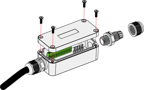 Figure 1: Removing the lid
- Pass the cable of the sensor through the cable gland and the opening of the Probe IO, and connect the cable to the wiring terminal.
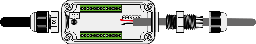 Figure 1: Connecting the cable
The connection of the wiring terminal depends on the type of sensor it is connected to. Different sensors have different pin connection requirements.
- Screw the cable gland body and lock the nut in the proper sequence.
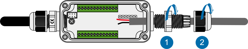 Figure 1: Screw the cable gland
- Put the back cover back and screw it in place.
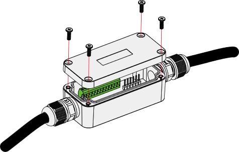 Figure 1: Closing the Probe IO
- Connect the Probe IO to the Hub the same way you would connect a Sensor Probe.
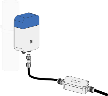 Figure 1: Connection the Probe IO to the Hub