RAK7200 Quick Start Guide
Prerequisites
What Do You Need?
Before going through each and every step in the installation guide of the RAK7200 WisNode Track Lite, make sure to prepare the necessary items listed below:
Hardware Tools
- RAK7200 WisNode Track Lite
- Micro USB Cable
- Gateway in Range, for Testing
- Windows PC
Software Tools
List of Acronyms
| Acronyms | Definition |
|---|---|
| BLE | Bluetooth Low Energy |
| DFU | Device Firmware Upgrade |
| LoRa | Long Range |
| EUI | Electronic Unique Identifier |
| TTN | The Things Network |
What's Included in the Package
- RAK7200 WisNode Track Lite
- Rubberized enclosure
- Micro USB cable
Product Configuration
Interfacing with RAK7200
To interface with the RAK7200 WisNode Track Lite with your Windows Machine, you need to have a serial too. Any serial tool will work, but it is recommended to use the RAK Serial Port Tool.
Connecting to the RAK7200
Once done, follow the listed steps to interface your RAK7200 with your computer.
- Connect the RAK7200 to the USB port of a general-purpose computer using a standard Micro - USB Cable.
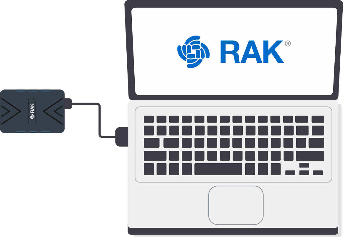 Figure 1: RAK7200 Module Connection
If this is your first time to connect your RAK7200 WisNode Track Lite to your computer, it should automatically download the CH340 driver in order for them to communicate properly. Make sure to have an internet access if you want such automatic installation to be successful. If such process fails, re-plug your Micro - USB cord and proceed to the next step.
-
Go to your Device Manager by pressing: Windows + R and type
devmgmt.msc. Then, look for Other Devices. You can also use the following options:- Search in Start Menu
- Right click My Computer or This PC and click Manage.
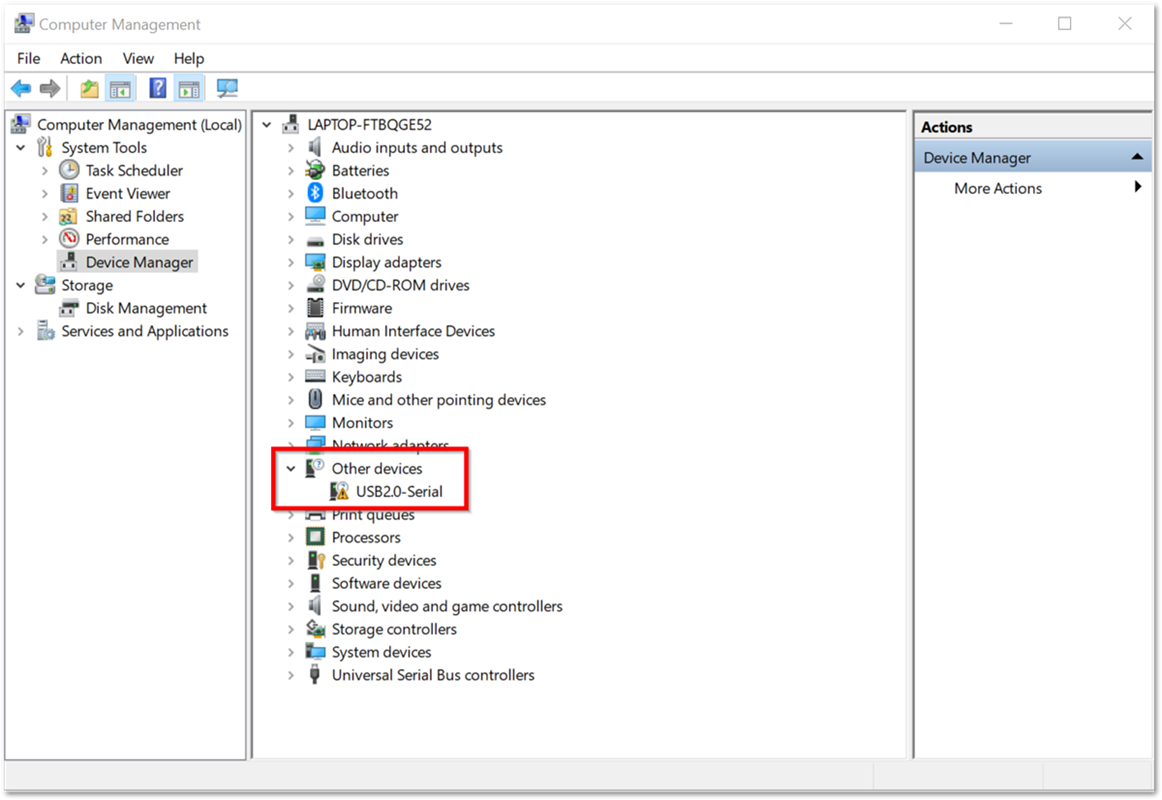 Figure 1: Missing Driver for the RAK811 LPWAN Evaluation Board
- Under Other devices drop down list, right click the unknown USB2.0-Serial driver and choose Search automatically for updated driver software. Again, before doing so, make sure to have an internet access or it will fail.
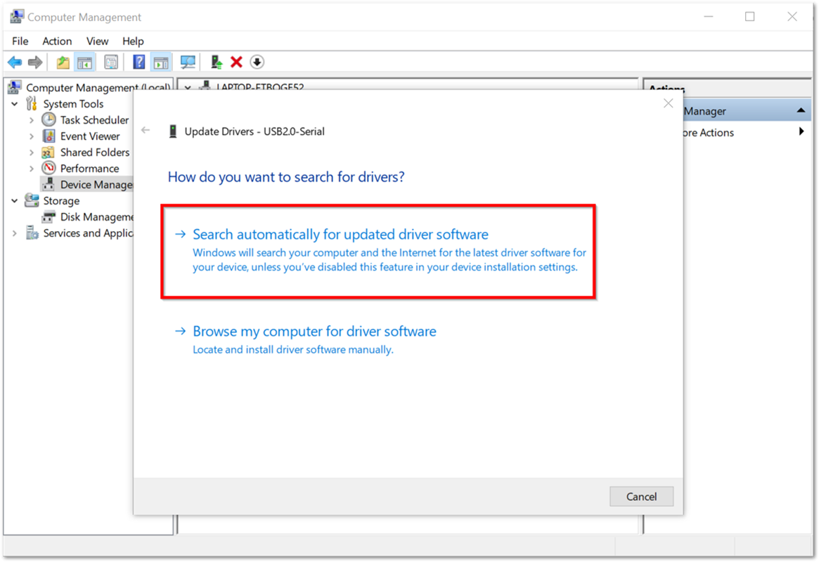 Figure 1: Automatic Driver Installation via Internet
- Wait for it to automatically download and install the missing driver. Once installation is done, USB-SERIAL CH340 must appear in the Ports (COM & LPT) drop down list. Take note of the COM Port associated with the driver as it will be used in the succeeding steps. For this sample process, the COM Port used by the USB-SERIAL CH340 driver is COM4.
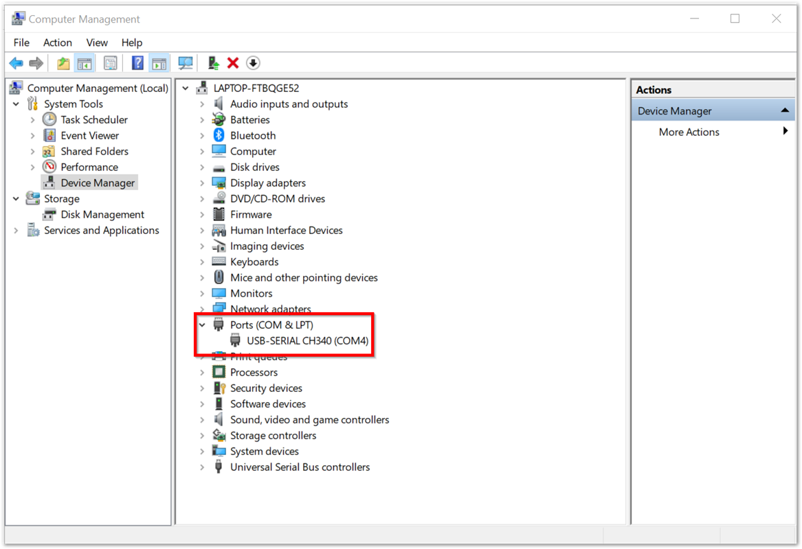 Figure 1: USB-SERIAL CH340 Driver Successfully Installed
In case the driver is still not installed upon doing the previous steps, download the driver manually at RAK downloads center.
- Test if your RAK7200 WisNode Track Lite can now communicate with the RAK Serial Port Tool. Configure the serial communication tool by selecting the proper port and configure the link as listed below and then click Open.
- COM: Choose the COM Port associated with the USB-SERIAL CH340 from the previous step. For this tutorial, the COM Port is COM4.
- Baud Rate: 115200 bps
- Data Bits: 8 bits
- Stop Bits: 1 bit
- Parity: NONE
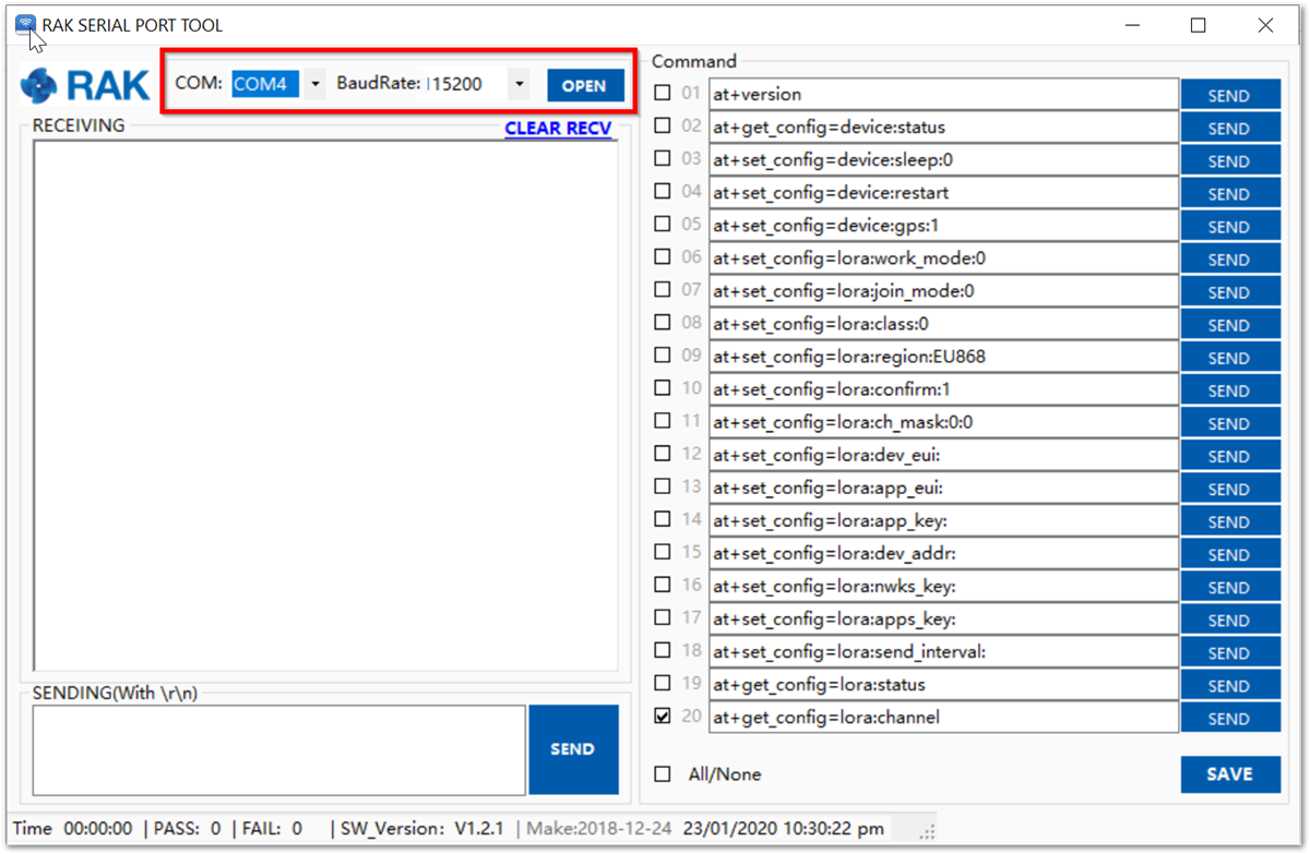 Figure 1: Connecting to the RAK Serial Port Tool
- Verify the connectivity by sending an AT Command. In the RAK Serial Port Tool, there are built-in AT+Commands within it at the right side. Send the following command to check the firmware version of your RAK7200 WisNode Track Lite. If connection is successful, the firmware version should appear same with Figure 6:
at+version
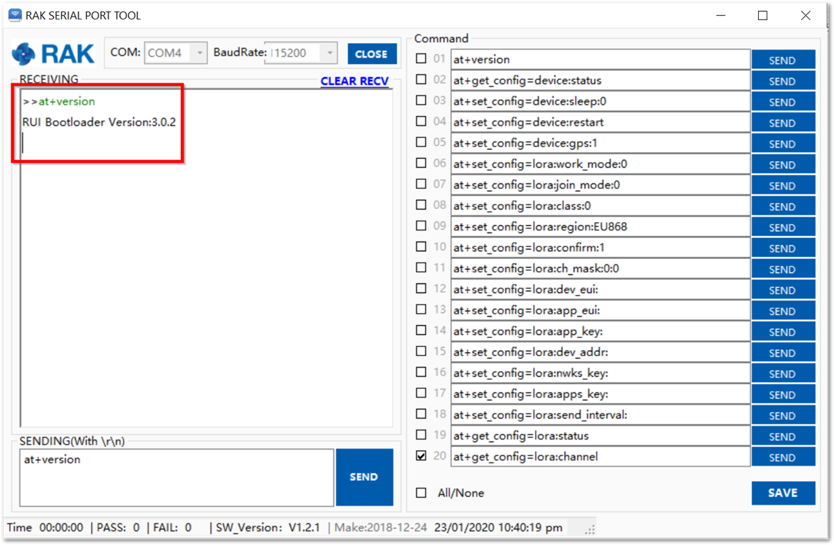 Figure 1: AT+Command Sample Serial Communication Test
Connecting to the Helium Network
Helium has quickly become the most widespread LPWAN communal network with more than 27,000 devices deployed globally. All the RAKwireless node products are compatible with it and the process of adding a device to the network is intuitive and straightforward.
This section will focus on giving a brief guide on how to connect the RAK7200 to the network console, assuming that there is a Helium Hotspot within range.
Log in or create your account in the Helium console page.
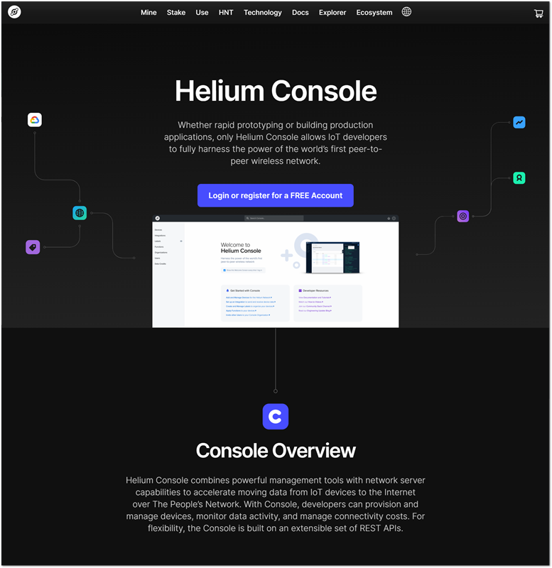 Figure 1: Helium console
Once registered/logged in, you will end up at the home page where you can see your function tree on the left and your DC balance at the top, as well as several useful links.
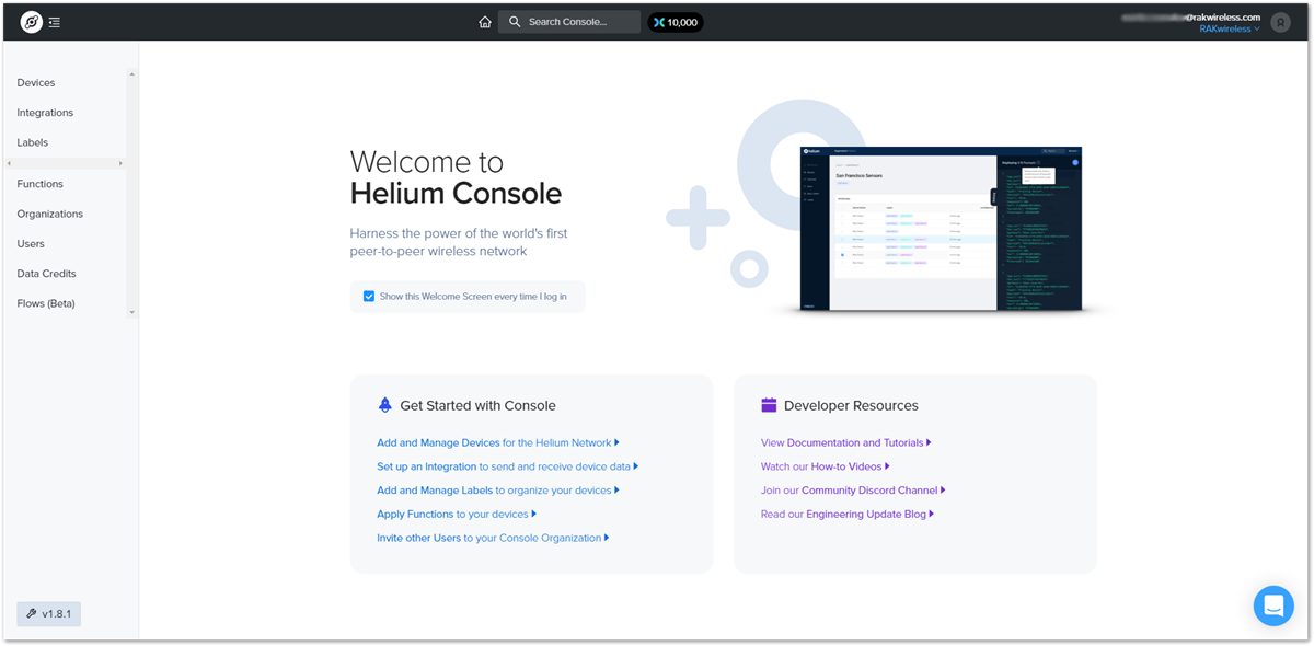 Figure 1: Helium console home screen
Go to the Devices section in the function tree. If this is your first time doing this, there will be no devices registered. Click the + Add Device button to get started.
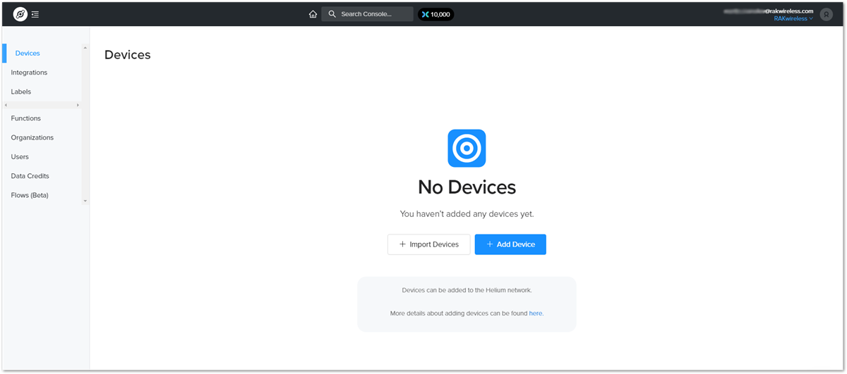 Figure 1: Devices section
A window will pop up with a set of a field containing the device parameters required for its registration.
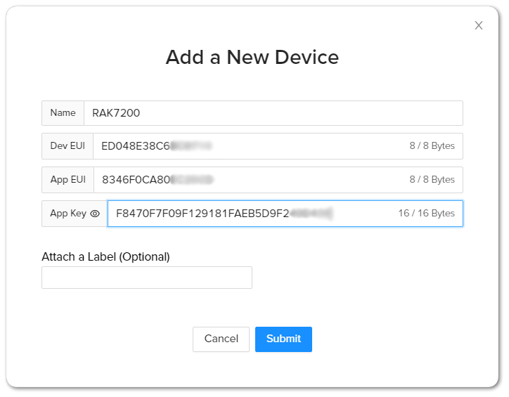 Figure 1: Adding a new device
Fill in a name of your choosing. The Dev EUI, App EUI, and App Key will have random values generated for you by default. Press the eye icon to reveal the values. You can manually replace them with values of your own. For this tutorial, use the default values. Press the Submit button, and you are done.
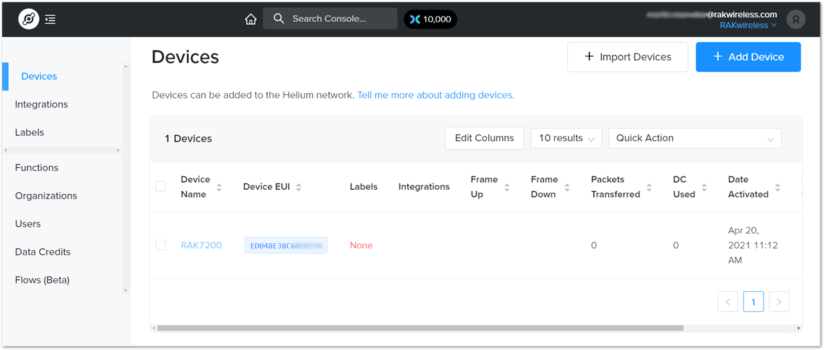 Figure 1: Helium devices
Now, your RAK7200 is registered and is awaiting activation. For this to happen, you need to import the Dev EUI, App EUI, and App Key in the RAK7200 using the RAK Serial Port Tool.
Open the tool, select the desired port (default baud rate) and open it. Then start importing your settings.
Configure your LoRa band and activation mode. This tutorial will be using the EU868 band and OTAA (the only option available for now with Helium) with device class A (default one, does not need configuring).
- Regional band and activation mode setting
at+set_config=lora:join_mode:0
at+set_config=lora:region:EU868
- Enter the Dev UI
Use the command below by replacing the XXXX with your Device EUI from the Helium console:
at+set_config=lora:dev_eui:XXXX
- Enter the App EUI
The same as with the Device EUI, replace the XXXX with your value:
at+set_config=lora:app_eui:XXXX
- Enter App Key
Finally, fill in the App key with the following command:
at++set_config=lora:app_key:XXXX
- Join Network
Finish executing the join command in order for the node to initiate the join procedure. Once the procedure is initiated and successfully complete, you will have a notification in the serial console.
at+join
 Figure 1: RAK7200 EUIs and key
If you take a look at the Helium console, you will also see the join request packets both in the graph and event log. Your node is now a part of the Helium Network.
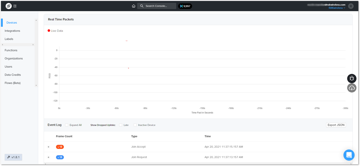 Figure 1: Helium console live device data
Connecting to The Things Network V3 (TTNv3)
At The Things Conference 2021, it was announced that The Things Network is upgrading to The Things Stack v3.
In this section, it will be shown how to connect RAK7200 WisNode Track Lite to The Things Stack.
First, log in to the TTNv3. To do so, head to the TTNv3 site. If you already have a TTN account, you can use your The Things ID credentials to log in.
 Figure 1: The Things Stack Home Page
 Figure 1: Console Page after a successful login
-
To connect RAK7200 WisNode Track Lite to TTNv3, you should already have connected a gateway in range to TTNv2 or TTNv3, or you have to be sure that you are in the range of a public gateway.
-
This tutorial is for EU868 Frequency band.
Adding an Application
- If you do not have created applications yet, to create an application, choose Create an application. If you have created applications before, navigate through Go to applications > + Add application.
 Figure 1: Create an application page
-
Fill in the needed information. After filling in, click Create application.
-
Owner - Automatically filled by The Things Stack, based on your account or created organization.
-
Application ID - This will be the unique ID of your application in the Network. ID must contain only lowercase letters, numbers, and dashes (-).
-
Application name (optional) - This is the name of your application.
-
Description (optional) – Description of your application. Optional application description; can also be used to save notes about the application.
-
 Figure 1: Create an application page
OTAA Mode
Register the Device
- From the Application Overview page, click on + Add end device.
 Figure 1: Adding a device in OTAA mode
- Below the Register end device heading, you can find two options for registering a device. Choose Manually.
- For Activation mode, choose Over the air activation (OTAA)
- For the LoRaWAN version, choose MAC V1.0.2 (RAK7200 is LoRaWAN 1.0.2 fully compliant).
 Figure 1: Registering the device in OTAA mode
- To get to the next step of the registration, click Start.
 Figure 1: Basic settings for OTAA mode
-
Fill in the Basic settings for the device:
-
End device ID - This is the unique identifier for your RAK7200 WisNode Track Lite in your application. You need to enter this manually. The End device ID must contain only lowercase letters, numbers, and dashes (-).
-
AppEUI - The AppEUI uniquely identifies the owner of the end device. It is provided by the device manufacturer. To get the AppEUI, connect your device via USB cable to your computer. Open RAK Serial Port Tool, choose the correct COM port and BaudRate, and run the following command:
at+get_config=lora:status Figure 1: AppEUI of the device
-
DevEUI - The unique identifier for this end device. It can be found on a sticker on the back of the device.
-
End device name (optional) - A unique, human-readable identifier for your device. You make it up, so be creative. Device IDs cannot be used by multiple devices within the same application.
-
End device description (optional) - Optional end device description; can also be used to save notes about the end device.
-
-
Click Network layer setting.
 Figure 1: Network layer setting for OTAA mode
 -
Here you must configure the Network layer settings for the device:
-
Frequency plan - The frequency plan used by the end device. Note that, for this tutorial, the frequency plan used is Europe 863-870 MHz (SF9 for RX2 – recommended).
-
Regional Parameters version - The Regional Parameters specify frequency, dwell time, and other communication settings for different geographical areas. The Regional Parameters version is the version of the LoRa Alliance specification which your device supports. This should be provided by the device manufacturer in a datasheet. For this example, PHY V1.0.2 REV A is chosen.
-
LoRaWAN class capabilities – Here you can select if your device supports Class B, Class C, or both.
-
In Advanced settings, you can configure additional settings for your device.
 Figure 1: Advanced network layer settings of the device
For this example, these settings will be left as default.
-
Click Join settings.
 Figure 1: Join settings for OTAA mode
 -
Fill in the Application key (AppKey) to secure communication between the end device and the application. The AppKey can be generated automatically by clicking the Generate button next to the AppKey field.
 Figure 1: Generate the AppKey
 -
In the Advanced settings, you can configure more options about your device.
 Figure 1: Advanced join settings for OTAA mode
For this example, these settings will be left as default.
- Finally, to finish registering your device, click Add end device.
Configuring the Device in OTAA Mode
-
For configuring the node, you will need the following three parameters: Device EUI, Application EUI, and Application Key. You can see them all on the Device Overview page. But since the two EUI's come with the device, you only need the Application Key from there.
 Figure 1: OTAA device parameters
 -
Using the RAK Serial Port Tool, set the join mode, device class, and your LoRaWAN region to your correct frequency band, with the following set of AT commands:
- For the join mode (OTAA):
at+set_config=lora:join_mode:0
- For the class (Class A):
at+set_config=lora:class:0
- For the region:
at+set_config=lora:region:EU868
Remember to replace the frequency band with the one for your LoRaWAN region. Check first your frequency plan.
 Figure 1: Setting up the RAK7200 WisNode Track Lite operation mode
The following tutorial is based on using the EU868 frequency band.
- Now that those parameters are set, enter the App Key, using the command below. Remember to replace the XXXX with the corresponding parameter value for your particular case.
at+set_config=lora:app_key:XXXX
 Figure 1: Setting up the RAK7200 WisNode Track Lite OTAA parameters
- Finally, execute the join command:
at+join
 Figure 1: Join command
If you get a response in the Live data feed in The Things Stack, it means your RAK7200 is successfully connected!
 Figure 1: Sending data to The Things Stack from RAK7200 WisNode Track Lite
Connecting with ChirpStack
In this section, a practical exercise will be performed to show how to connect the RAK7200 module to the ChirpStack platform.
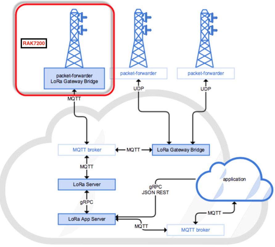 Figure 1: RAK7200 module in the context of the ChirpStack platform
The ChirpStack or previously known as LoRaServer project provides open-source components for building LoRaWAN networks. Like the case of TTN, the RAK7200 module is located in the periphery and transmit the data to the backend servers through a LoRa gateway. Learn more about ChirpStack.
In this document, it is assumed that you are using a RAK LoRa gateway, such as RAK7249. The gateway must be configured and registered previously to Chirpstack deployment. For further information, check the RAK documents for more details.
You can provide your own Chirpstack deployment or use the one provided by RAK for testing purposes. RAK has enabled a set of LoRaServer on the cloud to support customers to test their RAK LoRa gateway or RAK LoRa node. Table below shows the IP address for the supported regions. Submit your request in the following URL to get an account and password.
| Frequency | IP Address |
|---|---|
| CN470 | 106.15.233.112 |
| EU868 | 47.88.62.184 |
| US915 | 106.15.239.64 |
| AS923 | 47.101.11.150 |
| IN865 | 139.155.10.119 |
In this section, you need the following requirements:
- Have an account at the ChirpStack deployment provided by RAK.
- Have access to a LoRaWAN gateway registered at the RAK’s ChirpStack server.
- Serial Port Tool provided by RAK.
- RAK7200 module
Before you start, you must choose which mode you are going to use, whether in OTAA or ABP mode, to register the device to the network server.
Sign up and loginRequest an account in the forum of RAK, then access to server assigned for your region with your username and password.
Create a New Application
- Go to the Application section as shown in Figure 33.
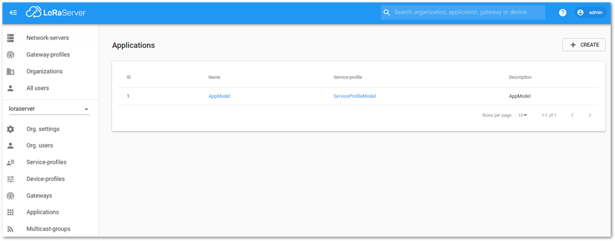 Figure 1: Application Section of ChirpStack LoRaServer
- By default, you should create a new Application, although you can reuse the existing ones. For this setup, create a new Application by clicking on the CREATE button, and fill the required parameters as shown in Figures 34 and 35.
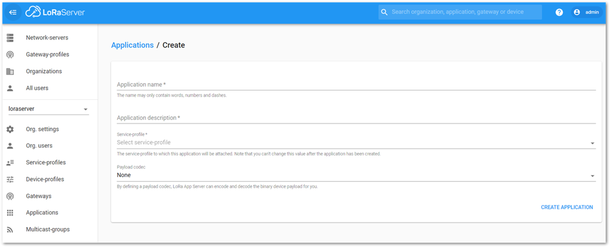 Figure 1: Creating a New Application
- For this setup, create an Application named RAK7200_test.
ChirpStack LoraServer supports multiple system configurations, with only one by default.
- Service profile: field is to select the system profile.
- Payload codec: is the parsing method for selecting load data. Such as parsing LPP format data.
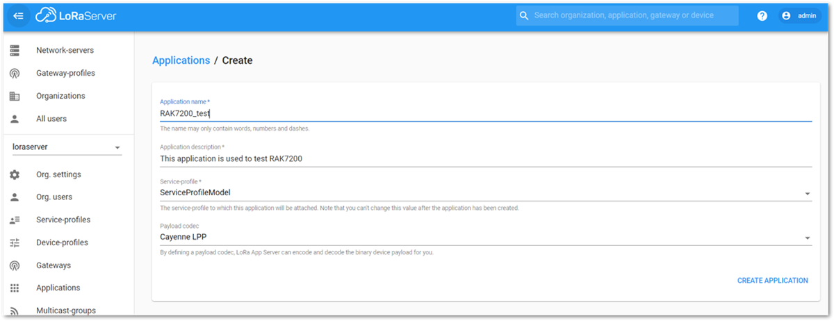 Figure 1: Filling Parameters of an Application
- Choose the Application created in the previous step, then select the DEVICES tab as shown in Figures 36 and 37.
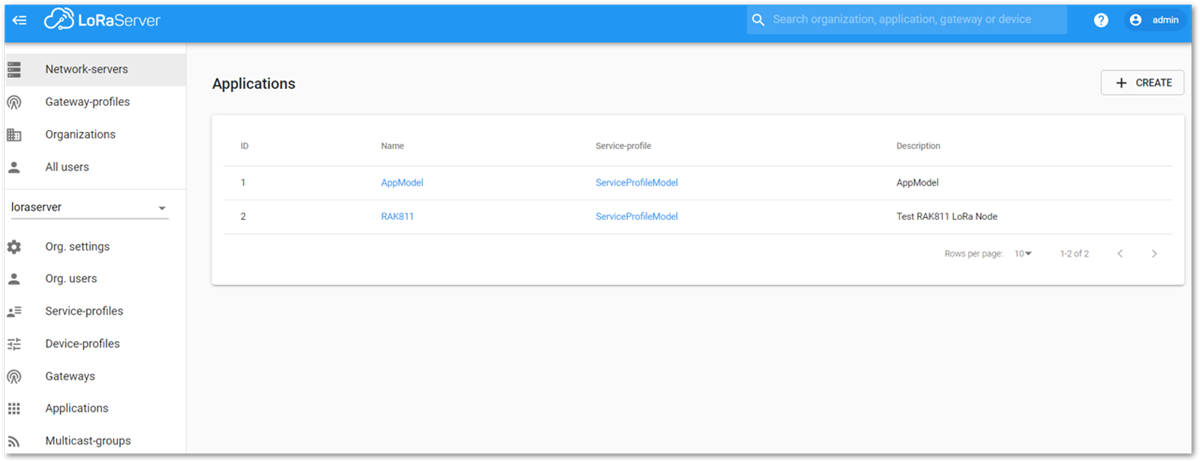 Figure 1: List of Applications Created
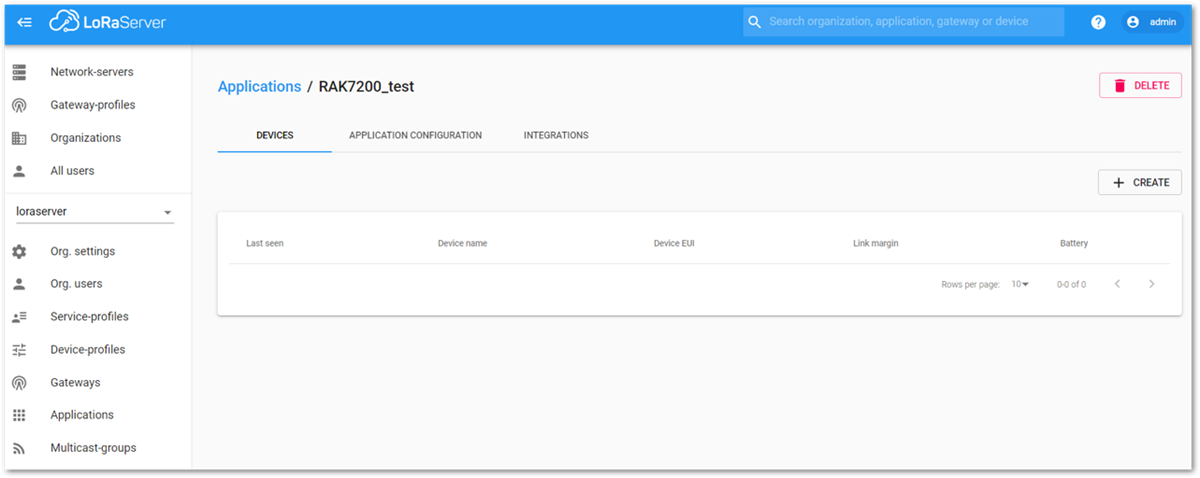 Figure 1: Device Tab of an Application
- Once inside of the DEVICE tab, create a new device (LoRa node) by clicking on the + CREATE button.
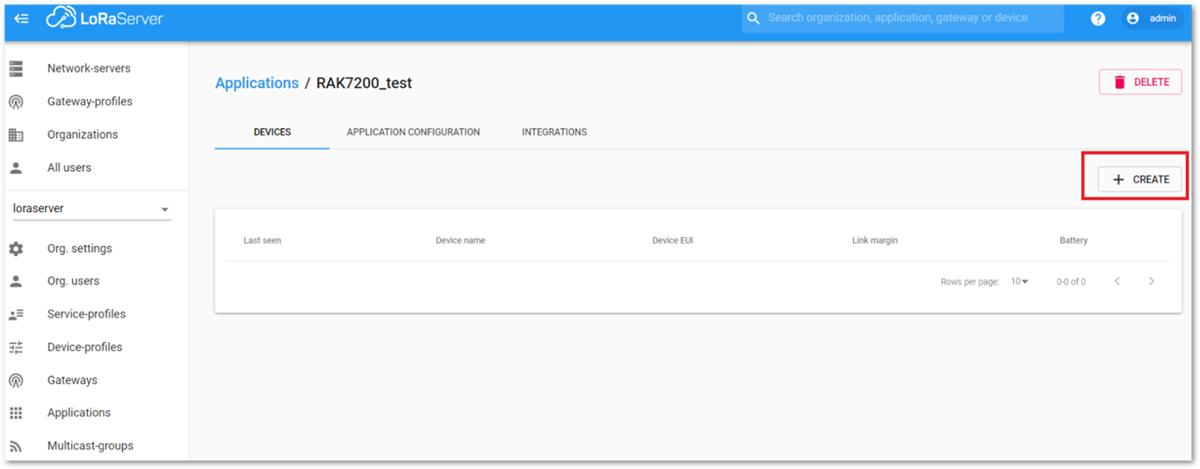 Figure 1: Add a New Device at Device Tab
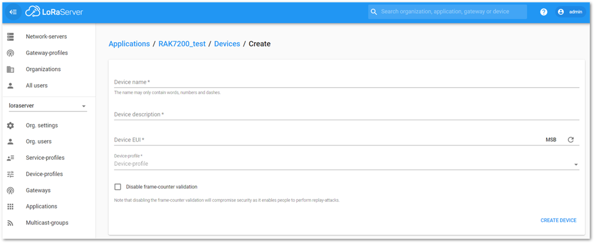 Figure 1: New Device Registration Form
- Once the node is created, fill-in the necessary data. You can generate a Device EUI automatically by clicking the following icon, or you can write a correct Device EUI in the edit box.
- Device name and Device description: These are descriptive texts about your device.
- Device EUI: This interface allows you to generate a Device EUI automatically by clicking the icon highlighted in red in Figure 40. You can also add a specific Device EUI directly in the form.
- Device Profile:
- If you want to join in OTAA mode, select DeviceProfile_OTAA.
- If you want to join in ABP mode, select DeviceProfile_ABP.
ChirpStack does not support AS923 in ABP mode.
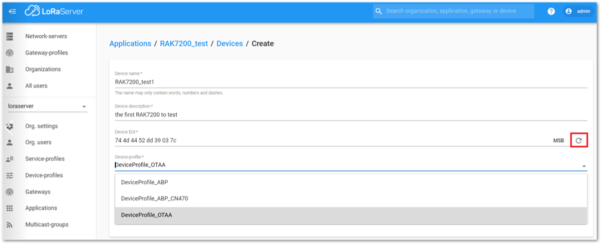 Figure 1: Generate a New Device EUI
LoRaWAN Join Mode
In LoRaWAN, there are two ways a node can connect itself to the LoRaWAN network. This is referred to as Join Mode. LoRaWAN allows the OTAA mode and the ABP mode. In this section, the configuration process of these two modes, both on the platform side and the node side will be explained.
OTAA Mode
Configure the OTAA Mode on the Platform
- If you have selected DeviceProfile_OTAA as shown in Figure 41, then after the device is created, an Application Key must be also created for this device.
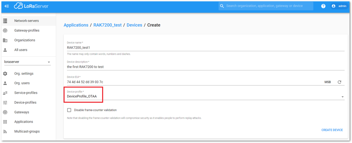 Figure 1: Chirpstack OTAA Activation
- A previously created Application Key can be entered here, or a new one can be generated automatically by clicking the icon highlighted in red in Figure 42:
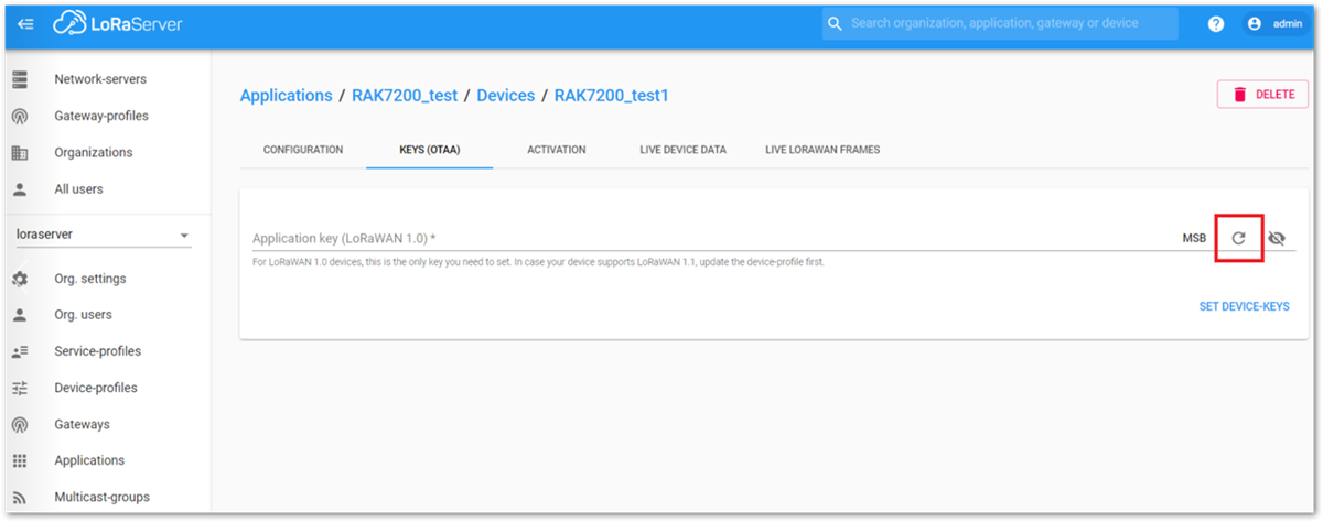 Figure 1: Chirpstack OTAA Set Application Keys
- Once the Application Key is added in the form, the process can be finalized by clicking on the SET DEVICE-KEYS button.
- As shown in Figure 43, a new device should be listed in the DEVICES tab. The most important parameters, such as the Device EUI are shown in the summary.
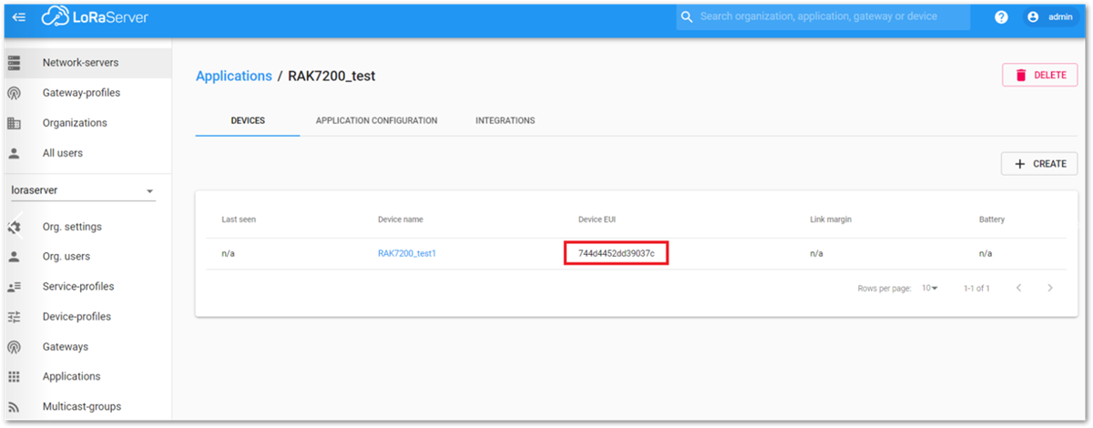 Figure 1: Chirpstack OTAA List of Device
- To end the process, it is a good practice to review that the Application Key is properly associated with this device. The Application Key can be verified in the KEYS(OTAA) tab as shown in Figure 44.
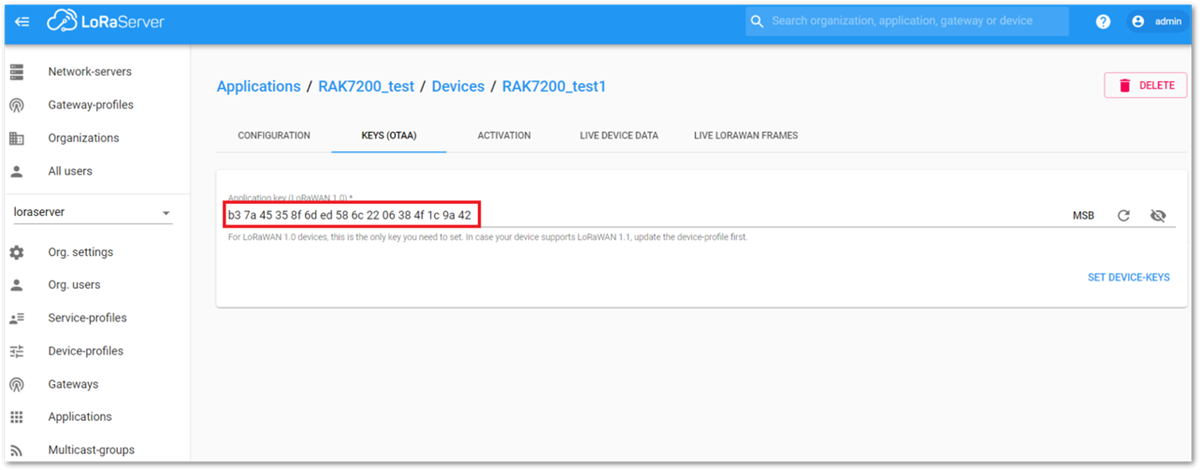 Figure 1: Chirpstack OTAA Set Application Key
Standard OTAA mode requires the Device EUI, Application Key, and the Application EUI. But in the ChirpStack’s implementation, only the Device EUI and the Application Key are mandatory. The Application EUI is not required and is not recorded in the Application tab. Nevertheless, the Application EUI is a mandatory parameter in the RAK7200 module’s firmware. To resolve this mismatch, you can reuse the Device EUI as the Application EUI during the configuration in the side of the node.
Configure the OTAA mode on the RAK7200
The RAK7200 module supports a series of AT commands to configure its internal parameters and control the functionalities of the module.
To set up the RAK7200 module to join ChirpStack using OTAA start by connecting the RAK7200 module to the Computer (see Figure 1) and open the RAK Serial Port Tool, wait for the communication to start. It is recommended to test the serial communication by sending either of these two AT commands:
at+get_config=lora:status
at+version
As an example, these are the list of the parameters you need to configure in RAK7200:
- LoRa join mode: OTAA
- LoRa class: Class A
- LoRa region: AU915
- Device EUI: 744d4452dd39037c
- Application EUI: 70B3D57ED001C544
- Application Key: 4E2003296FC5CD26F46940A6DAFA9D1
- Set the LoRa join mode to OTAA.
at+set_config=lora:join_mode:0
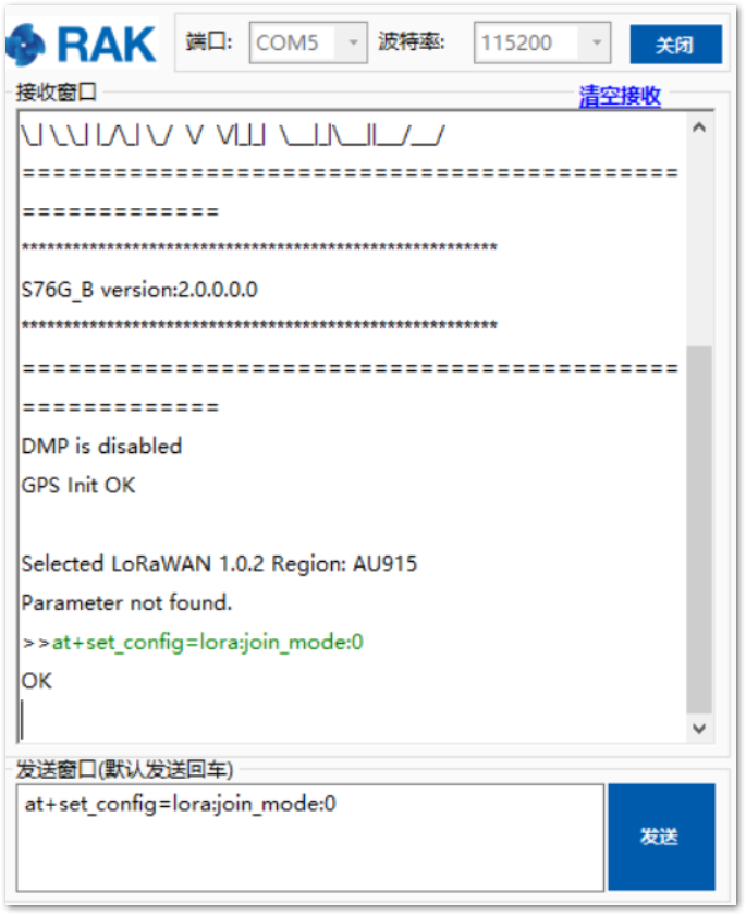 Figure 1: Setting LoRa Join Mode to OTAA Mode
- Set the LoRa class to Class A.
at+set_config=lora:class:0
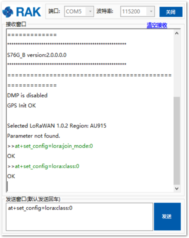 Figure 1: Setting LoRa Class Parameter
- Set the frequency/region to AU915.
- Refer in the RAK7200 Datasheet for the list of supported frequencies.
at+set_config=lora:region:AU915
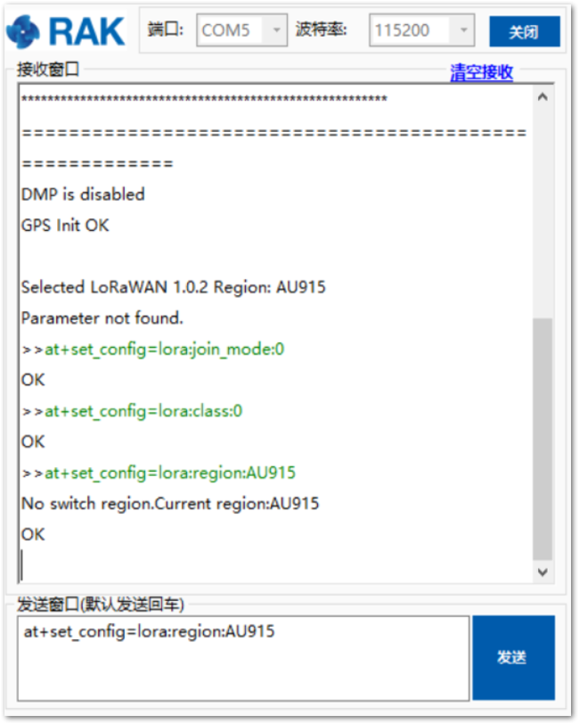 Figure 1: Setting LoRa Frequency/Region Parameter
- Set the Device EUI.
at+set_config=lora:dev_eui:744d4452dd39037c
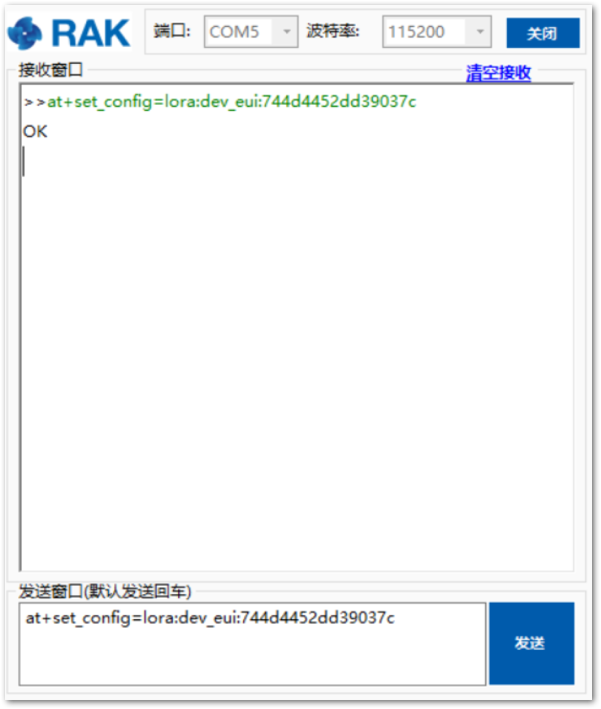 Figure 1: Setting LoRa Device EUI Parameter
- Set the Application EUI.
at+set_config=lora:app_eui:70B3D57ED001C544
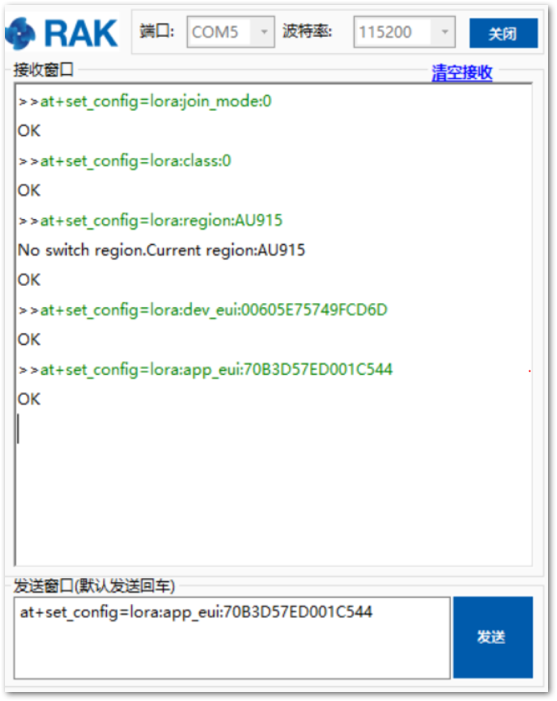 Figure 1: Setting LoRa Application EUI Parameter
Remember, the Application EUI parameter was not required in the ChirpStack platform. Therefore, it is possible to use the same ID as the Device EUI. Otherwise, the firmware will complain.
- Set the Application Key.
- Get the Application Key from the TTN register.
at+set_config=lora:app_key:4E2003296FC5CD26F46940A6DAFA9D1
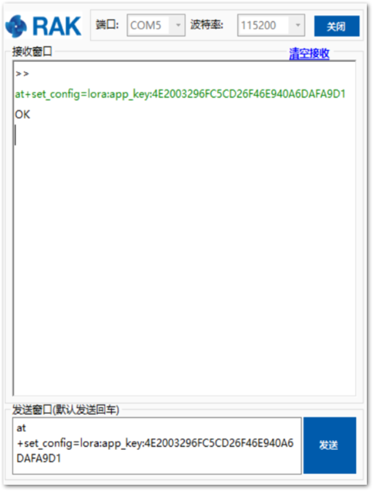 Figure 1: Setting LoRa Application Key Parameter
After configuring all parameters, you need to reset RAK7200 Module to save the parameters.
- After resetting, start to join.
at+join
After 5 or 6 seconds, if the request was successfully received by a LoRa gateway, then you should see the messages shown in Figure 51.
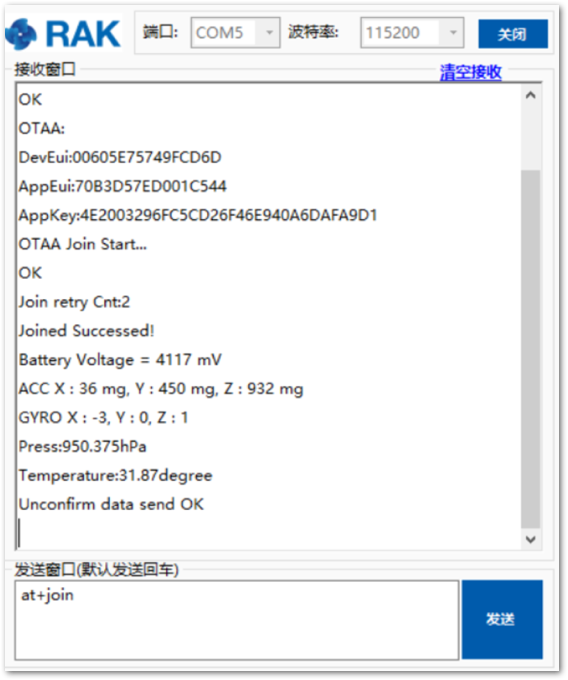 Figure 1: Chirpstack OTAA Join the Network via RAK Serial Port Tool
- You can then see the JoinRequest and JoinAccept on ChirpStack page.
 Figure 1: Checking LoRaWAN Joint Request in Chirpstack OTAA Console
- On the ChirpStack platform, you should also see the messages in the LORAWAN FRAMES tab as shown in Figure 52.
By convention, messages sent from nodes to gateways are considered as Uplinks. While messages sent by gateways to nodes are considered as Downlinks.
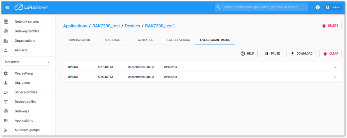 Figure 1: Chirpstack Data Received Preview
This concludes the exercise to send data in the OTAA mode.
ABP Mode
Configure the ABP Mode on the Platform
During the registration of a new device, if you select DeviceProfile_ABP or DeviceProfile_ABP_CN470, as shown in Figure 54, then the ChirpStack platform will assume that this device will join to the LoRaWAN network using the ABP mode.
Check Disable counting frame verification. During the test, when the module is restarted, the frame counting number will be also be restarted from zero. This would cause a synchronization problem with the ChirpStack server treating it as a replay attack. For the testing purpose, it is safe to disable this feature, but remember to activate it in a production environment.
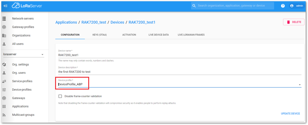 Figure 1: ChirpStack Console, Configuring a Device
After selecting the ABP mode, the following parameters appear in the Activation tab:
- Device address
- Network Session Key
- Application Session Key
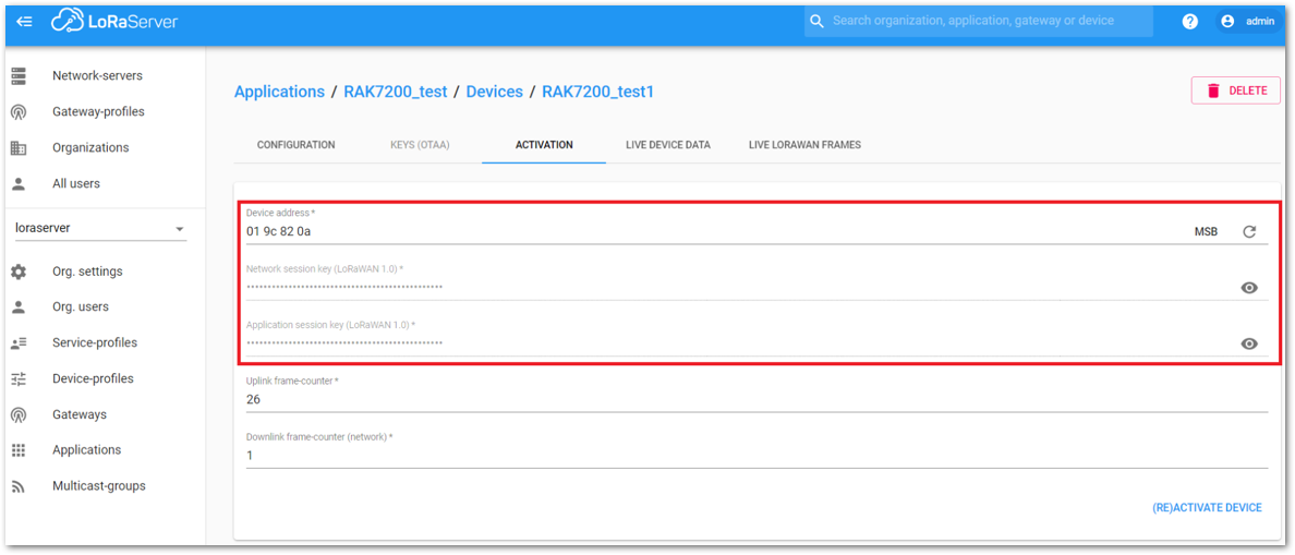 Figure 1: Chirpstack ABP Activation Parameters Needed
- The parameters can be generated as random numbers by the platform or can be set with user values. Once these parameters are filled properly, the process is completed by clicking on the ACTIVATE DEVICE button.
Configure the ABP mode on the RAK7200
In the following steps, you will configure the RAK7200 module to work in the ABP mode. To set up the RAK7200 module to join ChirpStack using ABP start by connecting the RAK7200 module to the Computer (see Figure 1) and open the RAK Serial Port Tool, wait for the communication to start. It is recommended to test the serial communication by sending either of these two AT commands:
at+get_config=lora:status
at+version
As an example, these are the list of the parameters you need to configure in RAK7200:
- LoRa join mode: ABP
- LoRa class: Class A
- LoRa region: AU915
- Device address: 019c820a
- Network Session Key: 34fb174daa6dc34733495f73bd2b1ba1
- Application Session Key: d7fde8da53ded21216fe71d4f91ecf0e
- Set LoRa join mode to ABP.
at+set_config=lora:join_mode:1
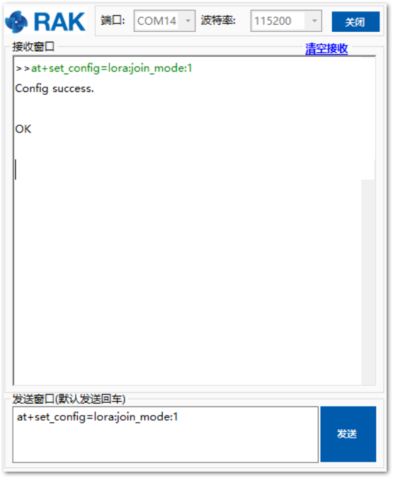 Figure 1: Setting LoRa Join Mode to ABP Mode
- Set LoRa class to Class A.
at+set_config=lora:class:0
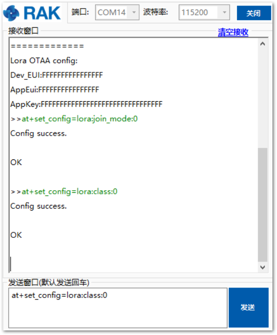 Figure 1: Setting LoRa Class Parameter
- Set the frequency/region to AU915.
- Refer in the RAK7200 Datasheet for the list of supported frequencies.
at+set_config=lora:region:AU915
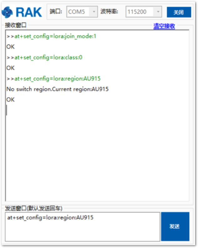 Figure 1: Setting LoRa Class Parameter
- Set the Device Address.
at+set_config=lora:dev_addr:019c820a
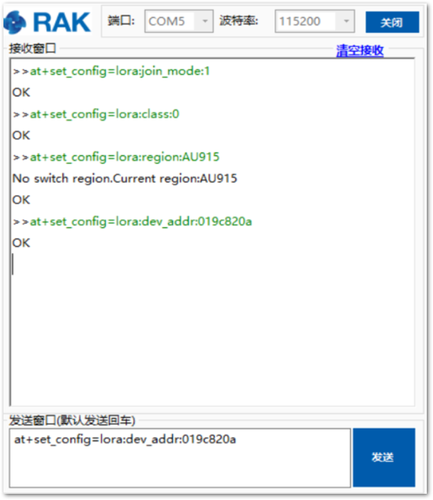 Figure 1: Setting LoRa Device Address Parameter
- Set the Network Session Key.
at+set_config=lora:nwks_key:34fb174daa6dc34733495f73bd2b1ba1
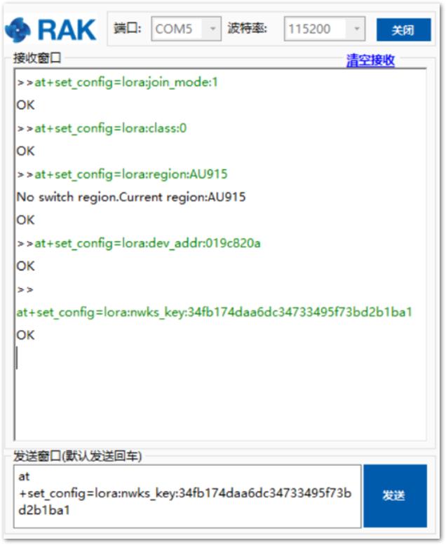 Figure 1: Setting LoRa Network Session Parameter
- Set the Application Session Key.
at+set_config=lora:apps_key: d7fde8da53ded21216fe71d4f91ecf0e
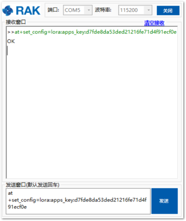 Figure 1: Setting LoRa Network Session Parameter
After configuring all parameters, you need to reset RAK7200 Module for saving parameters.
- After resetting RAK7200 Module, join in ABP mode.
at+join
By using the ABP mode in LoRaWAN protocol, it doesn’t require to join a network before sending LoRaWAN package. But to keep the consistency of internal states of the firmware of the RAK7200 module, it still required to send at+join command in the ABP mode. This time, the firmware should reply almost immediately with an OK.
Once the RAK7200 joined into a LoRaWAN network, it will start to send periodically the data collected from the GPS and other sensors. Then, go to the ChirpStack platform to confirm that the messages ware properly received as shown in Figure 62.
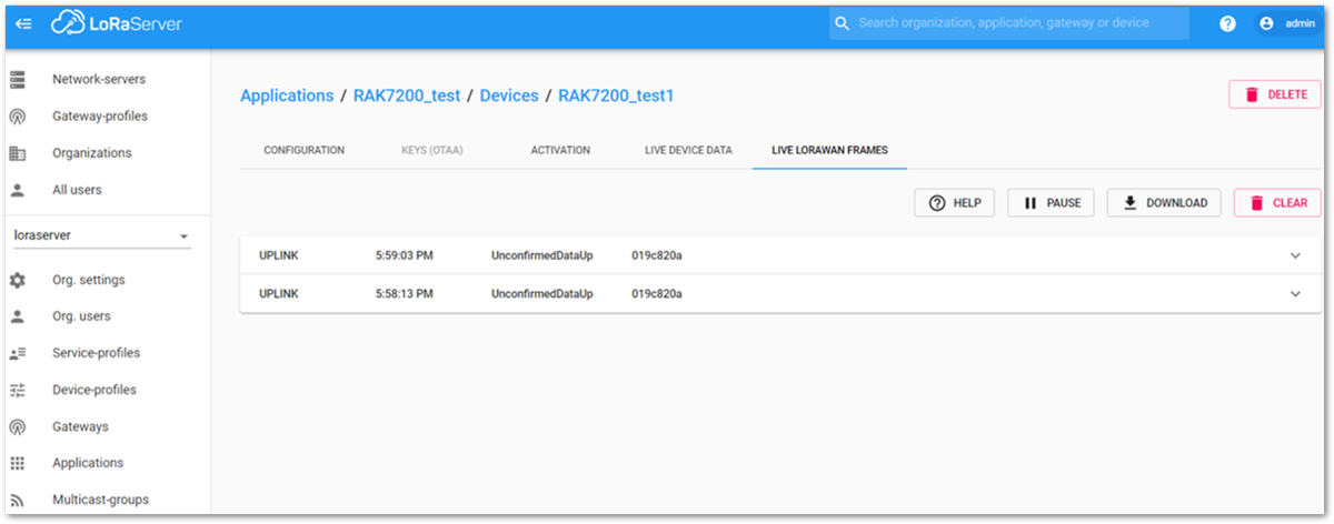 Figure 1: Data Collected in ChirpStack
Miscellaneous
Upgrading the Firmware
Before you start working with the RAK7200, it is recommended to keep the RAK7200 module updated to the latest version of the firmware. Download the latest RAK7200 firmware.
In this section, you will upgrade the firmware by using the STM32CubeProgrammer provided by STM32. Execute the following steps in upgrading the firmware.
-
Install the STM32CubeProgrammer tool on your Windows PC.
-
Connect the RAK7200 module to the USB interface of a general-purpose computer as shown in Figure 1.
-
To program the firmware, the RAK7200 module must be entered into the boot mode. You can achieve it by following this procedure:
- Hold down the BOOT0 button, and then press the Reset button.
- Release the Reset button, then release the BOOT0 button.
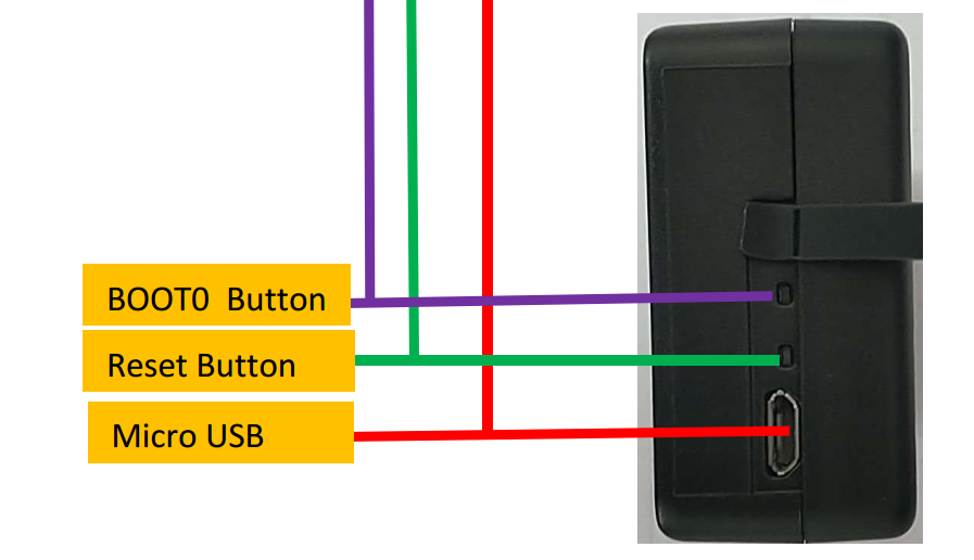 Figure 1: RAK7200 BOOT0 and Reset buttons
- Open the STM32CubeProgrammer tool and select the UART as the type of connection to the RAK7200 module. Then, configure the following communication parameters:
- Port: choose the port assigned by the operative system
- Baud rate: 115200.
- Parity: Even
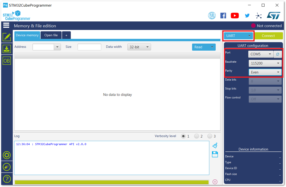 Figure 1: STM32CubeProgrammer UART Communication Parameters
- Once the connection parameters were properly set, press the Connect button located at the top right corner. If there were problems during the connection, the errors would be shown in Log message box. The usual problem is because the RAK7200 didn’t entered into the boot mode properly. In such cases, you will find similar error messages shown in Figure 65.
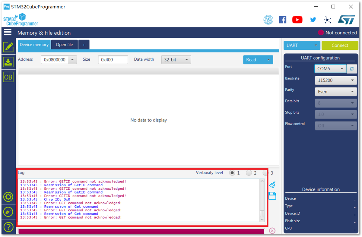 Figure 1: Error Messages Received when not in Boot Mode
- After connecting successfully, the STM32CubeProgrammer will display Data read successfully in the log message box.
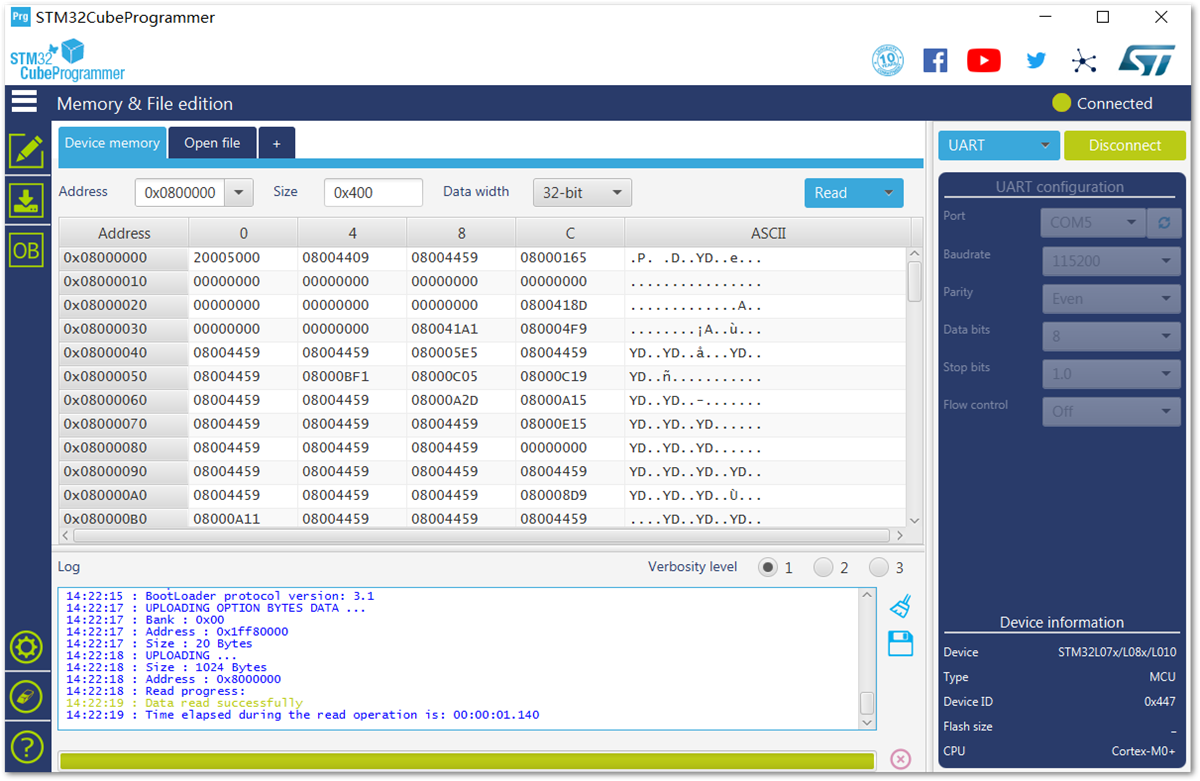 Figure 1: Messages Received when connected in Boot Mode
- Once the communication is established with the RAK7200, burn a newer version of firmware into the RAK7200 module:
- Erase the existing data: To avoid unexpected problems during the future usage of the module, it’s a good practice to erase completely the EEPROM before burning the new version of firmware. You can achieve it by clicking on the Erase button highlighted in red square in Figure 67.
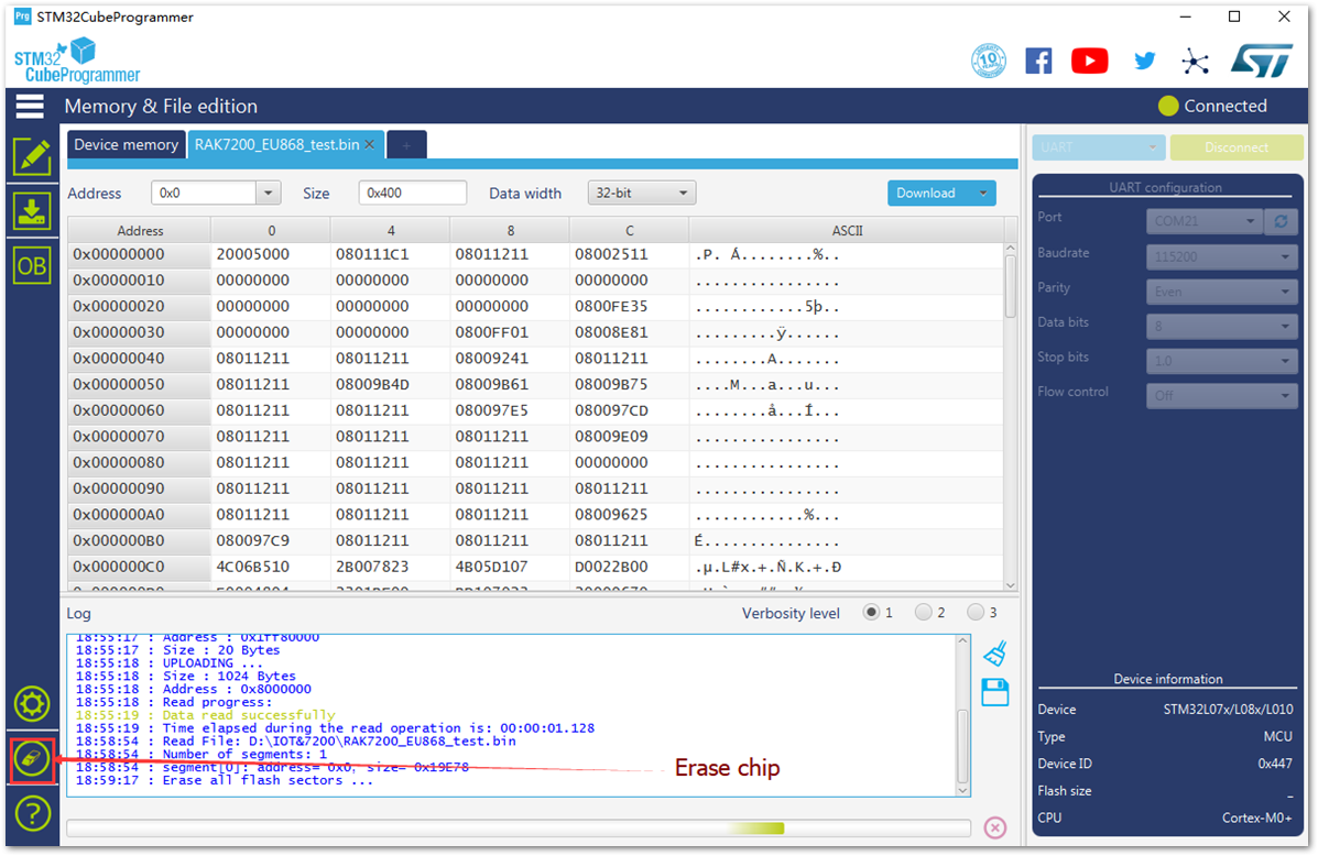 Figure 1: STM32CubeProgrammer Erase Button
- Select the desired firmware to burn: Press the Open file tab, see Figure 66, and select the correct firmware file in the pop-up window as shown in Figure 68.
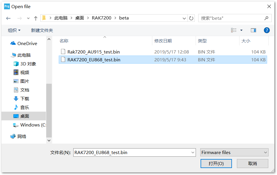 Figure 1: STM32CubeProgrammer Select New Firmware
- Once the new firmware is loaded, its content is displayed in the tool in hexadecimal format. Now, As shown in Figure 69, press the Download button to start the burning process. Once finished, a pop-up message will appear.
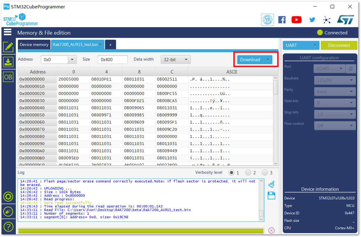 Figure 1: Download or save the new firmware
- To finalize the firmware upgrade process, Disconnect and close the STM32CubeProgrammer tool.
Don’t forget to reset the module in order to exit from the boot mode.
