WisBlock Biometric Monitoring Kit Quick Start Guide
Prerequisite
What Do You Need?
The WisBlock IoT Education Kit - Medical Kit comes with RAK19007 and RAK19003 WisBlock Base boards, two RAK4631 WisBlock Core modules, and set of sensor modules to explore with. Before going through each and every step on using the WisBlock IoT Education Kit - Medical Kit, make sure to prepare the necessary items listed below:
Hardware
- RAK4631 WisBlock Core
- RAK19007 WisBlock Base Board
- RAK19003 WisBlock Base Board
- RAK12003 Temperature Sensor
- RAK12012 Heart Rate Sensor
- USB C Cable
- RAK19005 Sensor Extension Cable (optional)
- RAK19008 IO Extension Cable (optional)
- Li-Ion/LiPo battery (optional)
- Solar charger (optional)
Software
Arduino
- Download and install the ArduinoIDE.
- To add the RAKwireless Core boards on your Arduino Boards Manager, install the RAKwireless Arduino BSP.
Product Configuration
Hardware Setup & Sample Applications
The WisBlock IoT Education Kit - Medical Kit includes temperature and heart rate sensors that can be used with the RAK19007 and RAK19003 WisBlock Base boards. This kit will teach you how to measure a person's temperature and heart rate without making any physical contact with them. Below is a sample application of these sensors.
- Biometric Monitoring - RAK4631 + RAK12003 + RAK12012
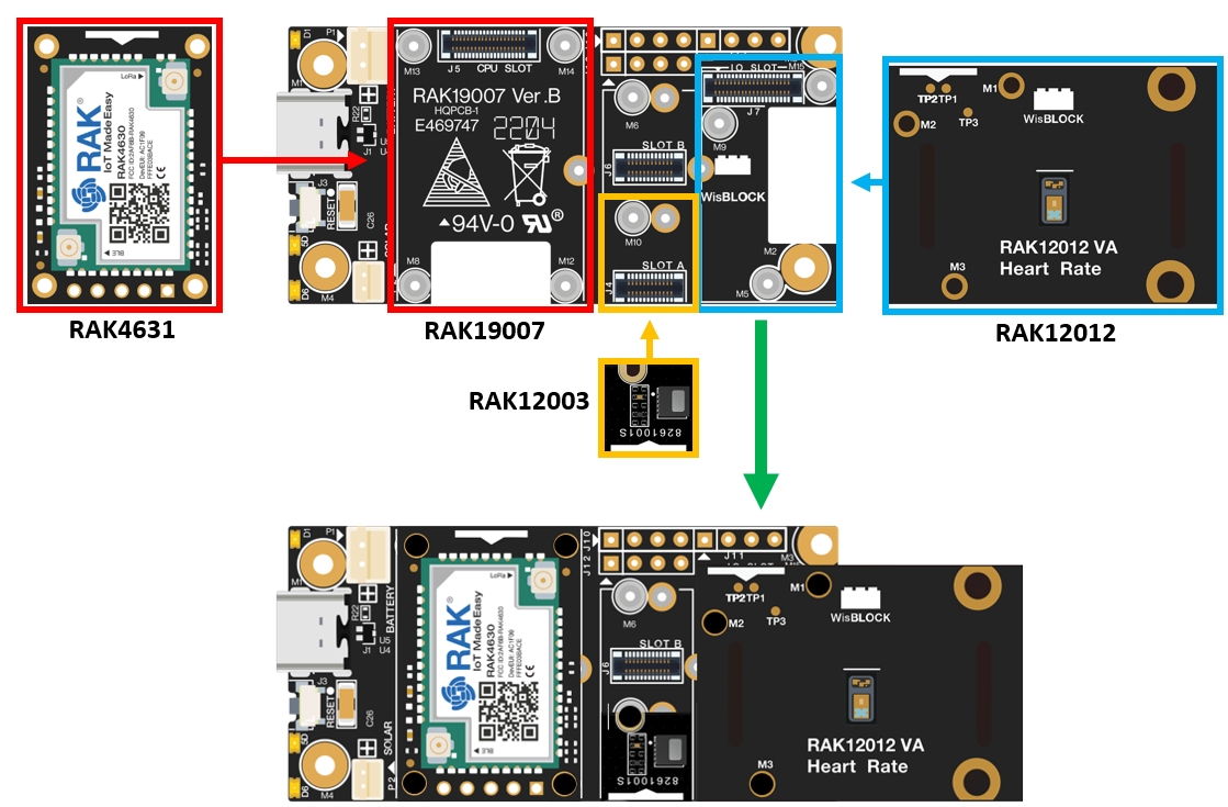 Figure 1: RAK4631 + RAK12003 + RAK12012
Assembly and Functionality Tests of WisBlock Medical Modules
This kit incorporates the WisBlock Medical modules listed below. Refer to the links below for more information on their assemblies and functionalities:
Software Configuration and Examples
LoRaWAN Application for WisBlock IoT Education Kit - Medical Kit Using TTN and qubitro�
Biometric Monitoring LoRaWAN Application
The Biometric Monitoring LoRaWAN Application monitors an individual's temperature and heart rate. It employs the RAK12003 temperature sensor based on MLX90632 from Melexis. Also, it uses the RAK12012 heart rate sensor based on the MAX30102 chip from Analog Devices.
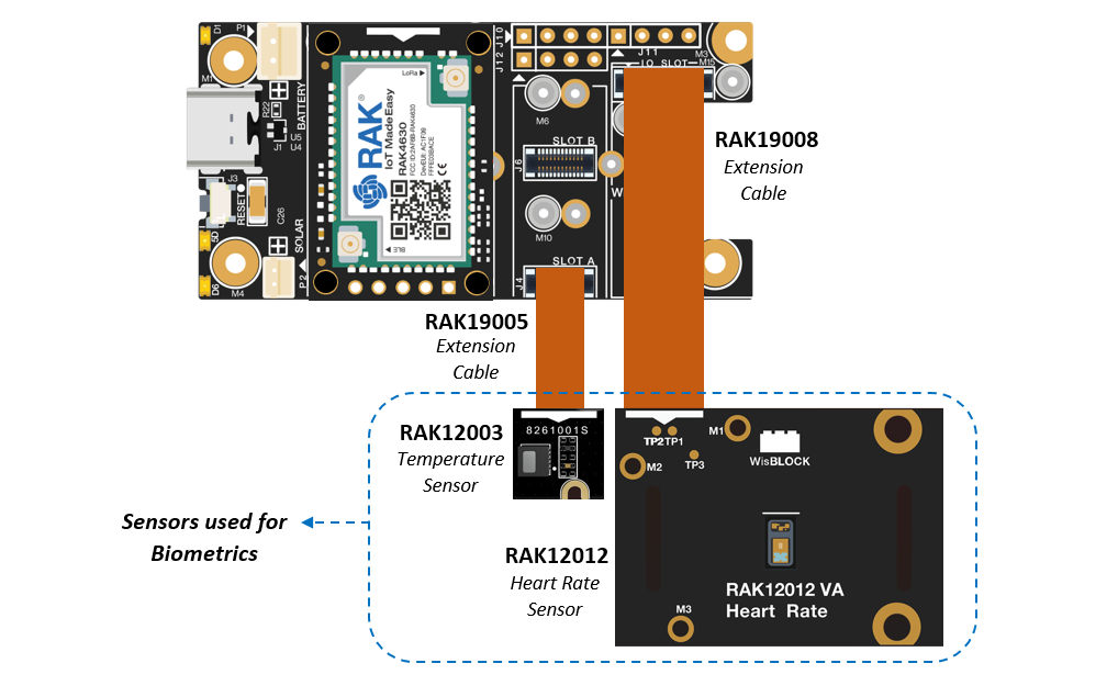 Figure 1: Biometric Monitoring device
Biometric Monitoring - TTN Registration
- The first step is to go to The Things Network. If you don't have an account yet, sign up and then select a cluster.
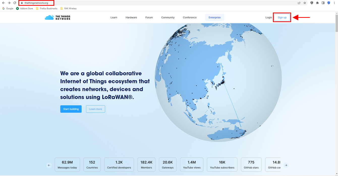 Figure 1: Signing up an account in TTN
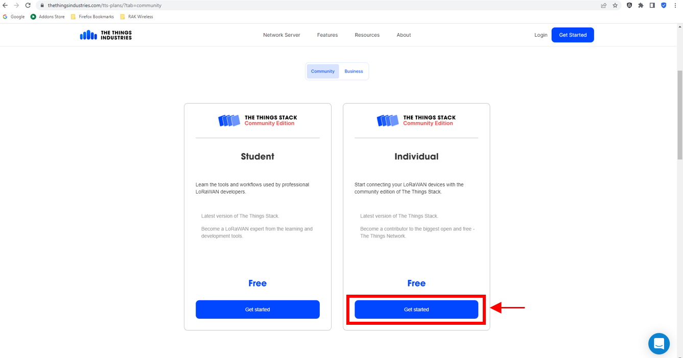 Figure 1: Signing up an account in TTN
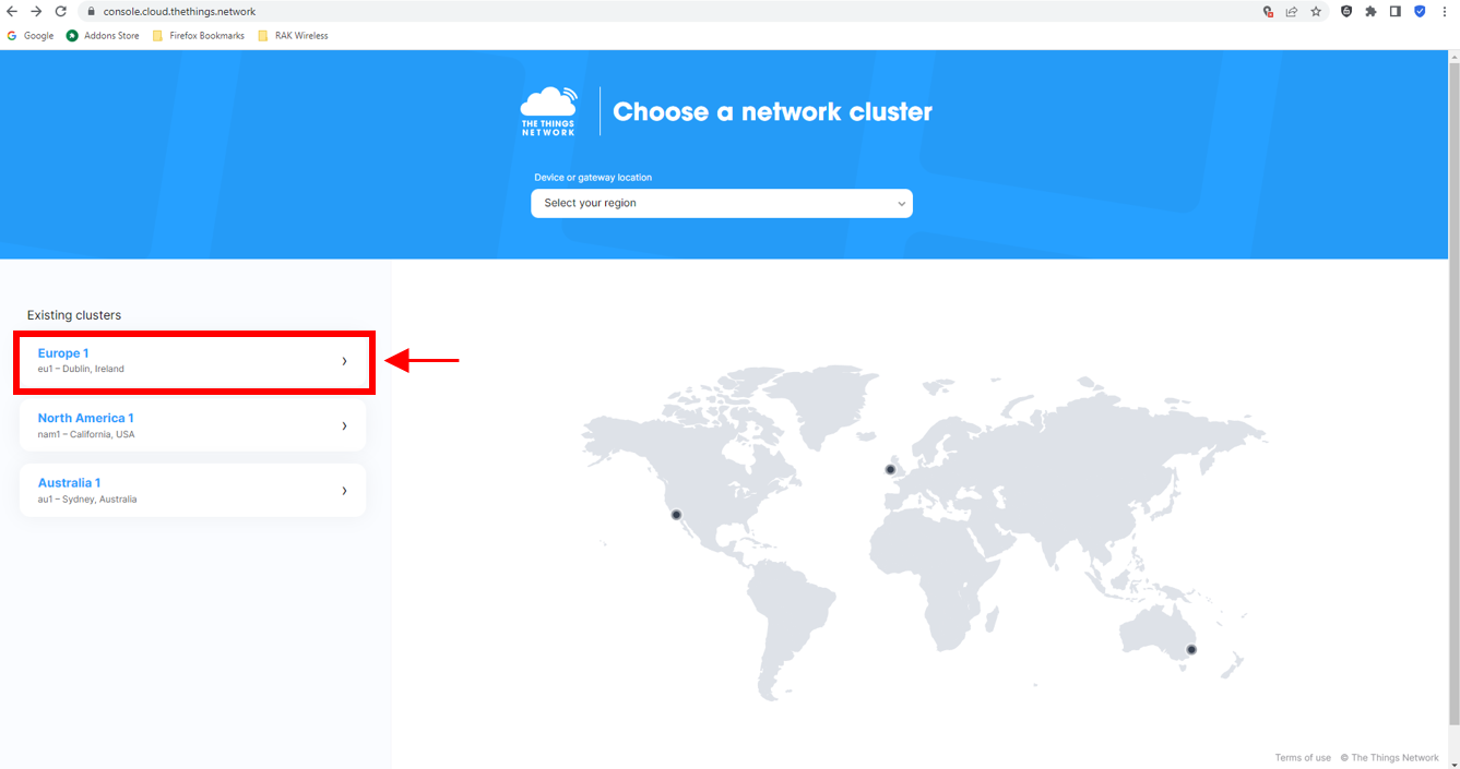 Figure 1: Selecting Cluster in TTN
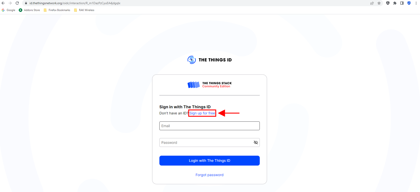 Figure 1: Signing up through the Things ID
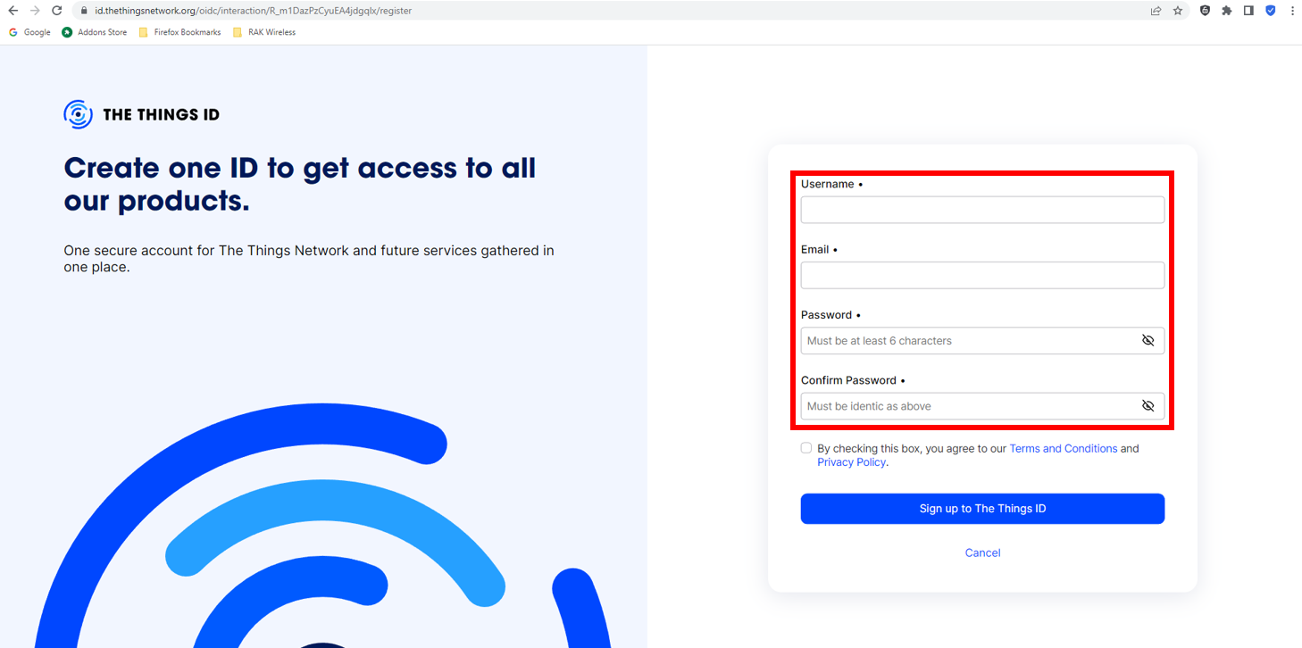 Figure 1: Creation of an account through the Things ID
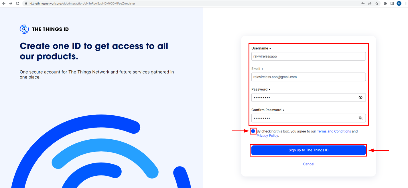 Figure 1: Creation of an account through the Things ID
You can use the same login credentials on the TTN V2 if you have one. If you have no account yet, you need to create one.
- Now that you are logged in to the platform, the next step is to create an application. Click Create an application.
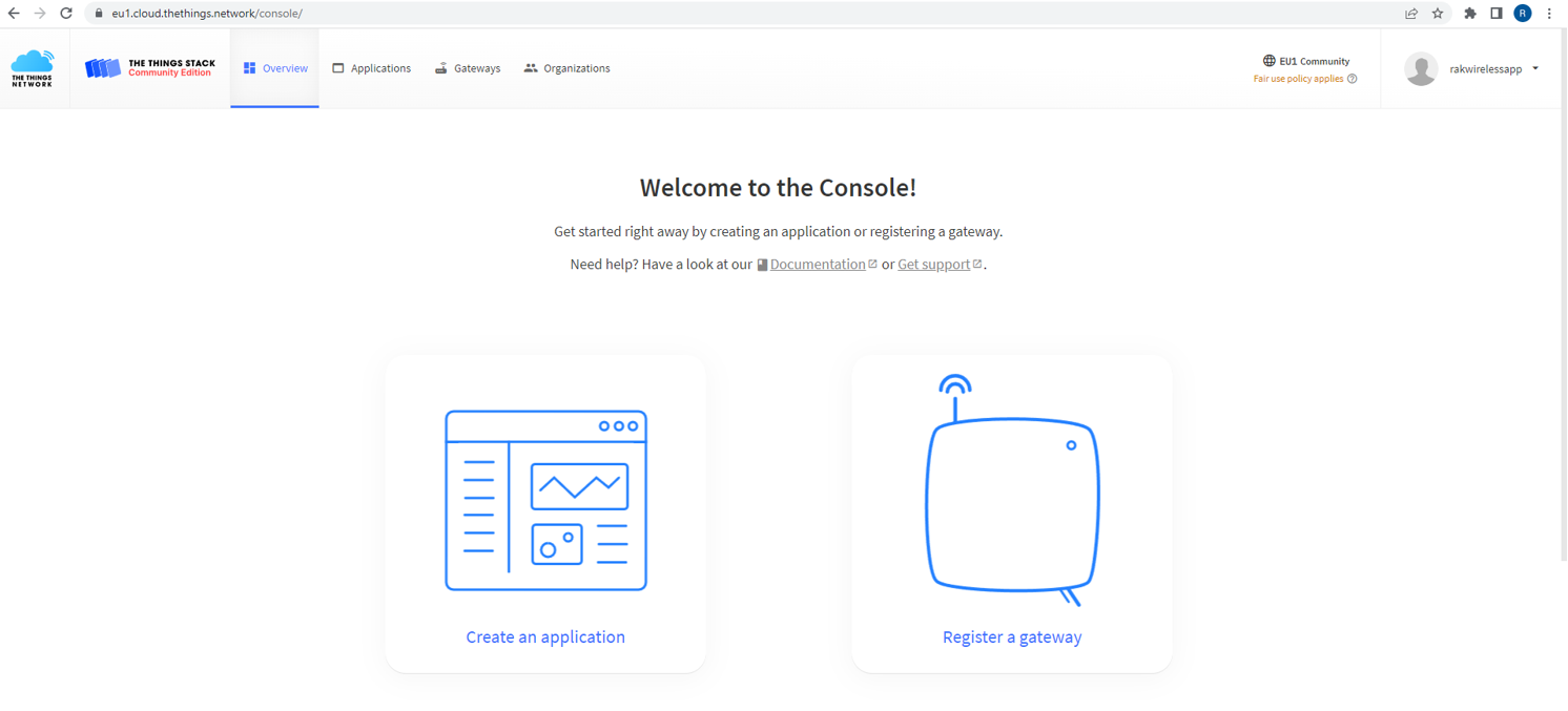 Figure 1: The Things Stack Platform
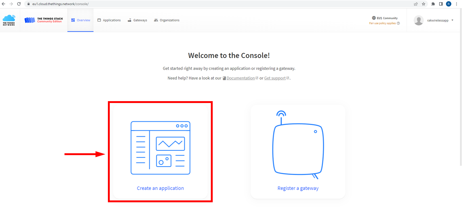 Figure 1: Creating TTN Application of your LoRaWAN devices
- To have an application registered, input first the specific details and necessary information about your application then click the Create application button.
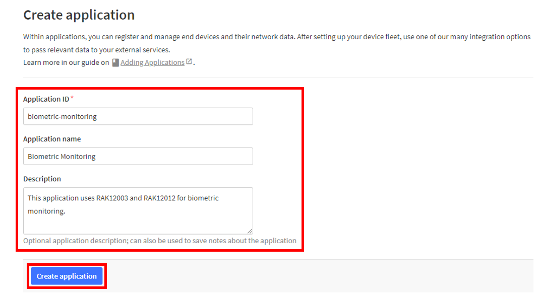 Figure 1: Details of the TTN application
The details and information are dependent to what device you are using (for example, RAK12012).
- If errors didn't occur in the previous step, you should now be on the application console page.
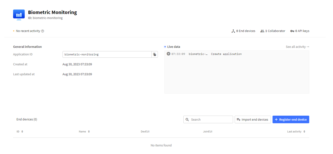 Figure 1: Biometric Monitoring Application Console
- Once done with the TTN account creation, you may now proceed with the device registration.
Biometric Monitoring - Device Registration
- Go to your application console to register a device. To start adding an OTAA end-device, click + Register end device, as shown below.
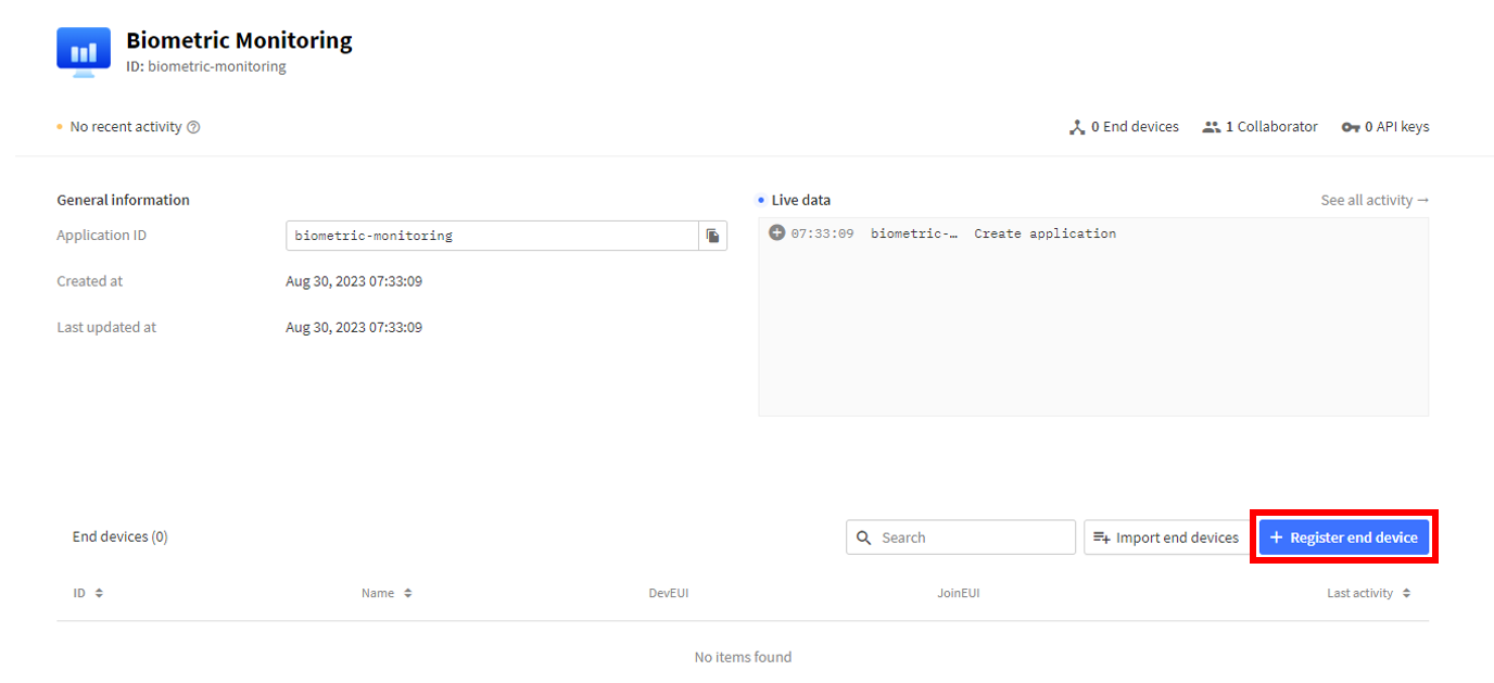 Figure 1: Register End Device
- To register the board, click Enter end device specifics manually.
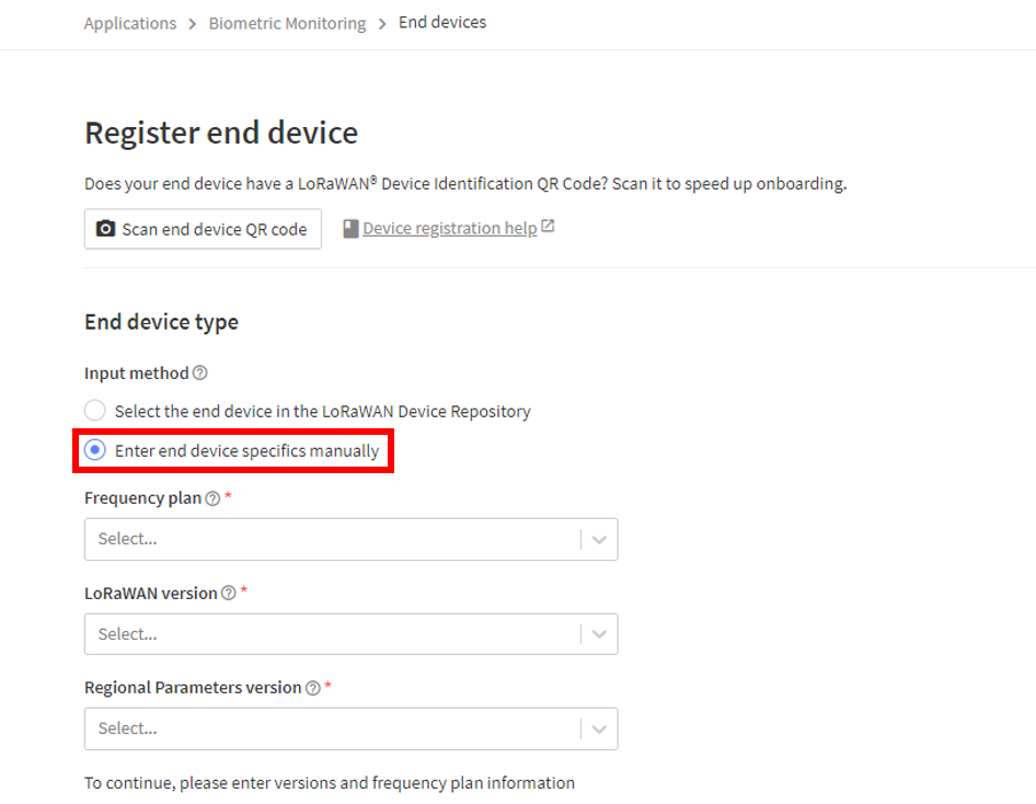 Figure 1: Enter end device specifics manually
- Next step is to set up Frequency plan, compatible LoRaWAN version, and Regional Parameters version supported. Then provide the JoinEUI credentials by entering zeroes into it.
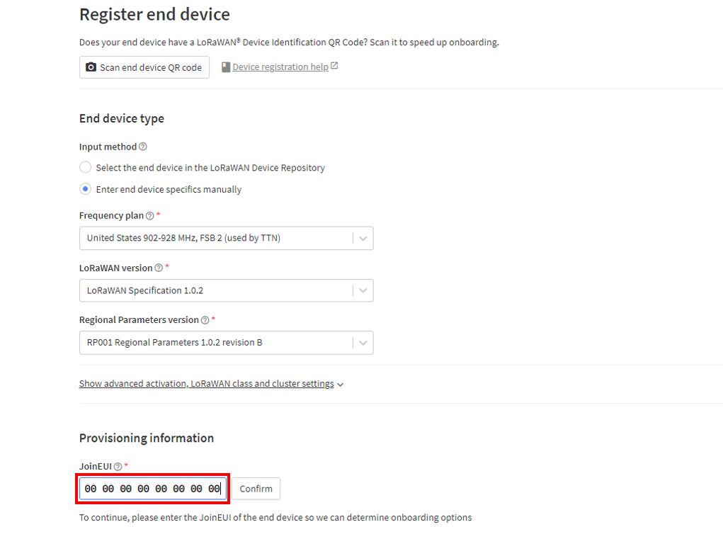 Figure 1: Setting up your device
-
Click Show advanced activation, LoRaWAN class and cluster settings, and then configure the following settings:
- Activation mode: Over the air activation (OTAA)
- Additional LoRaWAN class capabilities: None (class A only)
- Network defaults: Use network's default MAC settings
Under Provisioning information, click Confirm.
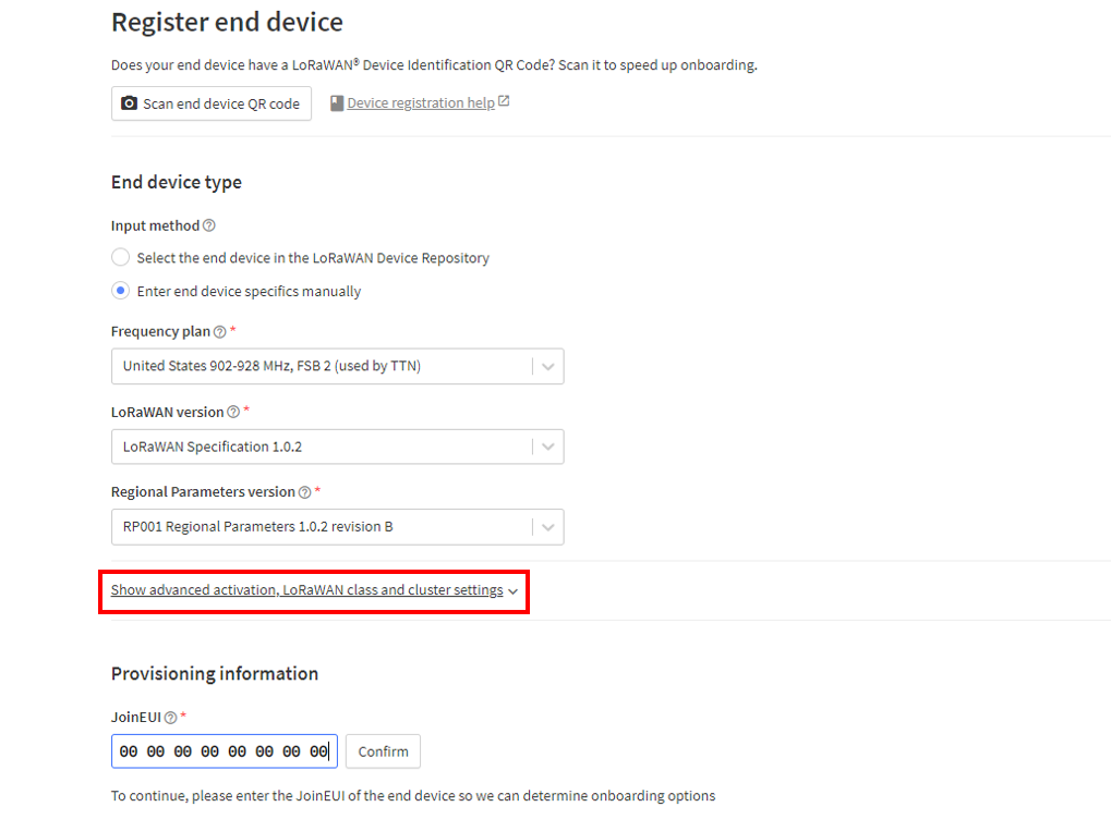 Figure 1: Setting up your device
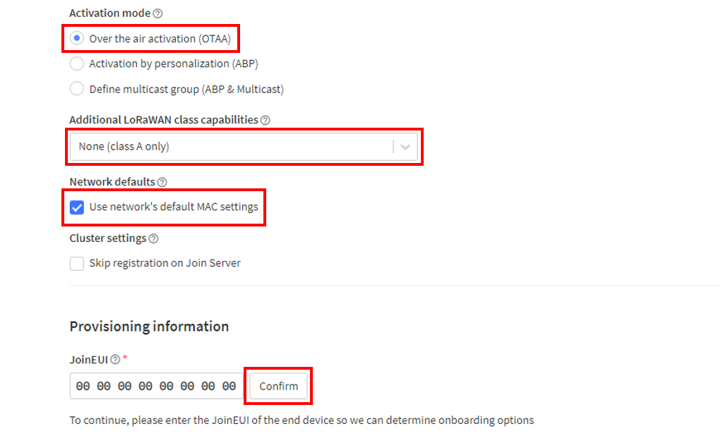 Figure 1: Setting up your device
- Once done, execute the following steps to register an end-device:
- Provide the DevEUI credentials of your device in the DevEUI portion. It will automatically generate the specific end-device ID of the board.
- Under the AppKey field, click Generate.
- After that, change the End device ID, as it is automatically prefilled using the DevEUI of your device.
- Then, click the Register end device button.
- The AppEUI, DevEUI, and AppKey are hidden in this section as these parameters are unique to a specific device. The DevEUI credential is unique to every RAK4631 device. Also, you should generate your own AppEUI and AppKey credentials for your specific device and application.
- The AppEUI is the same as the JoinEUI.
- The details under End device ID are dependent on what device you are using (for example, biometric-monitoring).
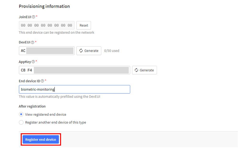 Figure 1: Register End Device
- You should now be able to see the device on the TTN console after you fully register your device, as shown below.
- To activate your LoRaWAN end-device via OTAA, you will need the AppEUI, DevEUI, and AppKey parameters. The AppKey is hidden by default for security reasons but is easily viewable by clicking the show button. You can also quickly copy the parameters by clicking the copy button.
- These parameters are always accessible on the device console page.
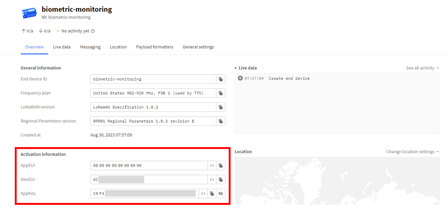 Figure 1: OTAA device successfully registered to TTN
- After creating the application and adding the device in TTN, you can proceed on the LoRaWAN Code uploading steps.
LoRaWAN Code for Biometric Monitoring
-
If you already have Arduino IDE installed on your laptop or PC and added RAK4631 board into it, you may proceed to the next step. If not, refer to the following section: Arduino IDE Installation.
-
After installing the Arduino IDE, you can start programming your Biometric Monitoring device. Copy and paste the code for the Biometric Monitoring LoRaWAN Application into the Arduino IDE.
The example code uses the SX126x-Arduino library, which must be installed for the LoRaWAN code to compile successfully.
#include <Arduino.h>
#include <LoRaWan-RAK4630.h>  //http://librarymanager/All#SX126x
#include <Wire.h>

#include "SparkFun_MLX90632_Arduino_Library.h"   // Click here to get the library: http://librarymanager/AllSparkFun_MLX90632_Arduino_Library
#include "MAX30105.h"                            // Click here to get the library: http://librarymanager/All#Sparkfun_3010x
#include "spo2_algorithm.h"
#define MLX90632_ADDRESS 0x3A
#define MAX_BRIGHTNESS 255

MLX90632 RAK_TempSensor;
MAX30105 particleSensor;

float object_temp = 0;
float sensor_temp = 0;

uint32_t irBuffer[100];       //infrared LED sensor data
uint32_t redBuffer[100];      //red LED sensor data

int32_t bufferLength;         //data length
int32_t spo2;                 //SPO2 value
int8_t validSPO2;             //indicator to show if the SPO2 calculation is valid
int32_t heartRate;            //heart rate value
int8_t validHeartRate;        //indicator to show if the heart rate calculation is valid

byte pulseLED = LED_GREEN;    //Must be on PWM pin
byte readLED = LED_BLUE;      //Blinks with each data read

#ifdef RAK4630
#define BOARD "RAK4631 "
#define RAK4631_BOARD true
#else
#define RAK4631_BOARD false
#endif

bool doOTAA = true;                                               // OTAA is used by default.
#define SCHED_MAX_EVENT_DATA_SIZE APP_TIMER_SCHED_EVENT_DATA_SIZE /**< Maximum size of scheduler events. */
#define SCHED_QUEUE_SIZE 60                                       /**< Maximum number of events in the scheduler queue. */
#define LORAWAN_DATERATE DR_0                                     /*LoRaMac datarates definition, from DR_0 to DR_5*/
#define LORAWAN_TX_POWER TX_POWER_5                               /*LoRaMac tx power definition, from TX_POWER_0 to TX_POWER_15*/
#define JOINREQ_NBTRIALS 3                                        /**< Number of trials for the join request. */
DeviceClass_t g_CurrentClass = CLASS_A;                           /* class definition*/
LoRaMacRegion_t g_CurrentRegion = LORAMAC_REGION_US915;           /* Region:EU868*/
lmh_confirm g_CurrentConfirm = LMH_CONFIRMED_MSG;                 /* confirm/unconfirm packet definition*/
uint8_t gAppPort = LORAWAN_APP_PORT;                              /* data port*/

/**@brief Structure containing LoRaWan parameters, needed for lmh_init()
*/
static lmh_param_t g_lora_param_init = { LORAWAN_ADR_ON, LORAWAN_DATERATE, LORAWAN_PUBLIC_NETWORK, JOINREQ_NBTRIALS, LORAWAN_TX_POWER, LORAWAN_DUTYCYCLE_OFF };

// Forward declaration
static void lorawan_has_joined_handler(void);
static void lorawan_join_failed_handler(void);
static void lorawan_rx_handler(lmh_app_data_t *app_data);
static void lorawan_confirm_class_handler(DeviceClass_t Class);
static void send_lora_frame(void);

/**@brief Structure containing LoRaWan callback functions, needed for lmh_init()
*/
static lmh_callback_t g_lora_callbacks = { BoardGetBatteryLevel, BoardGetUniqueId, BoardGetRandomSeed,
                                           lorawan_rx_handler, lorawan_has_joined_handler, lorawan_confirm_class_handler, lorawan_join_failed_handler };
//OTAA keys !!!! KEYS ARE MSB !!!!
uint8_t nodeDeviceEUI[8] = { 0xAC, 0x1F, 0x09, 0xFF, 0xFE, 0x05, 0x3E, 0x3E };
uint8_t nodeAppEUI[8] = { 0x00, 0x00, 0x00, 0x00, 0x00, 0x00, 0x00, 0x00 };
uint8_t nodeAppKey[16] = { 0xC8, 0xF4, 0x15, 0xF5, 0x20, 0x1D, 0x04, 0xD5, 0xF9, 0x89, 0x09, 0x13, 0xD3, 0x2D, 0xD0, 0x01 };

// ABP keys
uint32_t nodeDevAddr = 0x260116F8;
uint8_t nodeNwsKey[16] = { 0x7E, 0xAC, 0xE2, 0x55, 0xB8, 0xA5, 0xE2, 0x69, 0x91, 0x51, 0x96, 0x06, 0x47, 0x56, 0x9D, 0x23 };
uint8_t nodeAppsKey[16] = { 0xFB, 0xAC, 0xB6, 0x47, 0xF3, 0x58, 0x45, 0xC7, 0x50, 0x7D, 0xBF, 0x16, 0x8B, 0xA8, 0xC1, 0x7C };

// Private definition
#define LORAWAN_APP_DATA_BUFF_SIZE 64                                            /**< buffer size of the data to be transmitted. */
static uint8_t m_lora_app_data_buffer[LORAWAN_APP_DATA_BUFF_SIZE];               //< Lora user application data buffer.
static lmh_app_data_t m_lora_app_data = { m_lora_app_data_buffer, 0, 0, 0, 0 };  //< Lora user application data structure.

static uint32_t count = 0;
static uint32_t count_fail = 0;

void setup() {

  TwoWire &wirePort = Wire;
  MLX90632::status returnError;

  // Initialize LoRa chip.
  lora_rak4630_init();

  // Initialize Serial for debug output
  time_t timeout = millis();
  Serial.begin(115200);
  while (!Serial) {
    if ((millis() - timeout) < 5000) {
      delay(100);
    } else {
      break;
    }
  }
  Serial.println("=====================================");
  Serial.println("Welcome to RAK4630 LoRaWan!!!");
  if (doOTAA) {
    Serial.println("Type: OTAA");
  } else {
    Serial.println("Type: ABP");
  }

  switch (g_CurrentRegion) {
    case LORAMAC_REGION_AS923:
      Serial.println("Region: AS923");
      break;
    case LORAMAC_REGION_AU915:
      Serial.println("Region: AU915");
      break;
    case LORAMAC_REGION_CN470:
      Serial.println("Region: CN470");
      break;
    case LORAMAC_REGION_EU433:
      Serial.println("Region: EU433");
      break;
    case LORAMAC_REGION_IN865:
      Serial.println("Region: IN865");
      break;
    case LORAMAC_REGION_EU868:
      Serial.println("Region: EU868");
      break;
    case LORAMAC_REGION_KR920:
      Serial.println("Region: KR920");
      break;
    case LORAMAC_REGION_US915:
      Serial.println("Region: US915");
      break;
  }
  Serial.println("=====================================");

  // Setup the EUIs and Keys
  if (doOTAA) {
    lmh_setDevEui(nodeDeviceEUI);
    lmh_setAppEui(nodeAppEUI);
    lmh_setAppKey(nodeAppKey);
  } else {
    lmh_setNwkSKey(nodeNwsKey);
    lmh_setAppSKey(nodeAppsKey);
    lmh_setDevAddr(nodeDevAddr);
  }

  uint32_t err_code;
  // Initialize LoRaWan
  err_code = lmh_init(&g_lora_callbacks, g_lora_param_init, doOTAA, g_CurrentClass, g_CurrentRegion);
  if (err_code != 0) {
    Serial.printf("lmh_init failed - %d\n", err_code);
    return;
  }

  // Start Join procedure
  lmh_join();

  Serial.println("================================");
  Serial.println("RAK12012 + RAK12003 LoRaWAN Code");
  Serial.println("================================");

  Wire.begin(); //I2C init

  // RAK12003
  if (RAK_TempSensor.begin(MLX90632_ADDRESS, wirePort, returnError) == true) //MLX90632 init
  {
     Serial.println("MLX90632 Init Succeed");
  }
  else
  {
     Serial.println("MLX90632 Init Failed");
  }

  pinMode(pulseLED, OUTPUT);
  pinMode(readLED, OUTPUT);
  pinMode(WB_IO2, OUTPUT);
  digitalWrite(WB_IO2, HIGH);
  delay(300);

  // RAK12012
  if (!particleSensor.begin(Wire, I2C_SPEED_FAST)) //Use default I2C port, 400kHz speed
  {
    Serial.println(F("MAX30105 was not found. Please check wiring/power."));
    while (1);
  }
  particleSensor.setup(); //Configure sensor with default settings
}

void loop() {
  // Put your application tasks here, like reading of sensors,
  // Controlling actuators and/or other functions.

  bufferLength = 100; //buffer length of 100 stores 4 seconds of samples running at 25sps

  //read the first 100 samples, and determine the signal range
  for (byte i = 0 ; i < bufferLength ; i++)
  {
    while (particleSensor.available() == false) //do we have new data?
      particleSensor.check(); //Check the sensor for new data

    redBuffer[i] = particleSensor.getRed();
    irBuffer[i] = particleSensor.getIR();
    particleSensor.nextSample(); //We're finished with this sample so move to next sample
  }

  //calculate heart rate and SpO2 after first 100 samples (first 4 seconds of samples)
  maxim_heart_rate_and_oxygen_saturation(irBuffer, bufferLength, redBuffer, &spo2, &validSPO2, &heartRate, &validHeartRate);

  //Continuously taking samples from MAX30102.  Heart rate and SpO2 are calculated every 1 second
  while (1)
  {
    //dumping the first 25 sets of samples in the memory and shift the last 75 sets of samples to the top
    for (byte i = 25; i < 100; i++)
    {
      redBuffer[i - 25] = redBuffer[i];
      irBuffer[i - 25] = irBuffer[i];
    }

    //take 25 sets of samples before calculating the heart rate.
    for (byte i = 75; i < 100; i++)
    {
      while (particleSensor.available() == false) //do we have new data?
        particleSensor.check(); //Check the sensor for new data

      digitalWrite(readLED, !digitalRead(readLED)); //Blink onboard LED with every data read

      redBuffer[i] = particleSensor.getRed();
      irBuffer[i] = particleSensor.getIR();
      particleSensor.nextSample(); //We're finished with this sample so move to next sample

      //send samples and calculation result to terminal program through UART
      Serial.print(F(", HR="));
      Serial.print(heartRate, DEC);

      Serial.print(F(", SPO2="));
      Serial.print(spo2, DEC);

      Serial.println();
    }

    //After gathering 25 new samples recalculate HR and SP02
    maxim_heart_rate_and_oxygen_saturation(irBuffer, bufferLength, redBuffer, &spo2, &validSPO2, &heartRate, &validHeartRate);

    delay(5000);

    // RAK12003 Module
    object_temp = RAK_TempSensor.getObjectTemp();  // Get the temperature of the object we're looking at
    sensor_temp = RAK_TempSensor.getSensorTemp();   // Get the temperature of the sensor

    Serial.println("Sending frame now...");
    send_lora_frame();

    Serial.print("Object temperature: ");
    Serial.print(object_temp, 2);
    Serial.print(" F");
    Serial.println();

    Serial.print("Sensor temperature: ");
    Serial.print(sensor_temp, 2);
    Serial.print(" C");
    Serial.println();
  }
}

/**@brief LoRa function for handling HasJoined event.
 */
void lorawan_has_joined_handler(void) {
  Serial.println("OTAA Mode, Network Joined!");
}

/**@brief LoRa function for handling OTAA join failed
*/
static void lorawan_join_failed_handler(void) {
  Serial.println("OTAA join failed!");
  Serial.println("Check your EUI's and Keys's!");
  Serial.println("Check if a Gateway is in range!");
}
/**@brief Function for handling LoRaWan received data from Gateway
 *
 * @param[in] app_data  Pointer to rx data
 */
void lorawan_rx_handler(lmh_app_data_t *app_data) {
  Serial.printf("LoRa Packet received on port %d, size:%d, rssi:%d, snr:%d, data:%s\n",
                app_data->port, app_data->buffsize, app_data->rssi, app_data->snr, app_data->buffer);
}

void lorawan_confirm_class_handler(DeviceClass_t Class) {
  Serial.printf("switch to class %c done\n", "ABC"[Class]);
  // Informs the server that switch has occurred ASAP
  m_lora_app_data.buffsize = 0;
  m_lora_app_data.port = gAppPort;
  lmh_send(&m_lora_app_data, g_CurrentConfirm);
}

String data = "";

void send_lora_frame(void) {
  if (lmh_join_status_get() != LMH_SET) {
    //Not joined, try again later
    return;
  }

  Serial.print("result: ");
  uint32_t i = 0;
  memset(m_lora_app_data.buffer, 0, LORAWAN_APP_DATA_BUFF_SIZE);
  m_lora_app_data.port = gAppPort;

  data = " SpO2: " + String(spo2) + " Heart_Rate: " + String(heartRate) + " Object_Temp: " + String(object_temp) + " F " + " Sensor_Temp: " + String(sensor_temp) + " C ";

  Serial.println(data);

  uint16_t object_temp_data = object_temp * 100;
  int32_t spo2_data = spo2;
  int32_t heartRate_data = heartRate;

  m_lora_app_data.buffer[i++] = 0x01;  // byte[0]

  // Data from RAK12012 module
  m_lora_app_data.buffer[i++] = (int8_t)((spo2_data & 0xFF000000) >> 24);       // byte[1]
  m_lora_app_data.buffer[i++] = (int8_t)((spo2_data & 0x00FF0000) >> 16);       // byte[2]
  m_lora_app_data.buffer[i++] = (int8_t)((spo2_data & 0x0000FF00) >> 8);        // byte[3]
  m_lora_app_data.buffer[i++] = (int8_t)(spo2_data & 0x000000FF);               // byte[4]

  // Data from RAK12012 module
  m_lora_app_data.buffer[i++] = (int8_t)((heartRate_data & 0xFF000000) >> 24);   // byte[5]
  m_lora_app_data.buffer[i++] = (int8_t)((heartRate_data & 0x00FF0000) >> 16);   // byte[6]
  m_lora_app_data.buffer[i++] = (int8_t)((heartRate_data & 0x0000FF00) >> 8);    // byte[7]
  m_lora_app_data.buffer[i++] = (int8_t)(heartRate_data & 0x000000FF);           // byte[8]

  // Data from RAK12003 module
  m_lora_app_data.buffer[i++] = (uint8_t)((object_temp_data & 0x0000FF00) >> 8); // byte[9]
  m_lora_app_data.buffer[i++] = (uint8_t)(object_temp_data & 0x000000FF);        // byte[10]

  m_lora_app_data.buffsize = i;

  lmh_error_status error = lmh_send(&m_lora_app_data, g_CurrentConfirm);
  if (error == LMH_SUCCESS) {
    count++;
    Serial.printf("lmh_send ok count %d\n", count);
  } else {
    count_fail++;
    Serial.printf("lmh_send fail count %d\n", count_fail);
  }
}
 Figure 1: OTAA device successfully registered to TTN
- Once done with the code, you can now proceed to upload it to your device. On your desktop or laptop, select the RAK4631 board. To do so, navigate to Tools > Board:XXXXX > RAKwireless nRF Boards > WisBlock RAK4631.
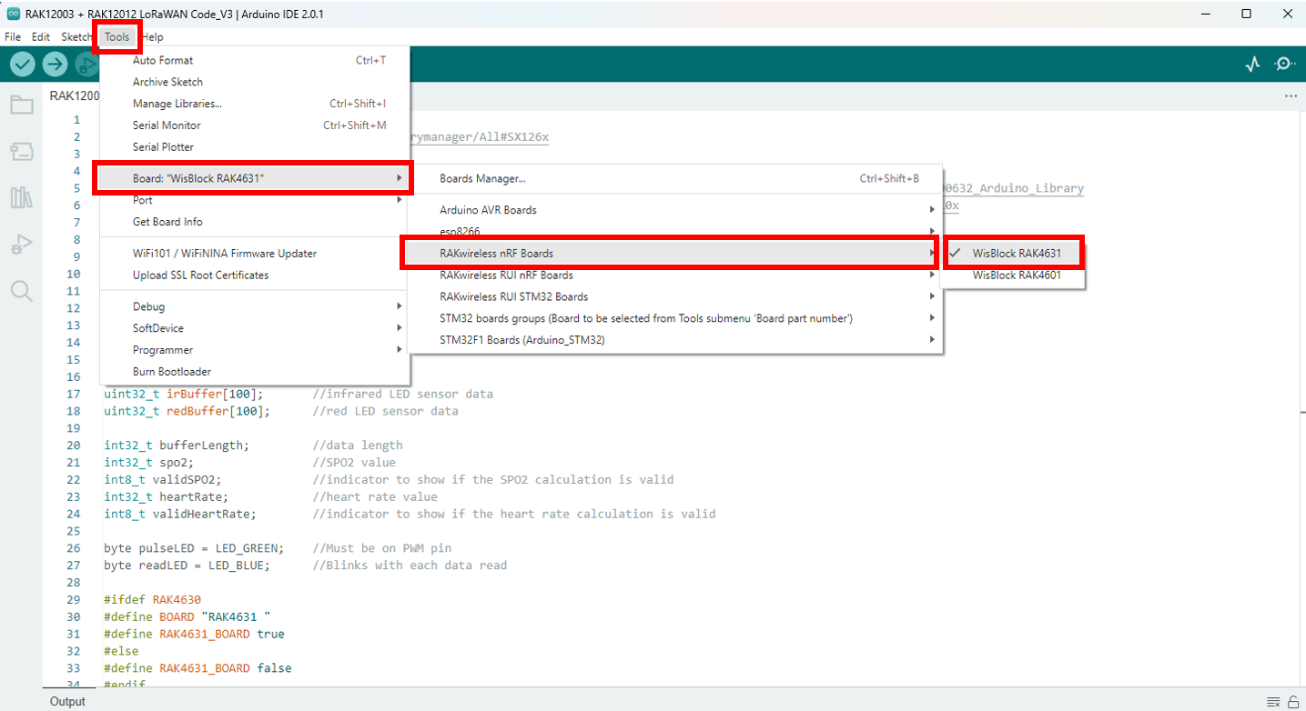 Figure 1: Selecting the RAK4631 board
- Following the selection of your board, you must specify the specific port of your board. To accomplish this, navigate to Tools > Port > then the specific port on your board.
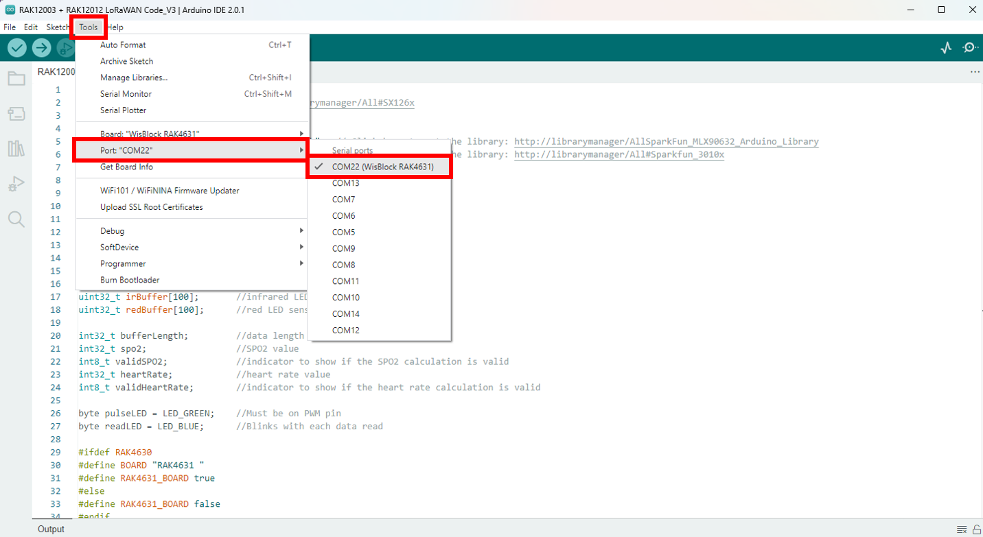 Figure 1: Selecting the port of RAK4631 board
- You can now upload your code. Simply click the right arrow sign in the upper left corner of your Arduino IDE. The Device programmed notification will appear at the bottom.
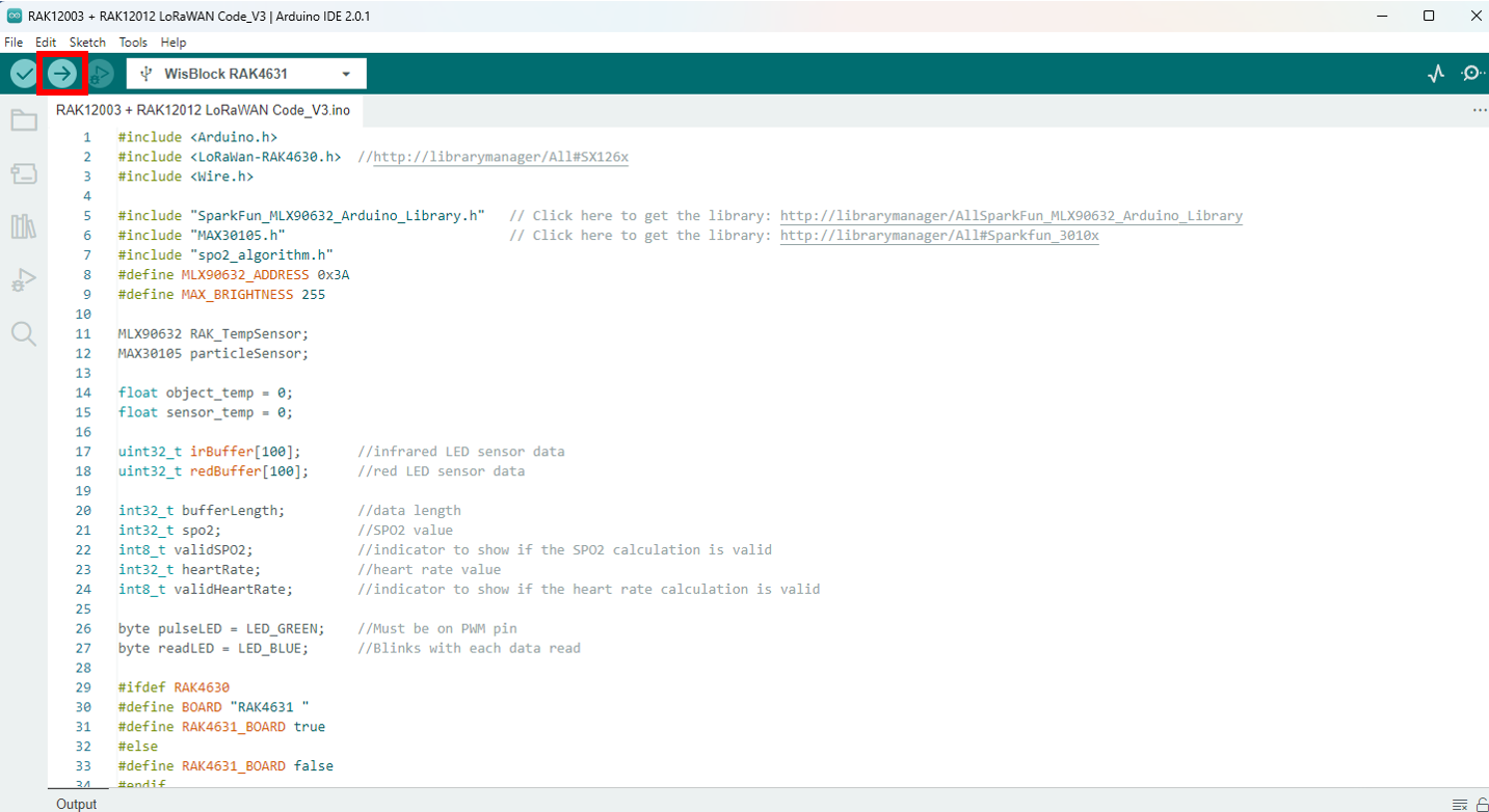 Figure 1: Uploading your code into your RAK4631 board
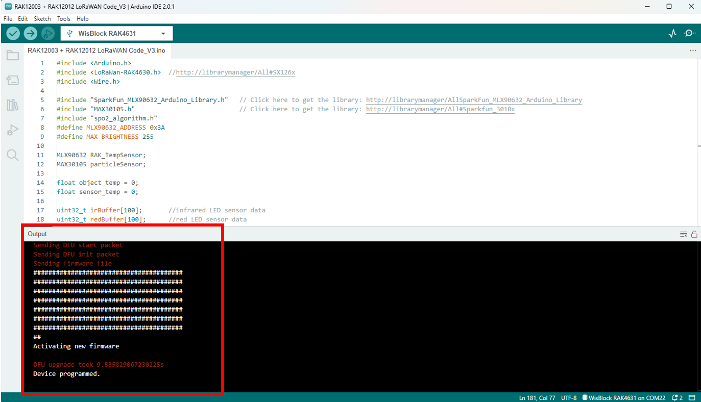 Figure 1: Arduino code is successfully uploaded into your RAK4631 board
Biometric Monitoring via TTN
- To monitor the data of your Biometric Monitoring device via TTN, you need to go back to your TTN account where you created your application and registered your device.
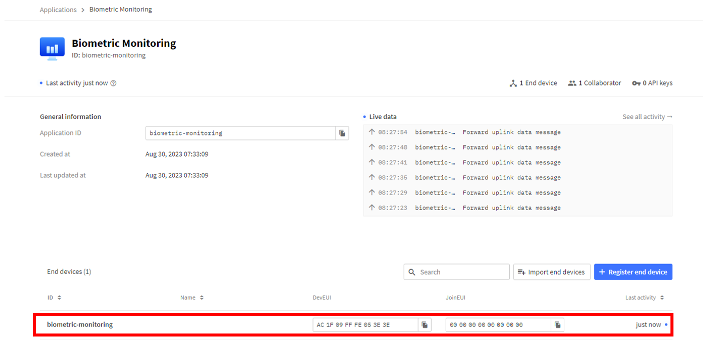 Figure 1: Biometric Monitoring device in TTN
- Navigate to Payload formatters > Formatter type > Custom Javascript formatter > Formatter code. Replace the default code to decode the data from your device going to TTN. Click Save changes.
// LoRaWAN code for RAK12012 + RAK12003 Application

function Decoder(bytes, port)
{

  var decoded = {};

  if (port === 2)
  {
    if( bytes[0] == 1) // check if the header byte is 1.
    {

      SpO2_data = (bytes[1] << 24) | (bytes[2] << 16) | (bytes[3] << 8) | (bytes[4]);
      Heart_Rate_data = (bytes[5] << 24) | (bytes[6] << 16) | (bytes[7] << 8) | (bytes[8]);
      sensor_temp_data = (bytes[9] << 8) | (bytes[10]);

      if((Heart_Rate_data < -1) || (Heart_Rate_data >= 201))
      {
        decoded.Heart_Rate = 0;
      }

      else
      {
        decoded.Heart_Rate = Heart_Rate_data;
      }

      if((SpO2_data < -1) || (SpO2_data >= 201))
      {
        decoded.SpO2 = 0;
      }

      else
      {
        decoded.SpO2 = SpO2_data;
      }

      decoded.sensor_temp_C = sensor_temp_data / 100;

      return decoded;
    }
  }
}
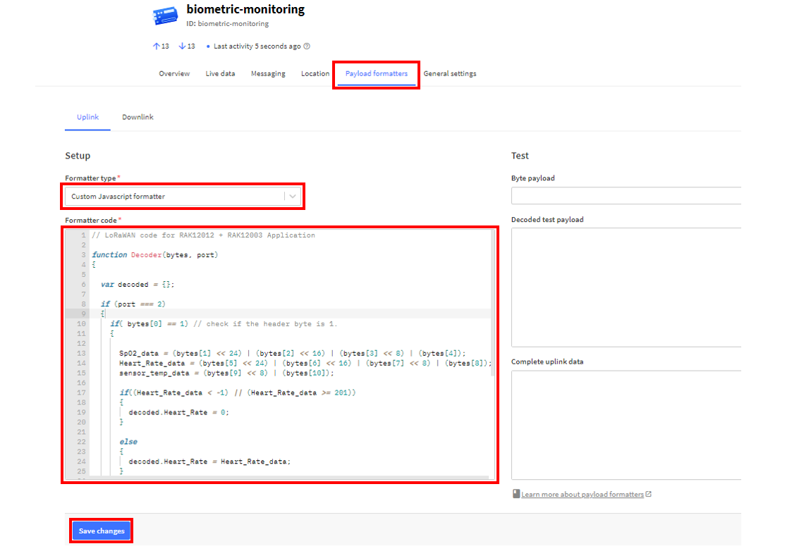 Figure 1: Payload Formatter
- Then go back to the Live data of your device in TTN. You should now be seeing results from it.
 Figure 1: Live data from your device in TTN
Biometric Monitoring via qubitro
This section will guide you on how to integrate your application using qubitro.
- Go to qubitro Portal and create your account.
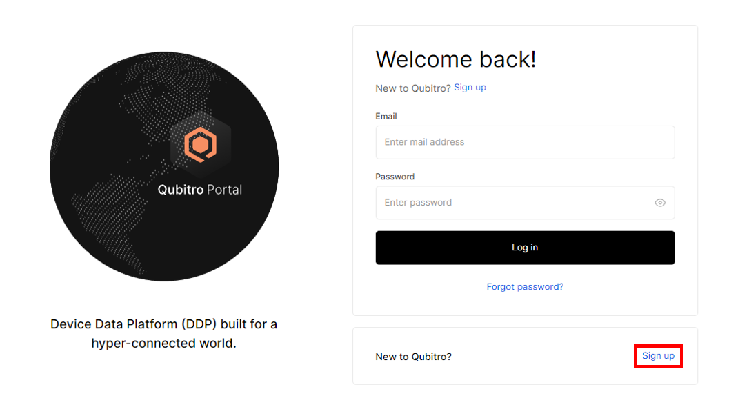 Figure 1: Creating qubitro Account
- Once done with the account creation, log in to your qubitro Account. Click New Project, type in your biometric monitoring application's Name and Description, and then click Create.
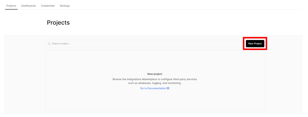 Figure 1: Creating New Project
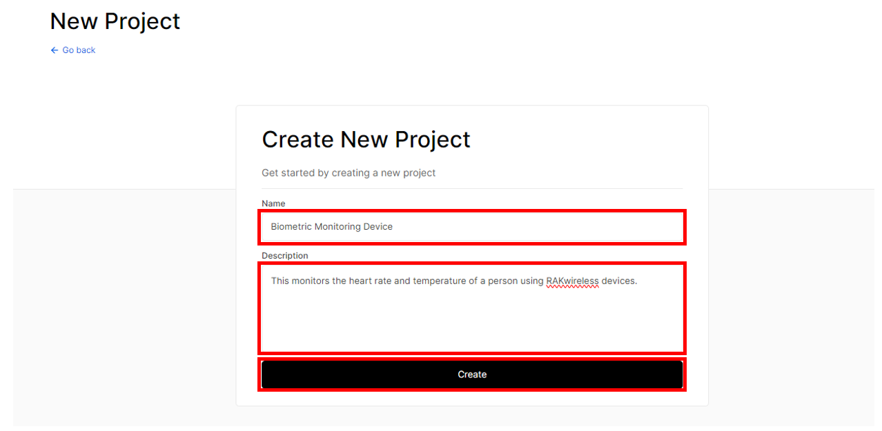 Figure 1: Creating New Project
 Figure 1: Creating New Project
- Head to your newly-created project, then click New source.
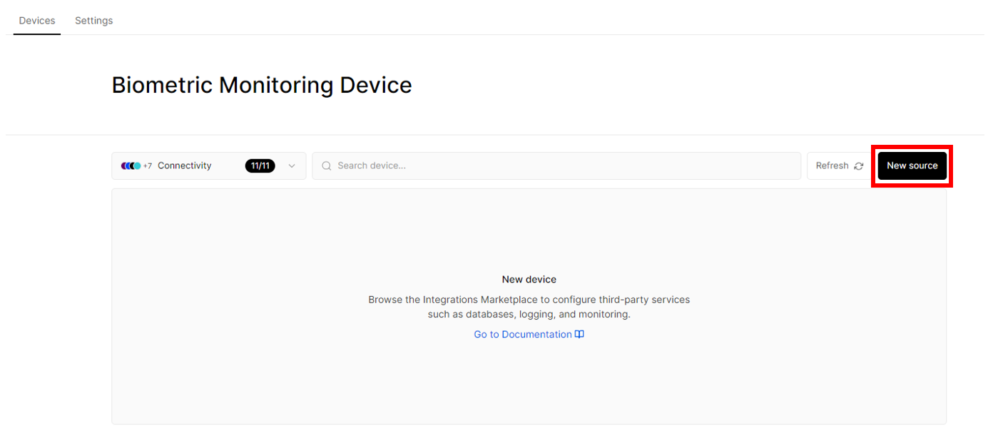 Figure 1: Adding New source
- Among the data sources, choose The Things Stack.
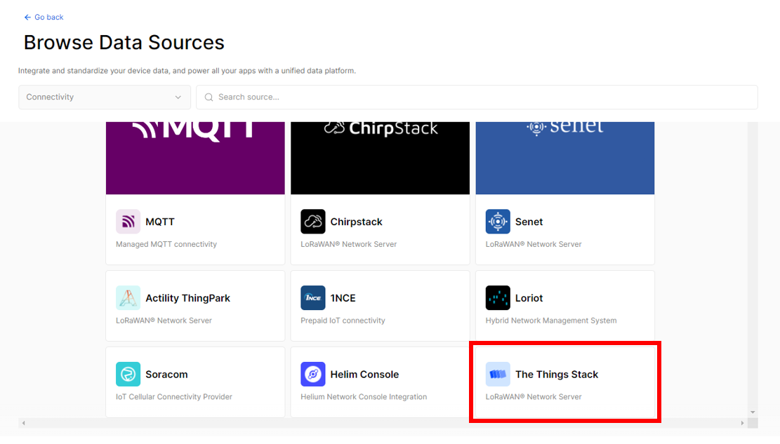 Figure 1: Choosing The Things Stack
- For the integration type, choose Import from network, then copy and paste the PROJECT ID and WEBHOOK SIGNING KEY temporarily to Notepad. These credentials will be needed later. Then click Go to project.
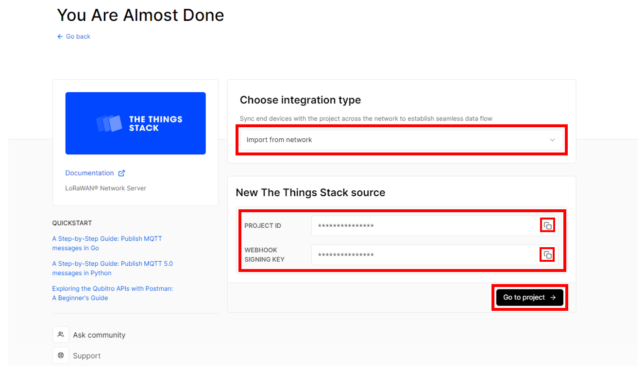 Figure 1: Copying the credentials
- Then head back to your TTN Application, where you created your biometric monitoring application to add a webhook. To do this, click on your device, then go to Integrations > Webhooks > + Add webhook.
 Figure 1: Going to your TTN application for your Biometric Monitoring Application
 Figure 1: Adding Webhook
- Choose qubitro as your webhook template.
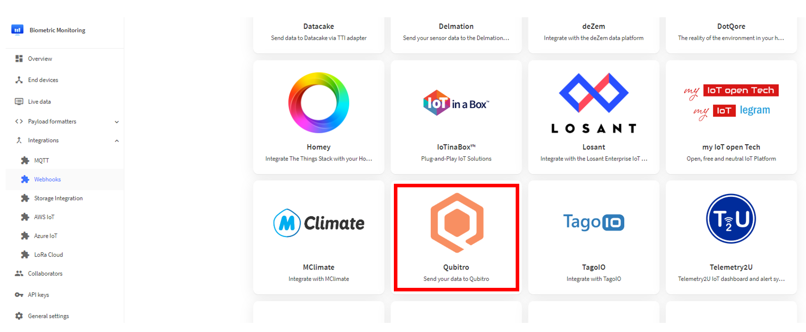 Figure 1: qubitro
- Fill in the needed details, then click Create qubitro webhook.
- Webhook ID - For this example, you can use biometric-monitoring-application.
- Project ID - Paste the credential you copied from Step 5.
- Webhook Signing Key - Paste the credential you copied from Step 5.
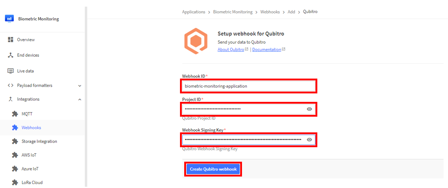 Figure 1: Creating qubitro webhook
 Figure 1: Added a qubitro webhook
- After creating your webhook, go back to your qubitro platform to check the changes made. Refresh qubitro by clicking the Refresh button in the upper right corner of your screen. The platform now includes a newly added device.
 Figure 1: Device successfully included in qubitro
- To add the decoder, go to Functions > Create Function. Then, under Decoder Function, click Get started. You will now redirect to Function Configuration.
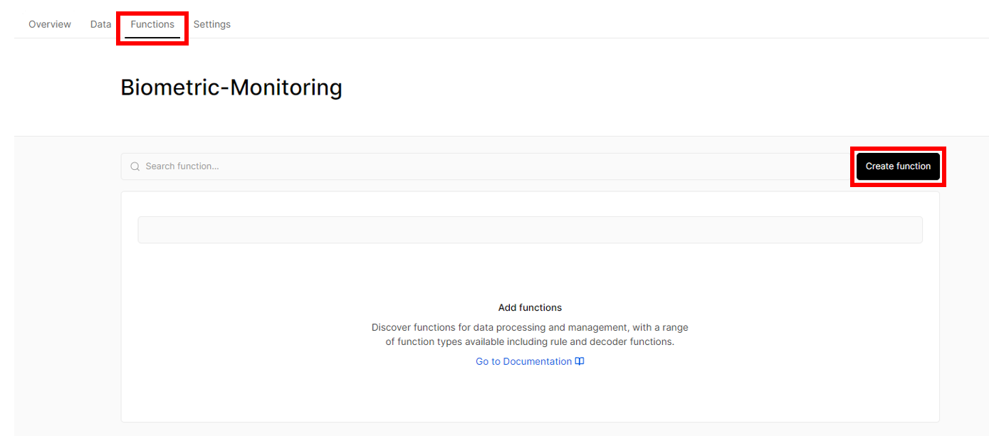 Figure 1: Creating Function
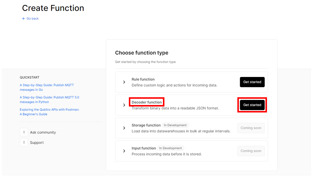 Figure 1: Decoder Function
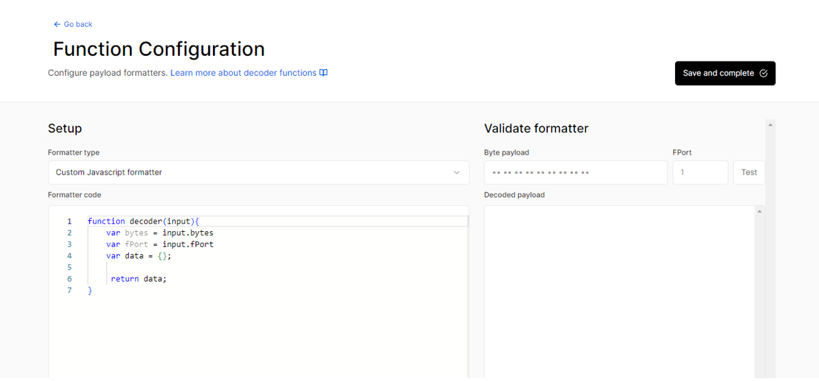 Figure 1: Function Configuration
- Under the Formatter type, choose Custom Javascript formatter. Then, under the Formatter code, you need to replace its default entry with the code below:
// LoRaWAN code for RAK12012 + RAK12003 Application

function Decoder(bytes, port)
{

  var decoded = {};

  if (port === 2)
  {
    if( bytes[0] == 1) // check if the header byte is 1.
    {

      SpO2_data = (bytes[1] << 24) | (bytes[2] << 16) | (bytes[3] << 8) | (bytes[4]);
      Heart_Rate_data = (bytes[5] << 24) | (bytes[6] << 16) | (bytes[7] << 8) | (bytes[8]);
      sensor_temp_data = (bytes[9] << 8) | (bytes[10]);

      if((Heart_Rate_data < -1) || (Heart_Rate_data >= 201))
      {
        decoded.Heart_Rate = 0;
      }

      else
      {
        decoded.Heart_Rate = Heart_Rate_data;
      }

      if((SpO2_data < -1) || (SpO2_data >= 201))
      {
        decoded.SpO2 = 0;
      }

      else
      {
        decoded.SpO2 = SpO2_data;
      }

      decoded.sensor_temp_C = sensor_temp_data / 100;

      return decoded;
    }
  }
}
- Once done, click Save and complete.
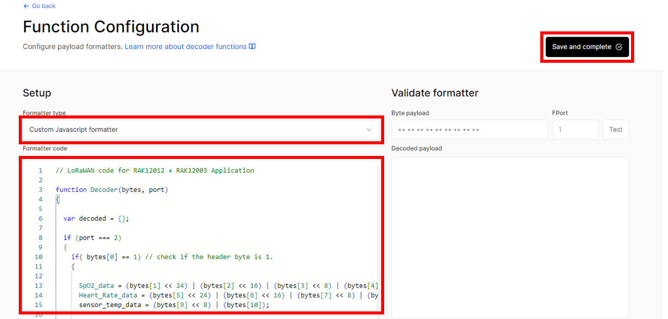 Figure 1: Function Configuration
 Figure 1: Created Decoder Function
- To check for the incoming data from your device, go to your device and click on the Data tab. You should now be seeing live data from your device. Click Refresh to gather the most recent data.
 Figure 1: Data Tab
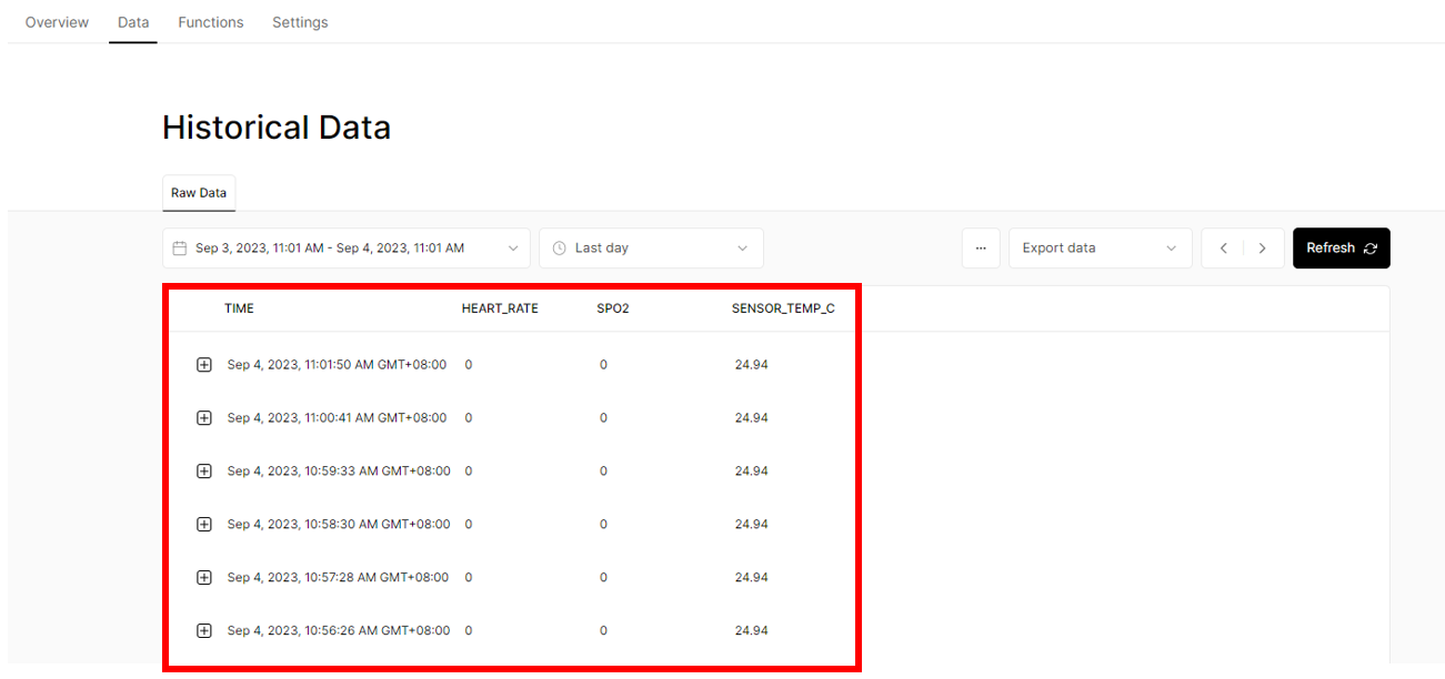 Figure 1: Historical Data
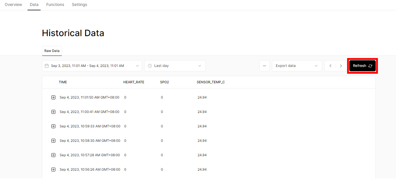 Figure 1: Refreshing data to get newer ones
- To add a monitoring dashboard for the data from the biometric monitoring device, you need to go to Home which is located at the left top most part of your screen.
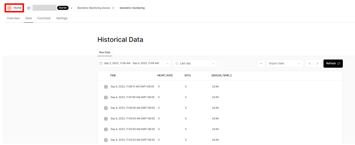 Figure 1: Creating dashboard for your Biometric Monitoring device
- Click Dashboards > New dashboard > Create new.
 Figure 1: Creating dashboard for your Biometric Monitoring device
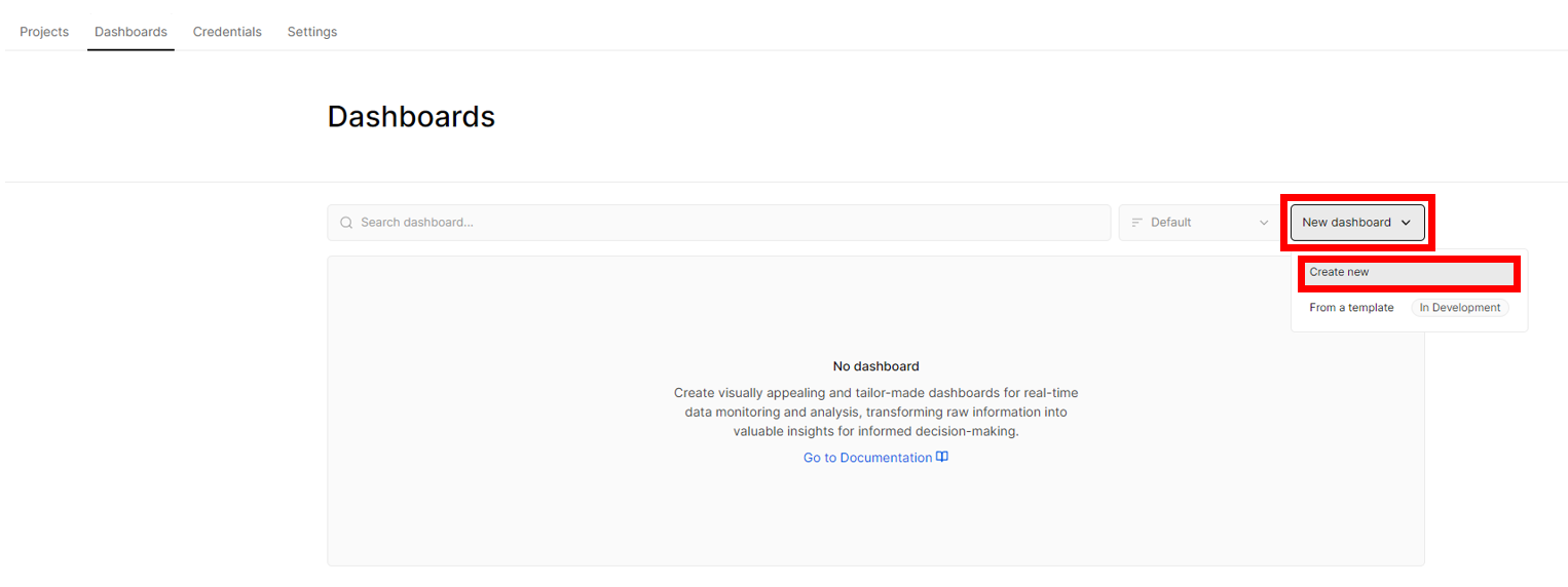 Figure 1: Creating dashboard for your Biometric Monitoring device
- Fill in the Create New Dashboard section using the details of your device. For the Tags, input Test, then click Create.
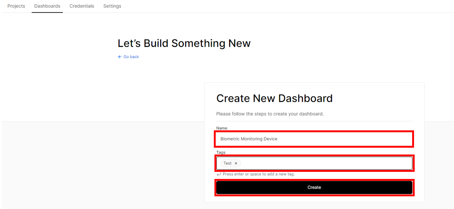 Figure 1: Creating dashboard for your Biometric Monitoring device
- Once done, click on to your newly-created dashboard.
 Figure 1: Newly-created dashboard for your Biometric Monitoring device
- To add a widget for a specific parameter that needs to be monitored, go to Edit > New widget.
 Figure 1: Adding a widget
 Figure 1: Adding a widget
- Once done, you're now at the Widget Configuration. At the WIDGET TYPE, choose Chart.
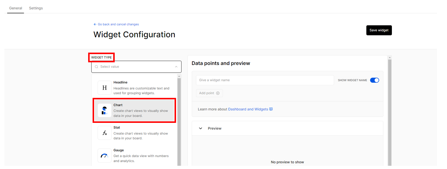 Figure 1: Widget Configuration
- Provide the parameter's name under SHOW WIDGET NAME, then click Add point +.
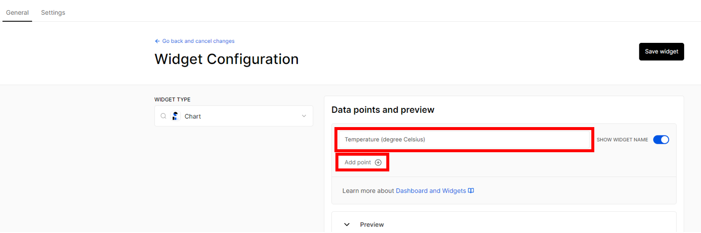 Figure 1: Widget Configuration
- A Connect Data Point window will appear. Choose your existing project, application and the specific parameter you need to monitor in your dashboard. Once done, click Save.
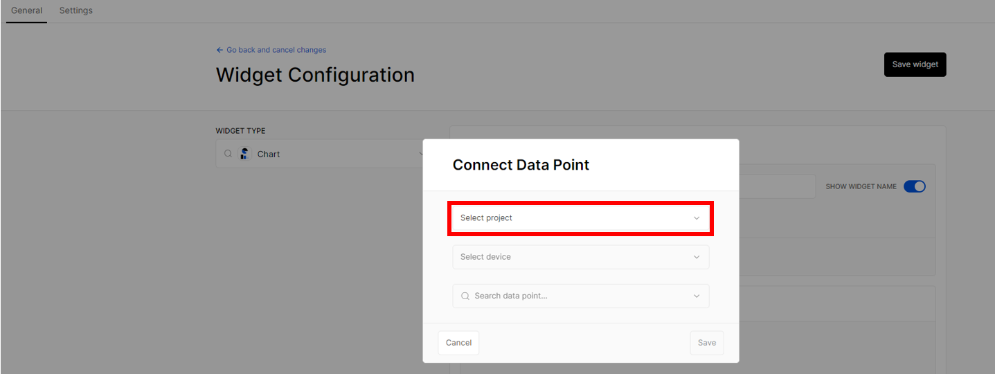 Figure 1: Project selection
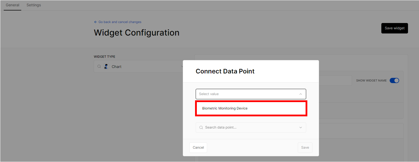 Figure 1: Selected project
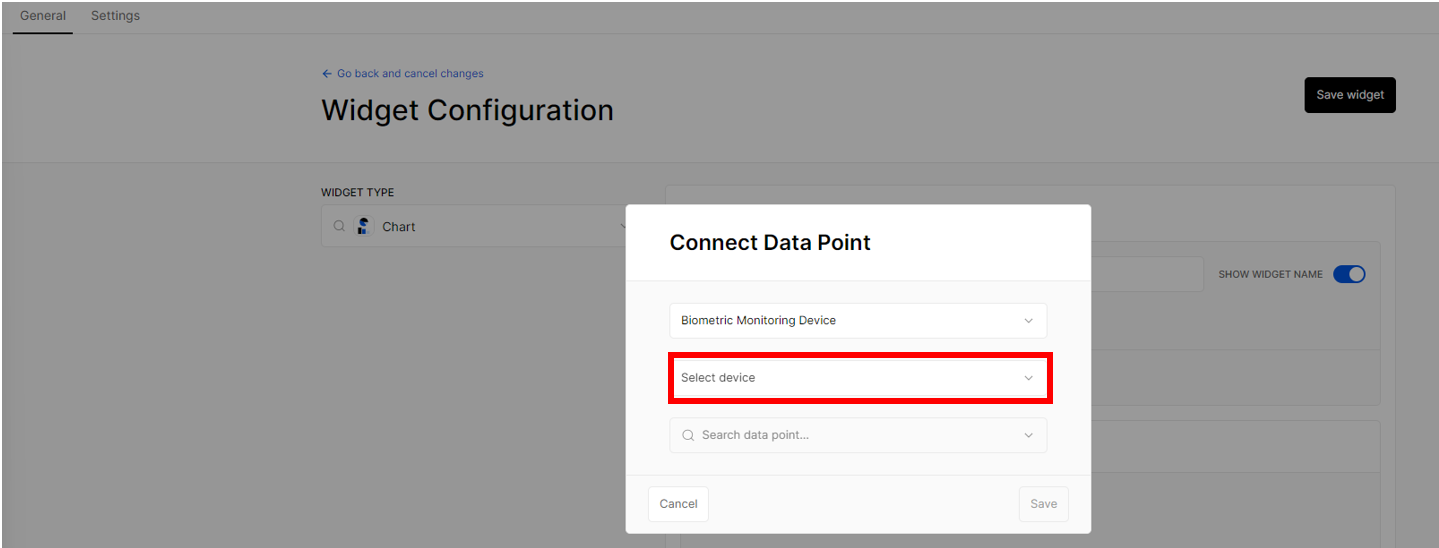 Figure 1: Device selection
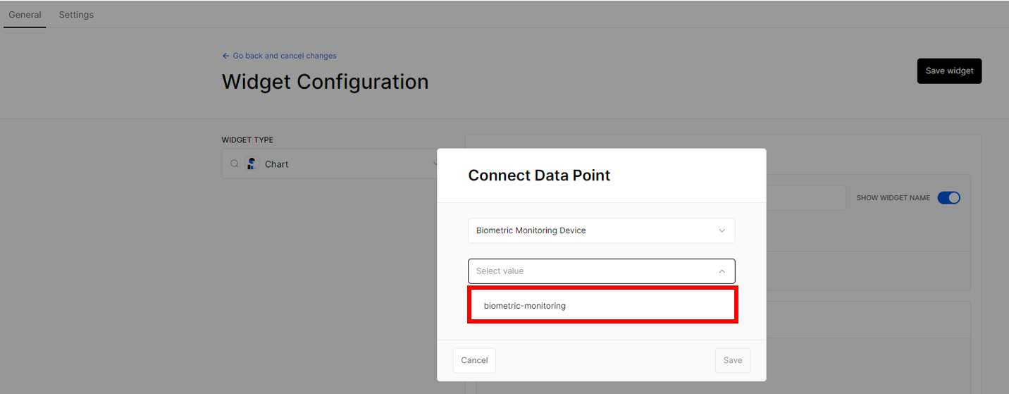 Figure 1: Selected a device
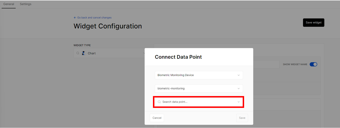 Figure 1: Data point selection
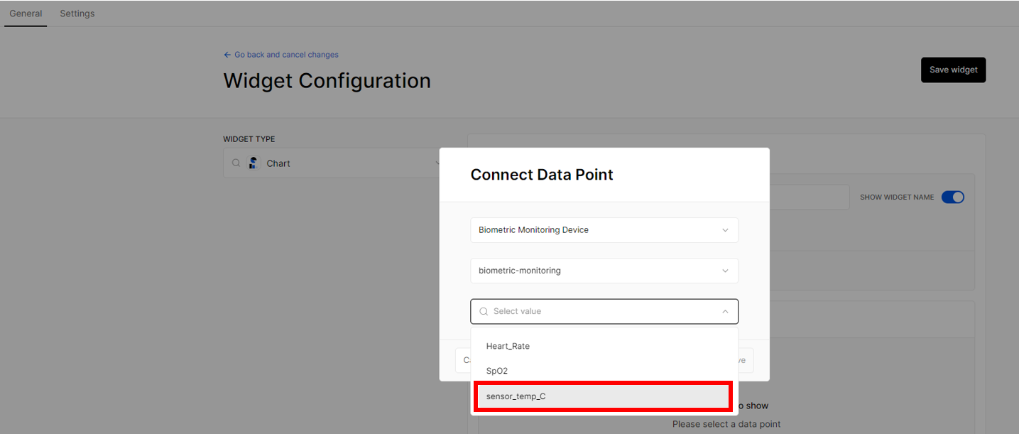 Figure 1: Selected data point
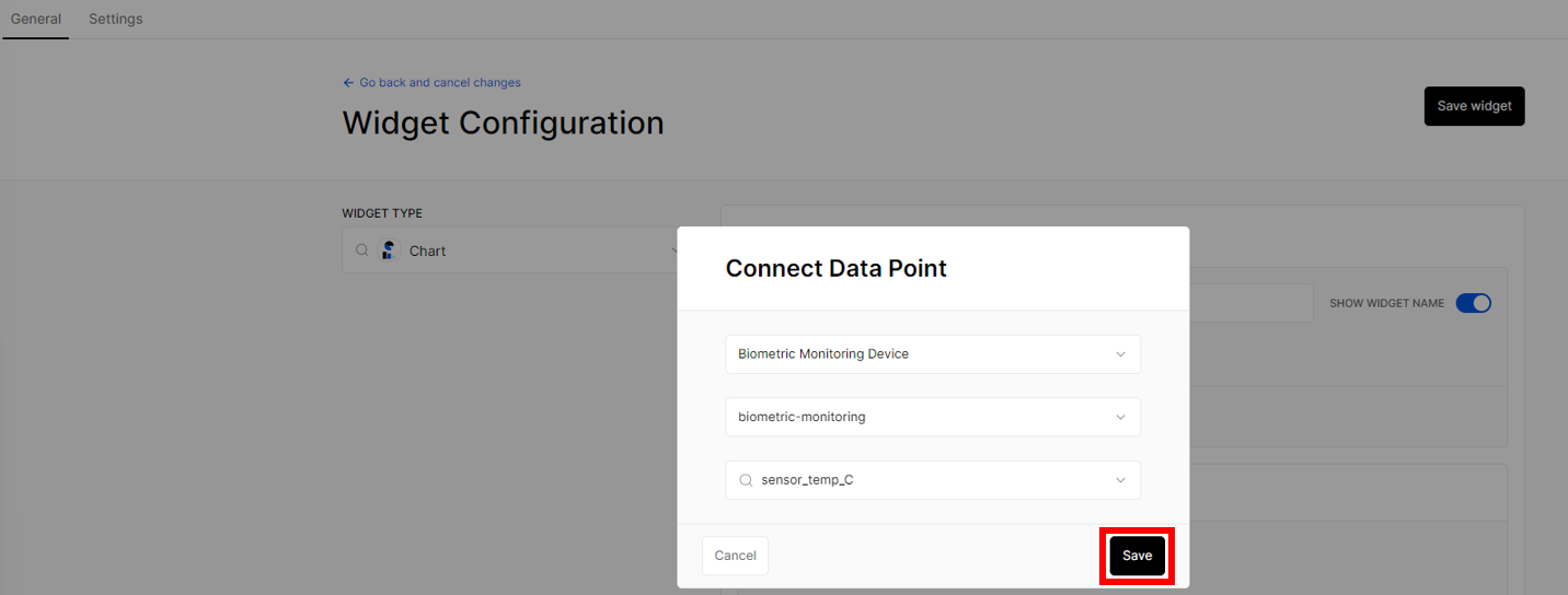 Figure 1: Save the data point
- Your device should already have a preview of your data. Under CHART TYPE on the left side of your screen, choose Line.
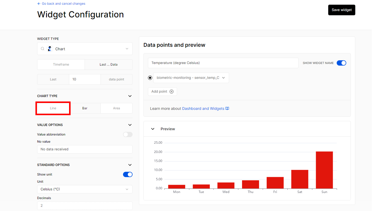 Figure 1: Widget Configuration
- After that, go to STANDARD OPTIONS and select the appropriate unit for the parameter you want to monitor in the dashboard. Once finished, click Save widget.
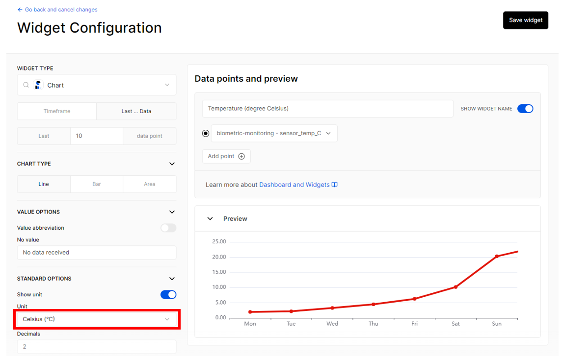 Figure 1: Saving the changes made in your Widget Configuration
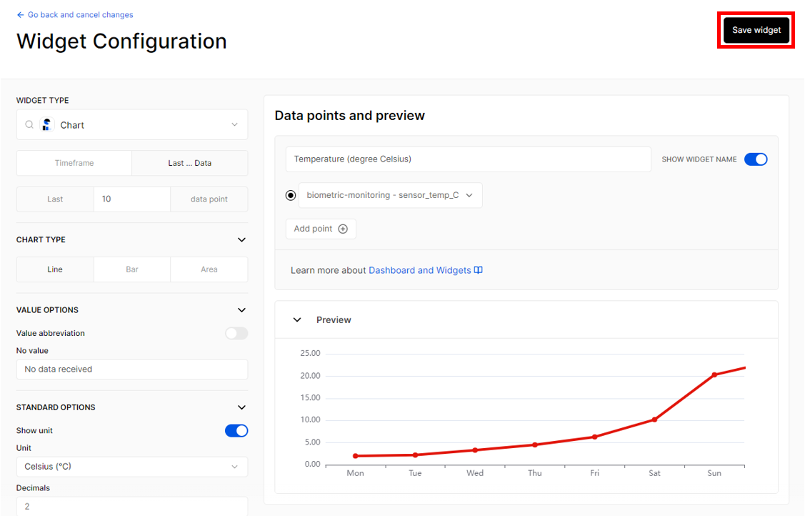 Figure 1: Data points line graph
- Click Save changes to include the parameter data. Then, you have the newly-made widget for your specific parameter.
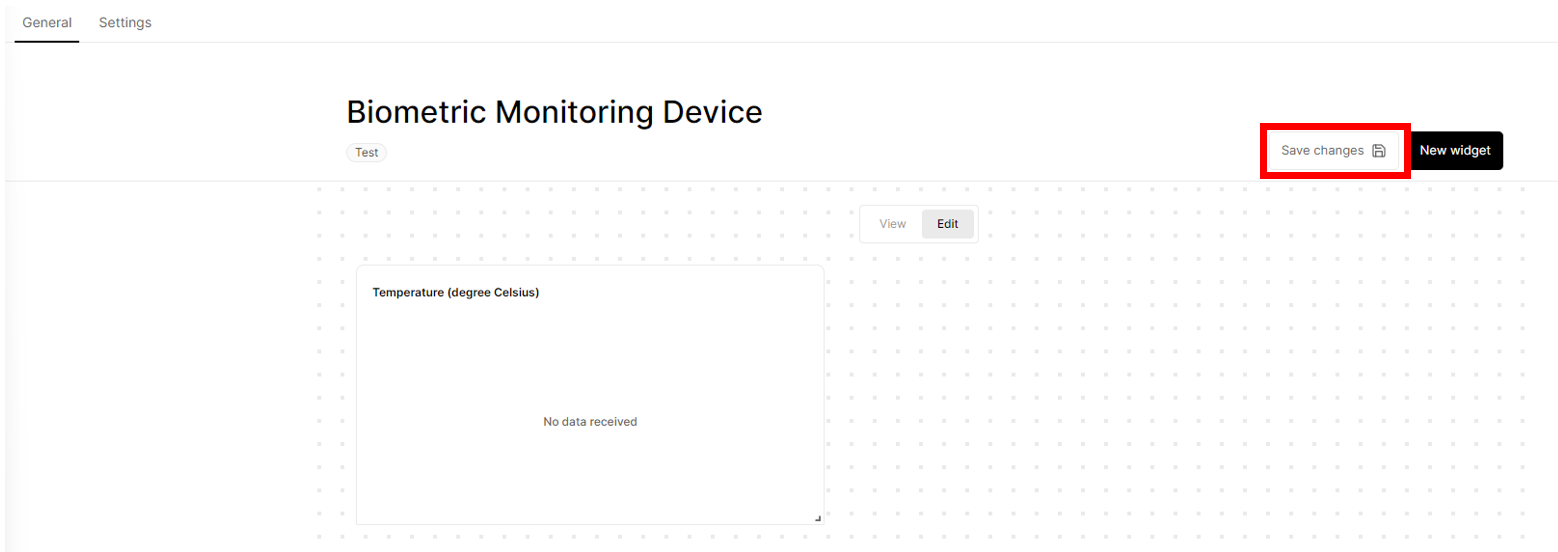 Figure 1: Save changes
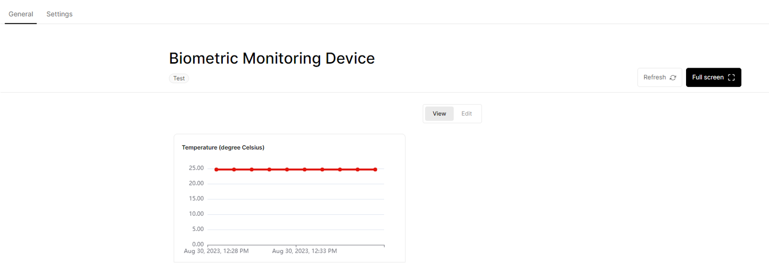 Figure 1: Newly-made widget
- Repeat from Step 18-24 to add another widgets for other parameters.
- You now have a real-time monitoring dashboard for your biometric monitoring device.
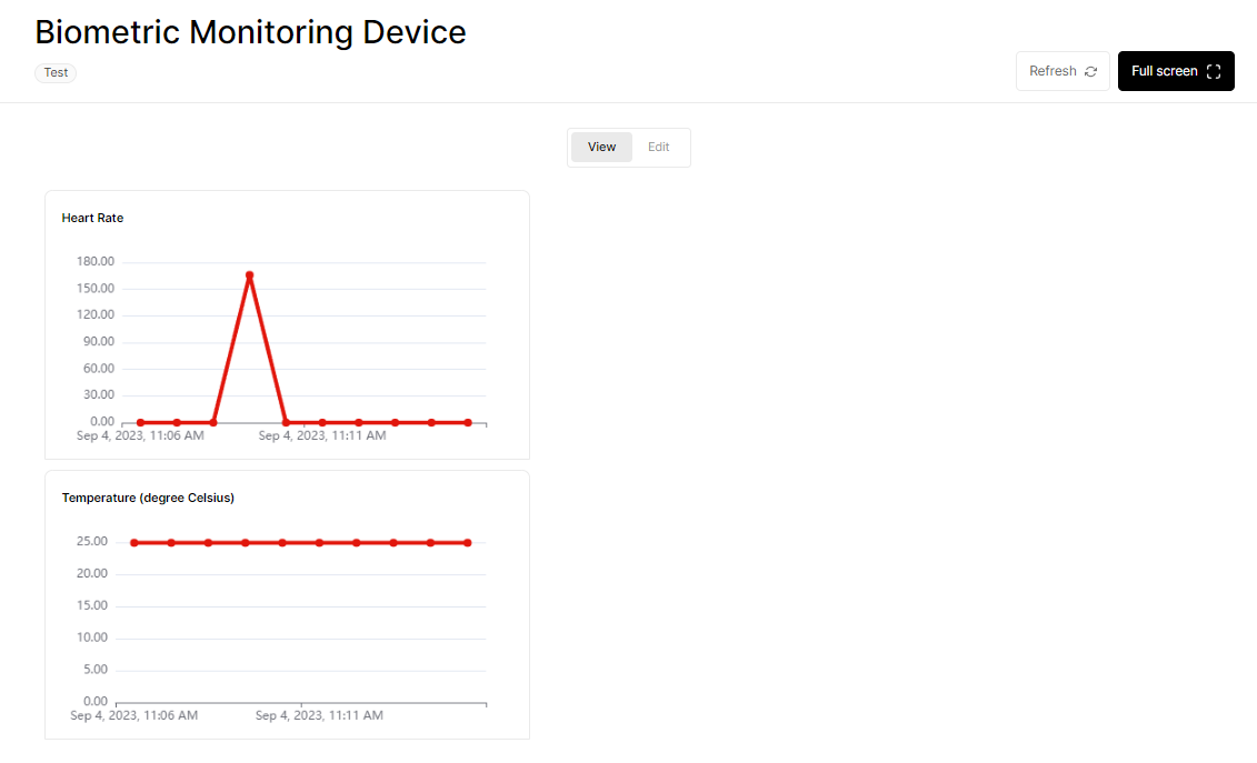 Figure 1: Monitoring dashboard for your biometric monitoring device
Miscellaneous
Arduino IDE Installation + RAK4631
- Download the Arduino IDE and install it on your PC or laptop. Choose the appropriate Arduino IDE, depending on your operating system.
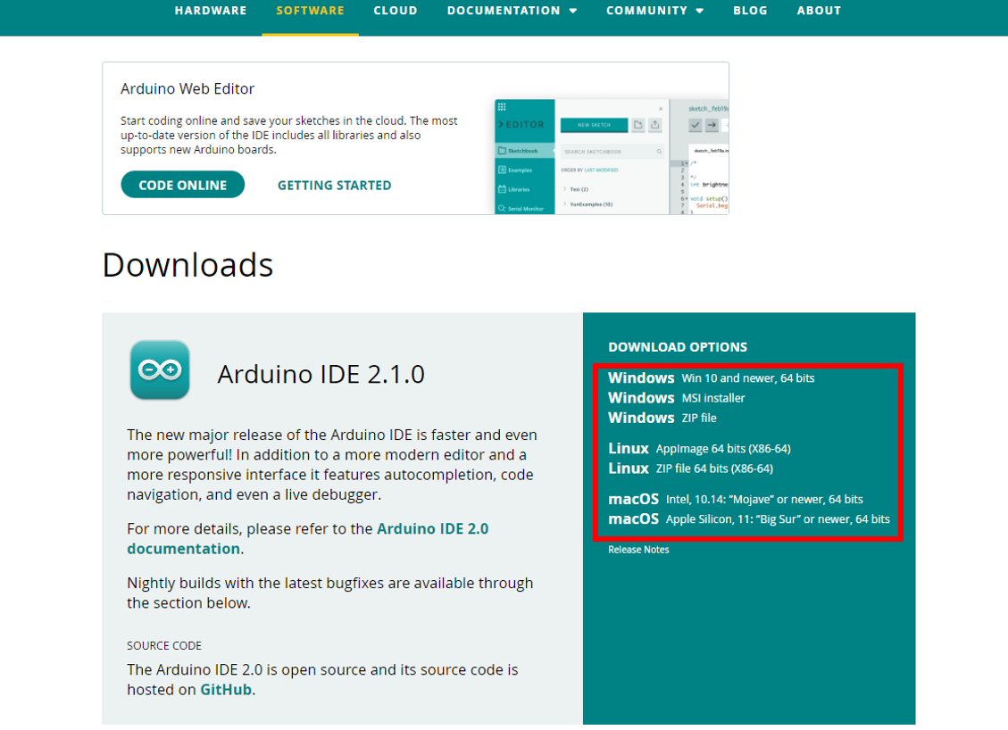 Figure 1: Download Options for the Arduino IDE
- Open the Arduino IDE and install the RAKwireless Arduino BSP for WisBlock using the
package_rakwireless_index.jsonboard installation package.
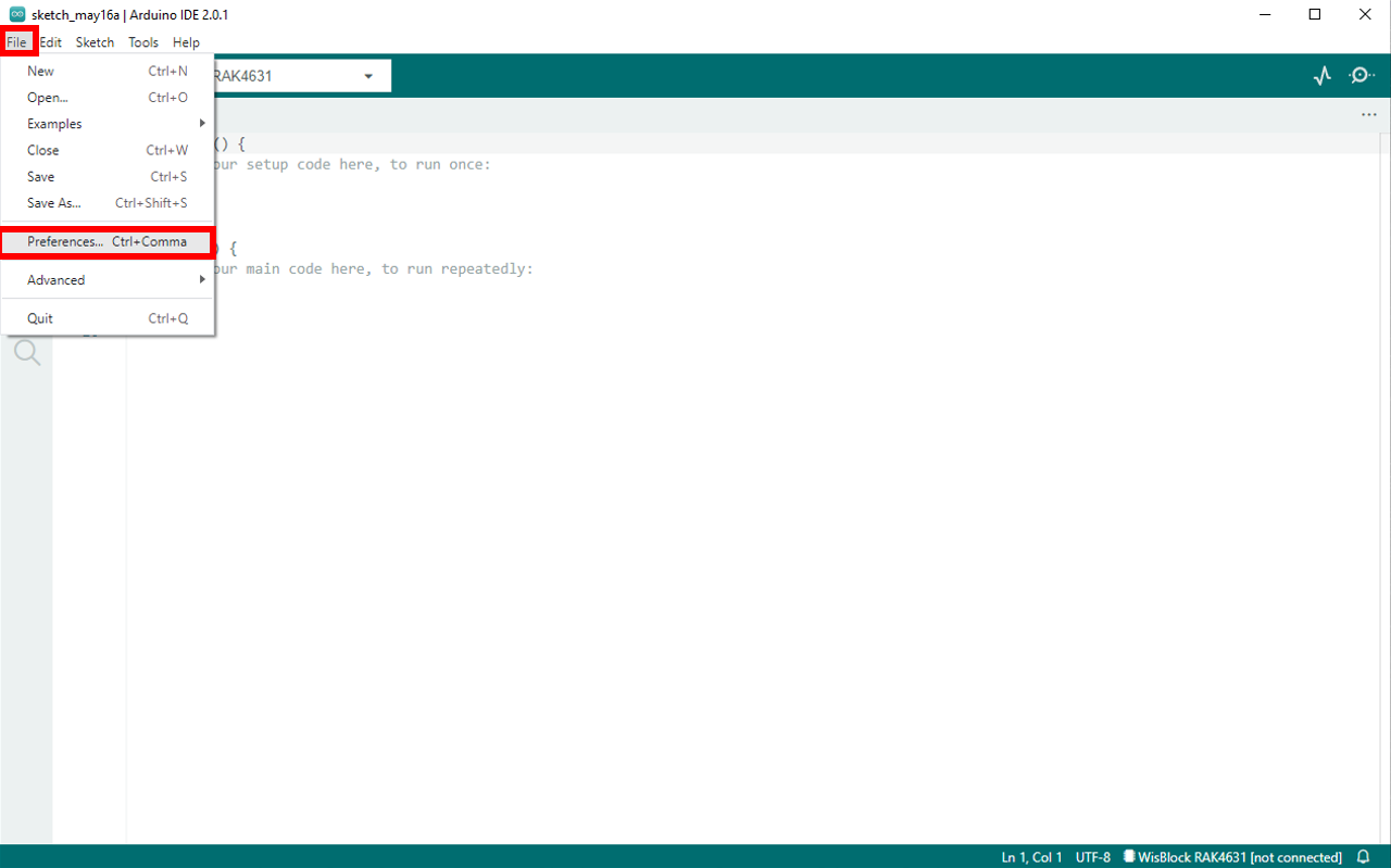 Figure 1: Preference Set-Up
- The WisBlock Core should now be available in the Arduino IDE; navigate to File > Preference to access it.
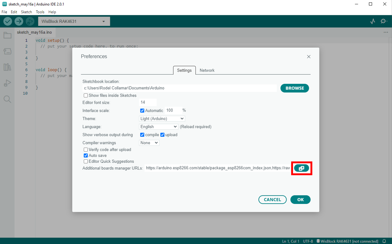 Figure 1: Preference Window
- In the Preference window, look for Additional Boards Manager URLs, then click the icon on the right side. Copy and paste the link, then click OK > OK.
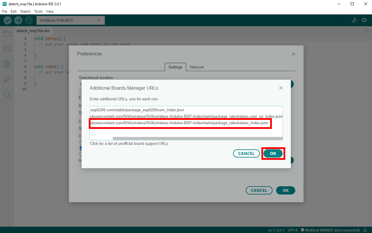 Figure 1: RAKwireless Arduino BSP
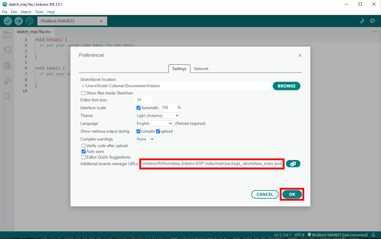 Figure 1: Completing the setup of the RAKwireless BSP support for the Arduino Board Manager
- Go to Tools > Board:XXXXX > Boards Manager.
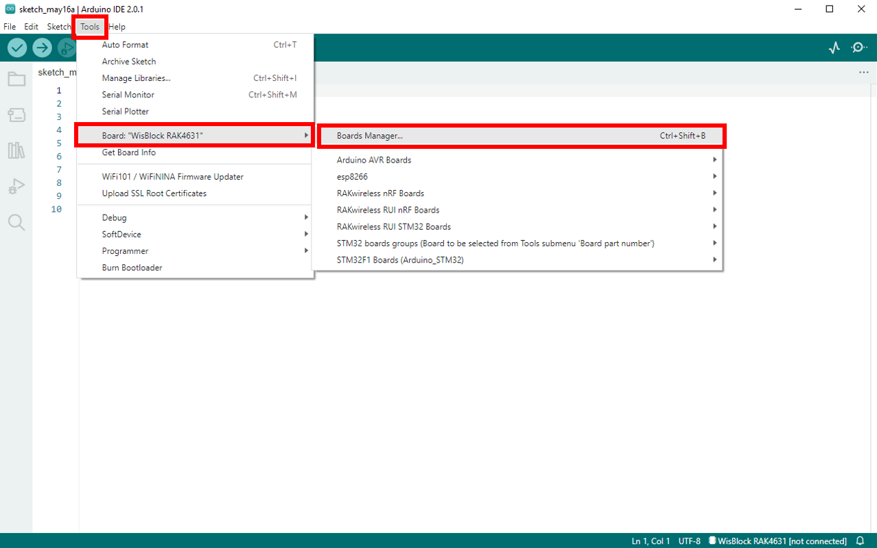 Figure 1: Opening the Boards Manager
- Look for RAKwireless Boards by RAKwireless since you will be working on the RAK4631 WisBlock Core. Choose the latest version, then install it. Once done, close the Board Manager.
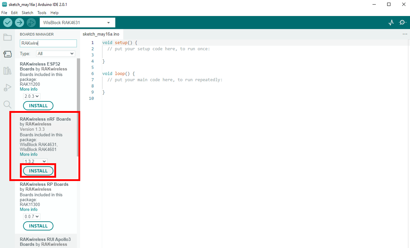 Figure 1: Installing the RAKwireless nRF Boards
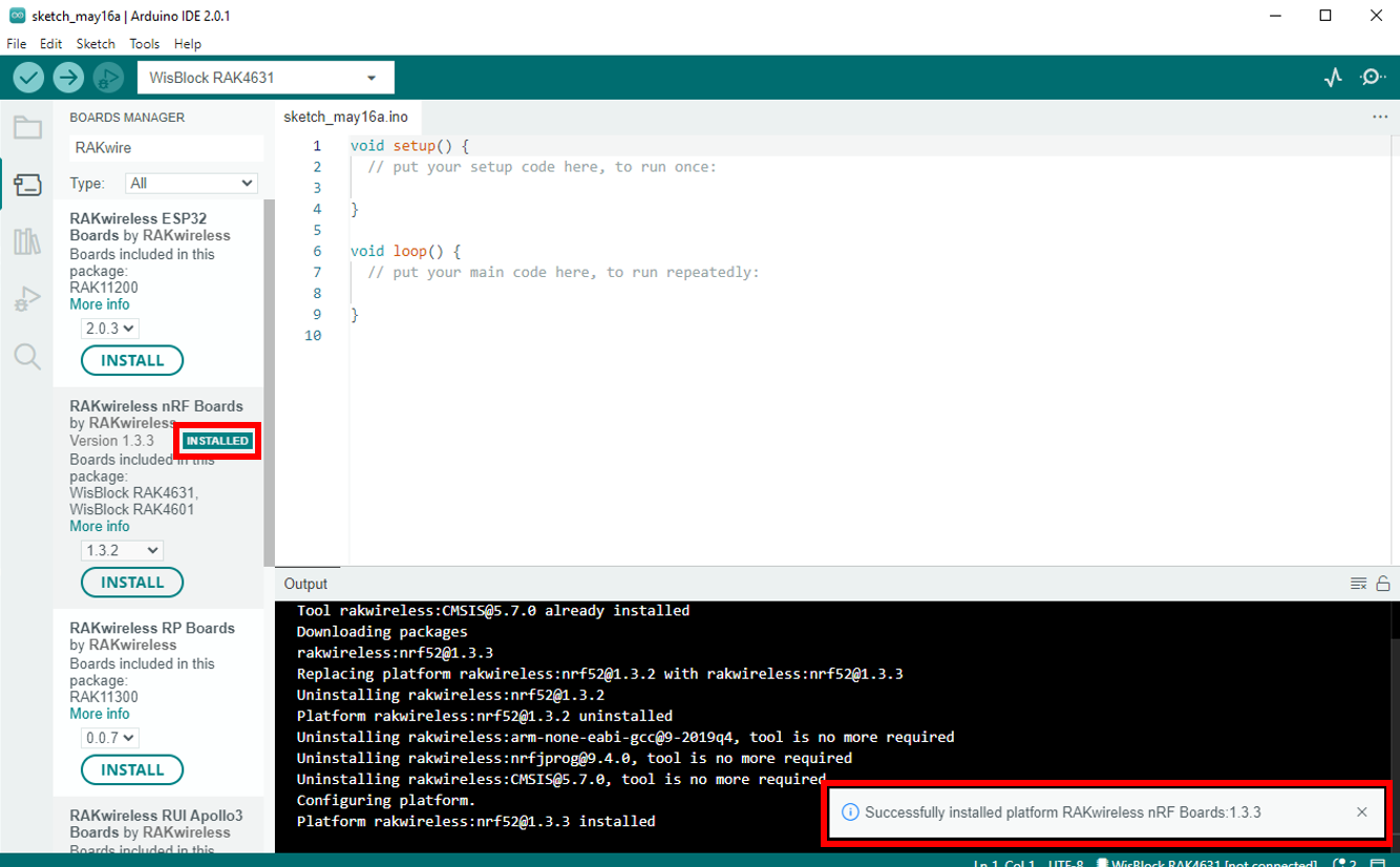 Figure 1: Successfully installed the RAKwireless nRF Boards
Once done with the Arduino IDE installation, proceed to LoRaWAN Code for Biometric Monitoring section.
