RAK14013 WisBlock Joystick Module Quick Start Guide
Prerequisite
Product Inclusions
Before going through each and every step on using the RAK14013 Joystick module, make sure to prepare the necessary items listed below:
Hardware
- RAK14013 WisBlock Joystick Module
- Your choice of WisBlock Base
- Your choice of WisBlock Core
- USB Cable
- RAK14007 WisBlock Interface Module
- Li-Ion/LiPo battery (optional)
- Solar charger (optional)
Software
- Download and install the Arduino IDE.
- To add the RAKwireless Core boards to your Arduino Boards Manager, install the RAKwireless Arduino BSP.
Product Configuration
Hardware Setup
The RAK14013 WisBlock Joystick Module can be mounted on the IO slot of the WisBlock Base board using RAK14007 WisBlock Interface Module, as shown in Figure 1. Also, always secure the connection of the WisBlock module by using compatible screws. For more information about RAK14013, refer to the Datasheet.
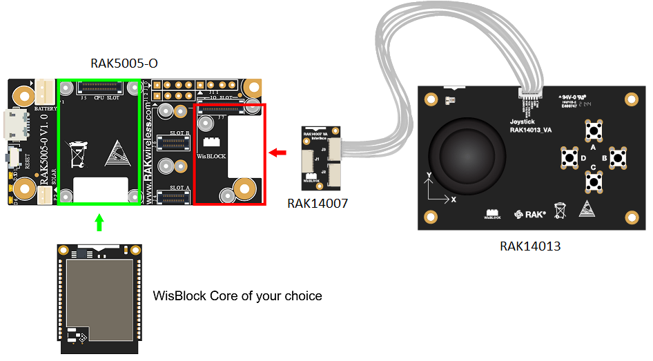 Figure 1: RAK14013 connection to WisBlock Base Board
Assembling and Disassembling of WisBlock Modules
Assembling
As shown in Figure 2, the location for the IO slot is properly marked by silkscreen. Follow carefully the procedure defined in RAK5005-O module assembly/disassembly instructions to attach a WisBlock module. Once attached, carefully fix the module with three pieces of M1.2 x 3 mm screws.
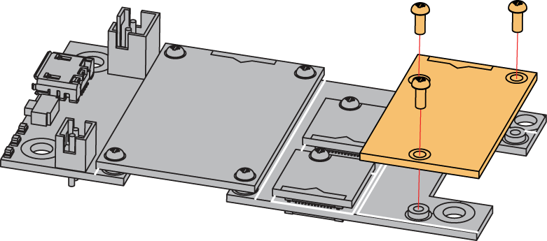 Figure 1: RAK14013 assembly to WisBlock Base Board
Disassembling
The procedure in disassembling any type of WisBlock module is the same.
- First, remove the screws.
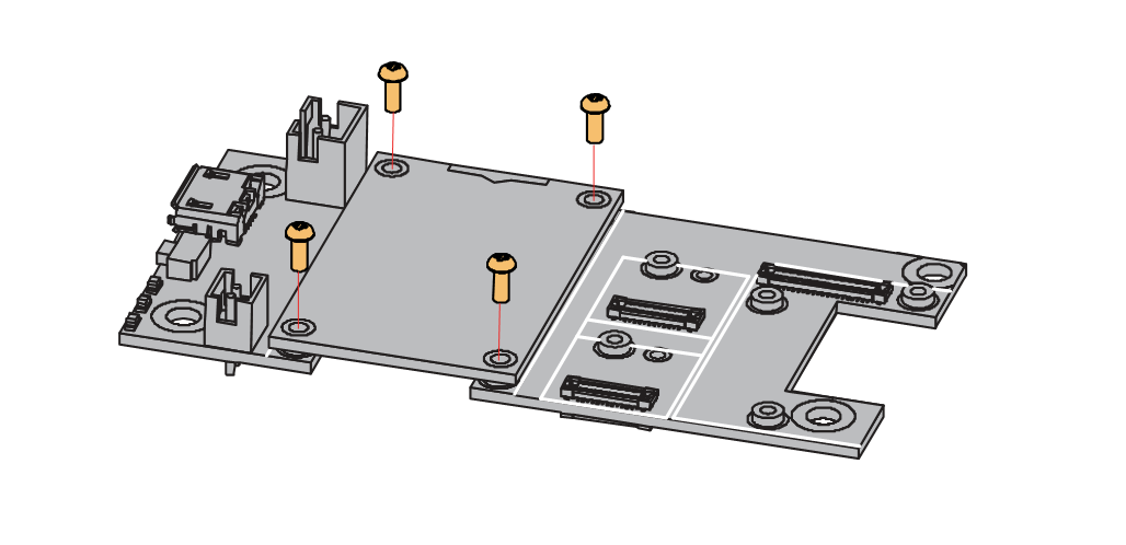 Figure 1: Removing screws from the WisBlock module
- Once the screws are removed, check the silkscreen of the module to find the correct location where force can be applied.
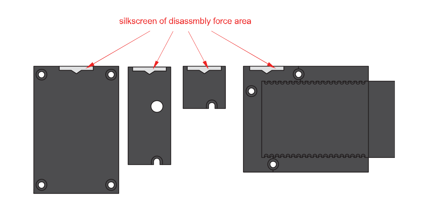 Figure 1: Detaching silkscreen on the WisBlock module
- Apply force to the module at the position of the connector, as shown in Figure 5, to detach the module from the baseboard.
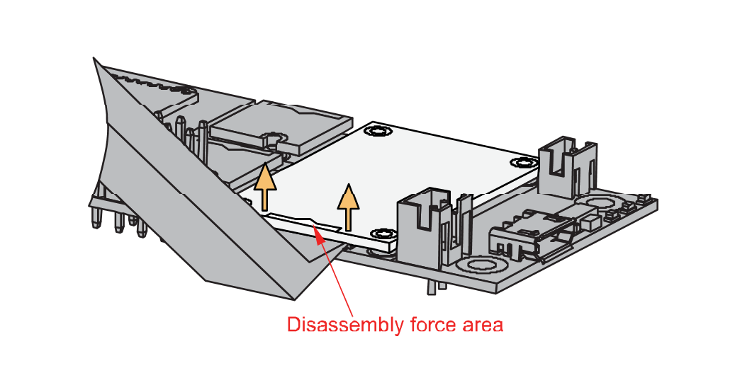 Figure 1: Applying even forces on the proper location of a WisBlock module
If you will connect other modules to the remaining WisBlock Base board slots, check on the WisBlock Pin Mapper tool for possible conflicts.
After all this setup, you can now connect the battery (optional) and USB cable to start programming your WisBlock Core.
- Batteries can cause harm if not handled properly.
- Only 3.7-4.2 V Rechargeable LiPo batteries are supported. It is highly recommended not to use other types of batteries with the system unless you know what you are doing.
- If a non-rechargeable battery is used, it has to be unplugged first before connecting the USB cable to the USB port of the board to configure the device. Not doing so might damage the battery or cause a fire.
- Only 5 V solar panels are supported. Do not use 12 V solar panels. It will destroy the charging unit and eventually other electronic parts.
- Make sure the battery wires match the polarity on the RAK5005-O board. Not all batteries have the same wiring.
Software Configuration and Example
In this example, you will be getting the rotation position of the knob or if it is pressed to your serial monitor.
- You need to select first the WisBlock Core you have, as shown in Figure 6 to Figure 8.
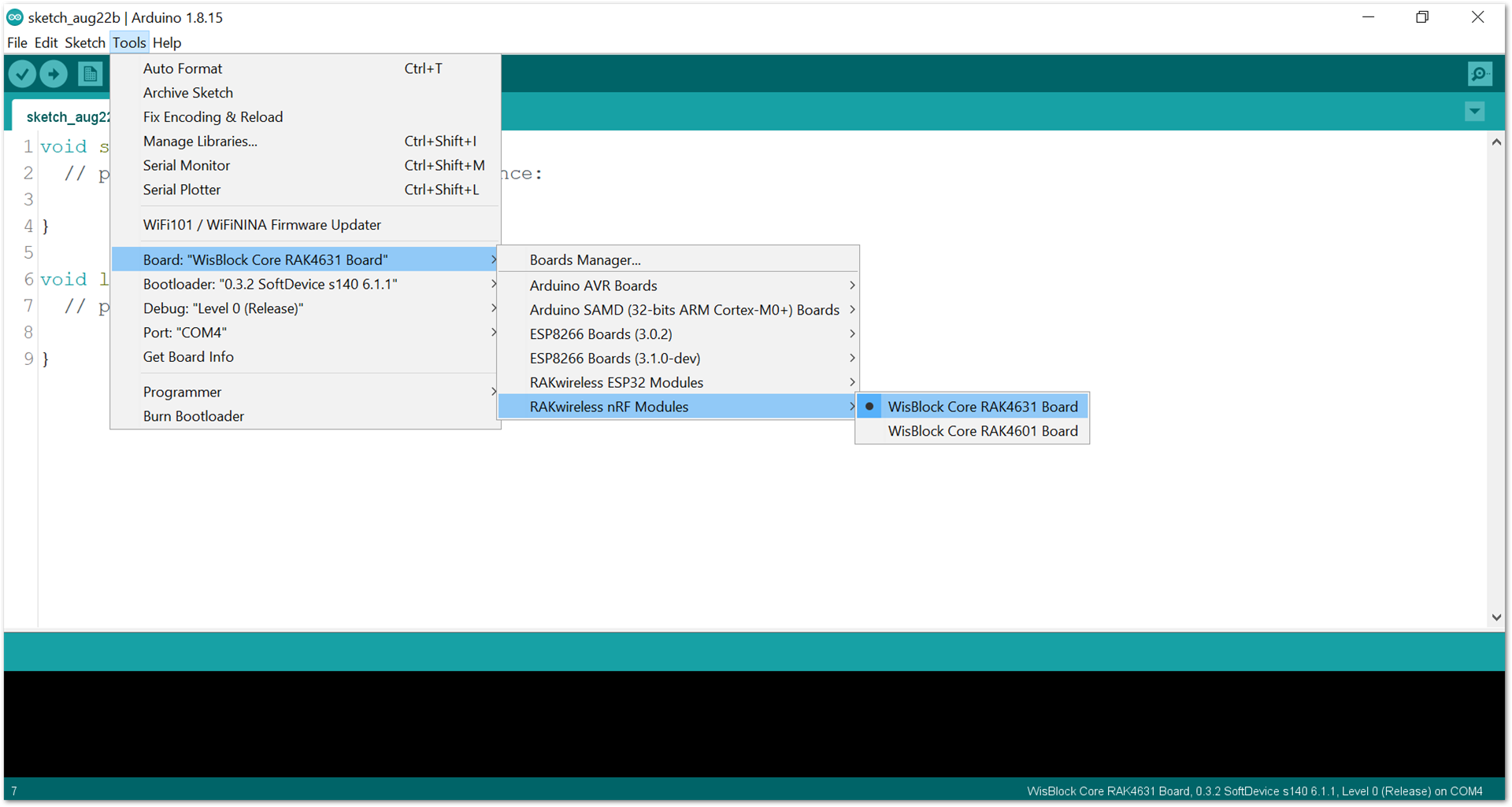 Figure 1: Selecting RAK4631 as WisBlock Core
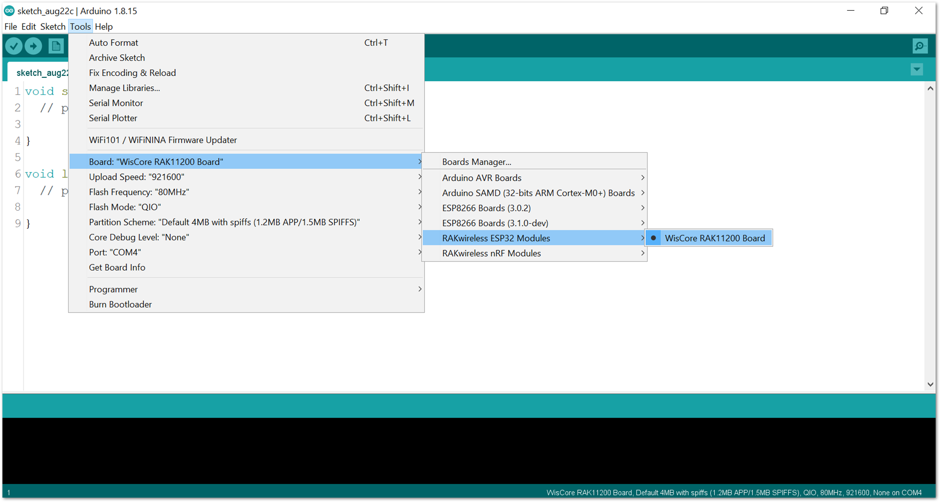 Figure 1: Selecting RAK11200 as WisBlock Core
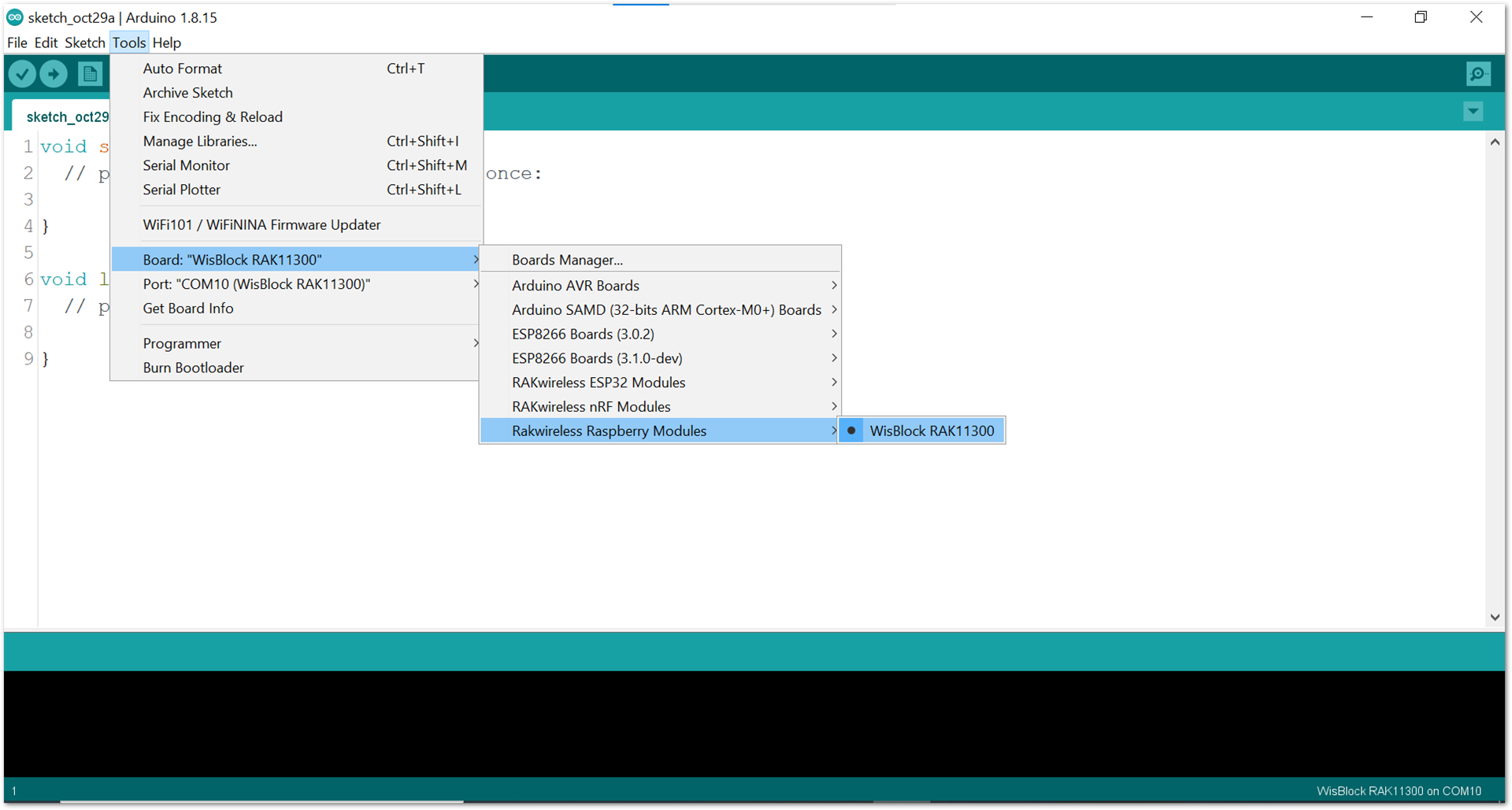 Figure 1: Selecting RAK11300 as WisBlock Core
- Copy the example code below:
Click to view the code
/**
   @file RAK14007_ATTINY441_Joystick.ino
   @author rakwireless.com
   @brief Joystick example
   @version 0.1
   @date 2021-7-28
   @copyright Copyright (c) 2020
**/
#include <Wire.h>

#define INT_LED                           35
#define SLAVE_I2C_ADDRESS_DEFAULT         0x21
//JOYSTICK Sensor Register Addresses
#define JOYSTICK_GET_DATA             0x01 // (r)   2 bytes
#define JOYSTICK_GET_I2C_ADDRESS      0x02  //(r)   1 bytes
#define JOYSTICK_SET_I2C_ADDRESS      0x03  //(w)   1 bytes
#define JOYSTICK_GET_VERSION          0x04 // (r)   1 bytes
#define JOYSTICK_SET_INT_TYPE         0x05 // (W)   1 bytes, five keys, from bit4-bit0, 0-push, 1-release.
#define JOYSTICK_GET_X_POSITION       0x06 // (r)   2 bytes, return the analog quantity. Range:0-1024, middle position is 507(near 512)
#define JOYSTICK_GET_Y_POSITION       0x07 // (r)   2 bytes, return the analog quantity. Range:0-1024, middle position is 507(near 512)
#define JOYSTICK_SET_X_LEFT_THREHOLD  0x08 // (w)   2 bytes, set the analog quantity. Range:0-1024
#define JOYSTICK_SET_X_RIGHT_THREHOLD 0x09 // (w)   2 bytes, set the analog quantity. Range:0-1024
#define JOYSTICK_SET_Y_UP_THREHOLD    0x0A // (w)   2 bytes, set the analog quantity. Range:0-1024
#define JOYSTICK_SET_Y_DOWN_THREHOLD  0x0B // (w)   2 bytes, set the analog quantity. Range:0-1024
#define JOYSTICK_GET_X_LEFT_THREHOLD  0x0C // (r)   2 bytes, get the analog quantity. Range:0-1024
#define JOYSTICK_GET_X_RIGHT_THREHOLD 0x0D // (r)   2 bytes, get the analog quantity. Range:0-1024
#define JOYSTICK_GET_Y_UP_THREHOLD    0x0E // (r)   2 bytes, get the analog quantity. Range:0-1024
#define JOYSTICK_GET_Y_DOWN_THREHOLD  0x0F // (r)   2 bytes, get the analog quantity. Range:0-1024

uint8_t flag = 0;

void detect()
{
  flag = 1;
  digitalWrite(35, HIGH);
}

//motion1       NA      NA     NA   keyE keyD keyC keyB keyA
//bit           7       6      5     4     3    2    1    0
//motion2       NA     NA     NA    NA    x-l   x-r  y-u  y-d
//bit           7       6      5     4     3    2    1    0
void judge()
{
  uint8_t data[2] = {0};
  uint8_t motion[2]  = {0}; //we use 8 bit to record the motion
  uint16_t tmp = 0;
  read_from_ttiny441(JOYSTICK_GET_DATA,motion,2);
  if((motion[0] & 0x01) == 0x01){Serial.println("KeyA Pressed");}
  if((motion[0] & 0x02) == 0x02){Serial.println("KeyB Pressed");}
  if((motion[0] & 0x04) == 0x04){Serial.println("KeyC Pressed");}
  if((motion[0] & 0x08) == 0x08){Serial.println("KeyD Pressed");}
  if((motion[0] & 0x10) == 0x10){Serial.println("KeyE Pressed");}
  if((motion[1] & 0x04) == 0x04)
  {
    tmp = 0;
    read_from_ttiny441(JOYSTICK_GET_X_POSITION,data,2);
    tmp = (((uint16_t)data[0]) << 8) | ((uint16_t)data[1]);
    if(tmp != 0xFFFF)
    {
       Serial.print("RIGHT ");
       Serial.print("X Position is ");
       Serial.println(tmp);
    }
  }
  if((motion[1] & 0x08) == 0x08)
  {
    tmp = 0;
    read_from_ttiny441(JOYSTICK_GET_X_POSITION,data,2);
    tmp = (((uint16_t)data[0]) << 8) | ((uint16_t)data[1]);
    if(tmp != 0xFFFF)
    {
       Serial.print("LEFT ");
       Serial.print("X Position is ");
       Serial.println(tmp);
    }
  }
  if((motion[1] & 0x02) == 0x02)
  {
    tmp = 0;
    read_from_ttiny441(JOYSTICK_GET_Y_POSITION,data,2);
    tmp = (((uint16_t)data[0]) << 8) | ((uint16_t)data[1]);
    if(tmp != 0xFFFF)
    {
       Serial.print("UP ");
       Serial.print("Y Position is ");
       Serial.println(tmp);
    }
  }
  if((motion[1] & 0x01) == 0x01)
  {
    tmp = 0;
    read_from_ttiny441(JOYSTICK_GET_Y_POSITION,data,2);
    tmp = (((uint16_t)data[0]) << 8) | ((uint16_t)data[1]);
    if(tmp != 0xFFFF)
    {
       Serial.print("DOWN ");
       Serial.print("Y Position is ");
       Serial.println(tmp);
    }
  }
  digitalWrite(INT_LED, LOW);
}

void setup() {
  pinMode(WB_IO2, OUTPUT);
  digitalWrite(WB_IO2, HIGH);
  pinMode(INT_LED, OUTPUT);
  digitalWrite(INT_LED, LOW);
  Serial.begin(115200);
  Serial.print("Joystick Test!");
  Wire.begin();
  delay(1000);
  uint8_t data = 0;
  read_from_ttiny441(JOYSTICK_GET_VERSION,&data,1);
  Serial.print("Sensor Firmware version: ");
  Serial.println(data,HEX);
  Serial.println();
  //here we use interrupt to notify
  pinMode(WB_IO6, INPUT);
  attachInterrupt(WB_IO6, detect, RISING);
  //set interrupt type for each key. 0 for push/ 1 for release. This step is necessary.
  uint8_t itp = 0x00;
  write_to_ttiny441(JOYSTICK_SET_INT_TYPE,&itp,1);
}

void loop() {
  if(flag == 1)
  {
    //slave interrupt will clear after host read
    judge();
    flag = 0;
  }
  delay(10);
}

void read_from_ttiny441(uint8_t reg, uint8_t *data, uint8_t length)
{
  Wire.beginTransmission(SLAVE_I2C_ADDRESS_DEFAULT);
  Wire.write(reg);        // sends five bytes
  Wire.endTransmission();    // stop transmitting
  delay(20);
  Wire.requestFrom(SLAVE_I2C_ADDRESS_DEFAULT,length);
  int i = 0;
  while ( Wire.available() ) // slave may send less than requested
  {
    data[i++]= Wire.read(); // receive a byte as a proper uint8_t
  }
}

void write_to_ttiny441(uint8_t reg, uint8_t *data, uint8_t length)
{
  Wire.beginTransmission(SLAVE_I2C_ADDRESS_DEFAULT);
  Wire.write(reg);        // sends five bytes
  for(int i=0;i<length;i++)
  {
    Wire.write(data[i]);
  }
  Wire.endTransmission();    // stop transmitting
}
If you experience any error in compiling the example sketch, check the updated code for the RAK14013 WisBlock Joystick Module that can be found on the RAK14013 WisBlock Example Code Repository.
- Select the right serial port and upload the code, as shown in Figure 9 and Figure 10.
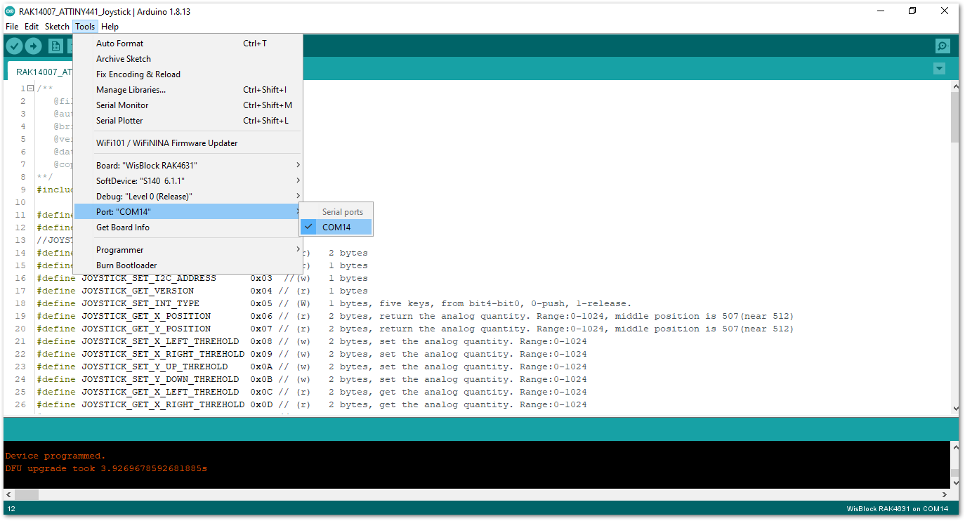 Figure 1: Selecting the correct serial port
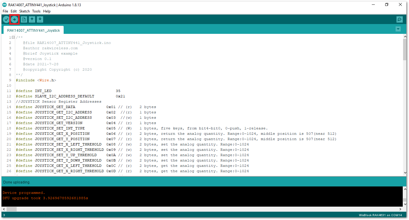 Figure 1: Uploading the sample code
RAK11200 requires the BOOT0 pin to be configured properly before uploading. If not done properly, uploading the source code to RAK11200 will fail. Check the full details on the RAK11200 Quick Start Guide.
- When you have successfully uploaded the sample code, you may rotate or press the joystick and buttons of RAK14013. Then you can open up your serial monitor to get the joystick reading, as shown in Figure 11.
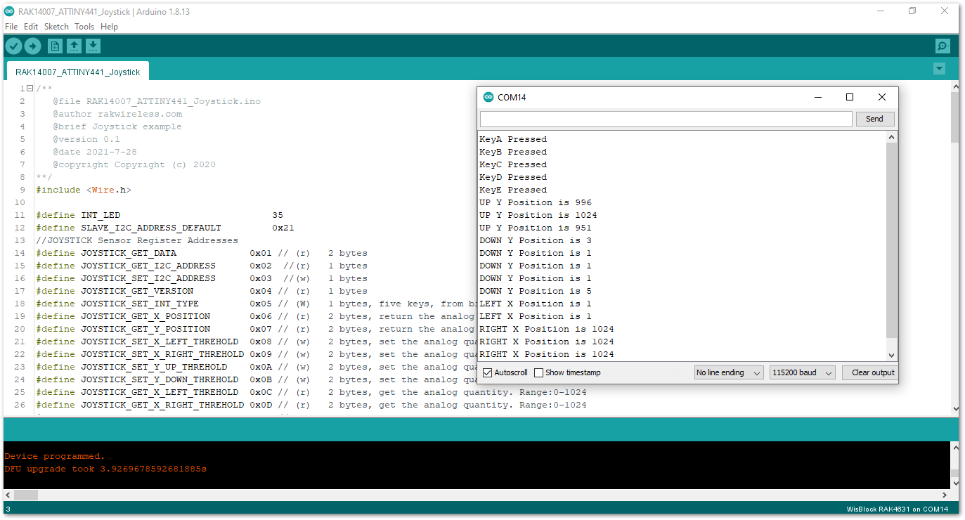 Figure 1: Position readings in serial monitor