RAK1905 WisBlock 9-Axis Sensor Module Quick Start Guide
Prerequisite
What Do You Need?
Before going through each and every step on using the RAK1905 WisBlock module, make sure to prepare the necessary items listed below:
Hardware
- RAK1905 WisBlock VOC Sensor Module
- Your choice of WisBlock Base
- Your choice of WisBlock Core
- USB Cable
- Li-Ion/LiPo battery (optional)
- Solar charger (optional)
Software
- Download and install the Arduino IDE.
- Install the RAKwireless Arduino BSP and add the RAKwireless Core boards to your Arduino Boards Manager. Follow the steps in the GitHub repo.
Product Configuration
Hardware Setup
The RAK1905 combined with any WisBlock Core module is a ready-to-go system for navigation, orientation measurement, tilt sensing, platform stabilization, and robotic systems. The acquired data can be sent using LoRaWAN communication, LoRa Point-to-Point connections, BLE, or WiFi, depending on the Core module.
For more information about the RAK1905, refer to the Datasheet.
RAK1905 module can be connected to the sensor's slot of WisBlock Base to communicate with the WisBlock Core, as shown in Figure 1. It will work on SLOT A to F. Also, always secure the connection of the WisBlock module by using compatible screws.
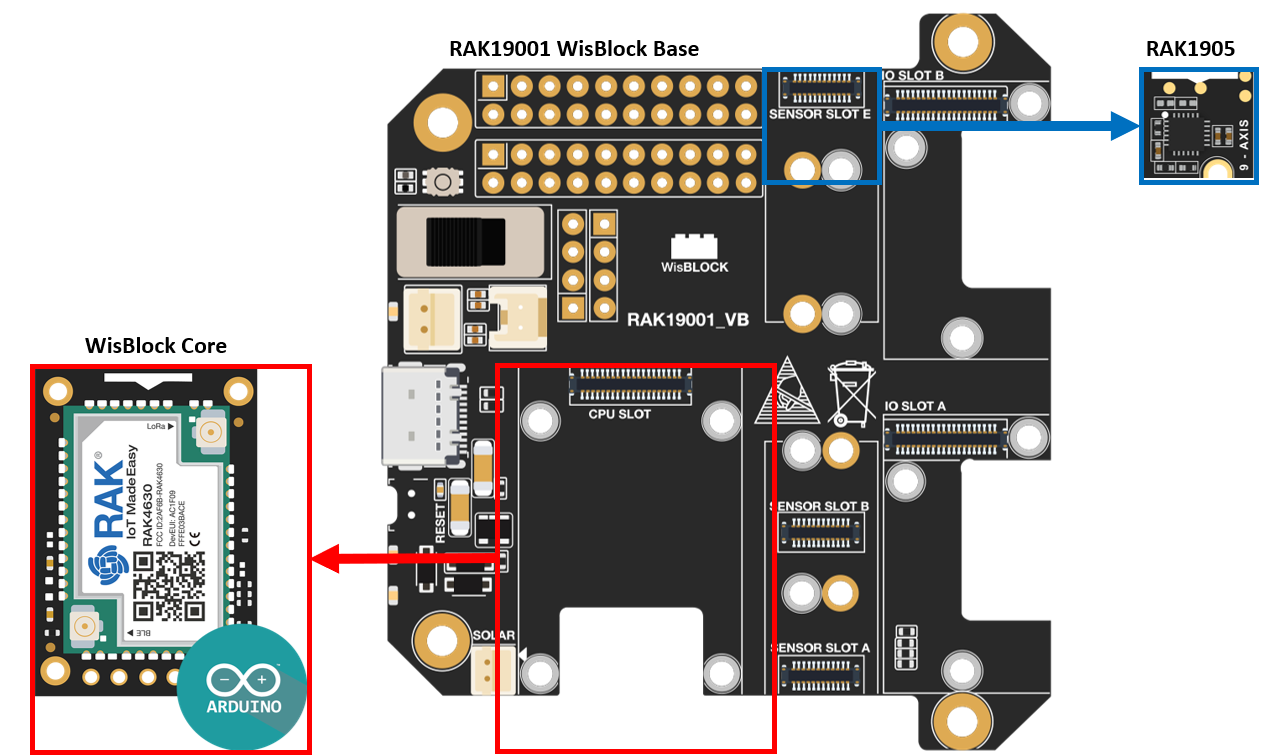 Figure 1: RAK11905 connection to WisBlock Base
Assembling and Disassembling of WisBlock Modules
Assembling
As shown in Figure 2, the location for Slots A, B, C, D, E, and F are properly marked by silkscreen. Slots C and D are located on the bottom of the WisBlock Base. Follow carefully the procedure defined in WisBlock Base board assembly/disassembly instructions to attach a WisBlock module. Once attached, carefully fix the module with an M1.2 x 3 mm screw.
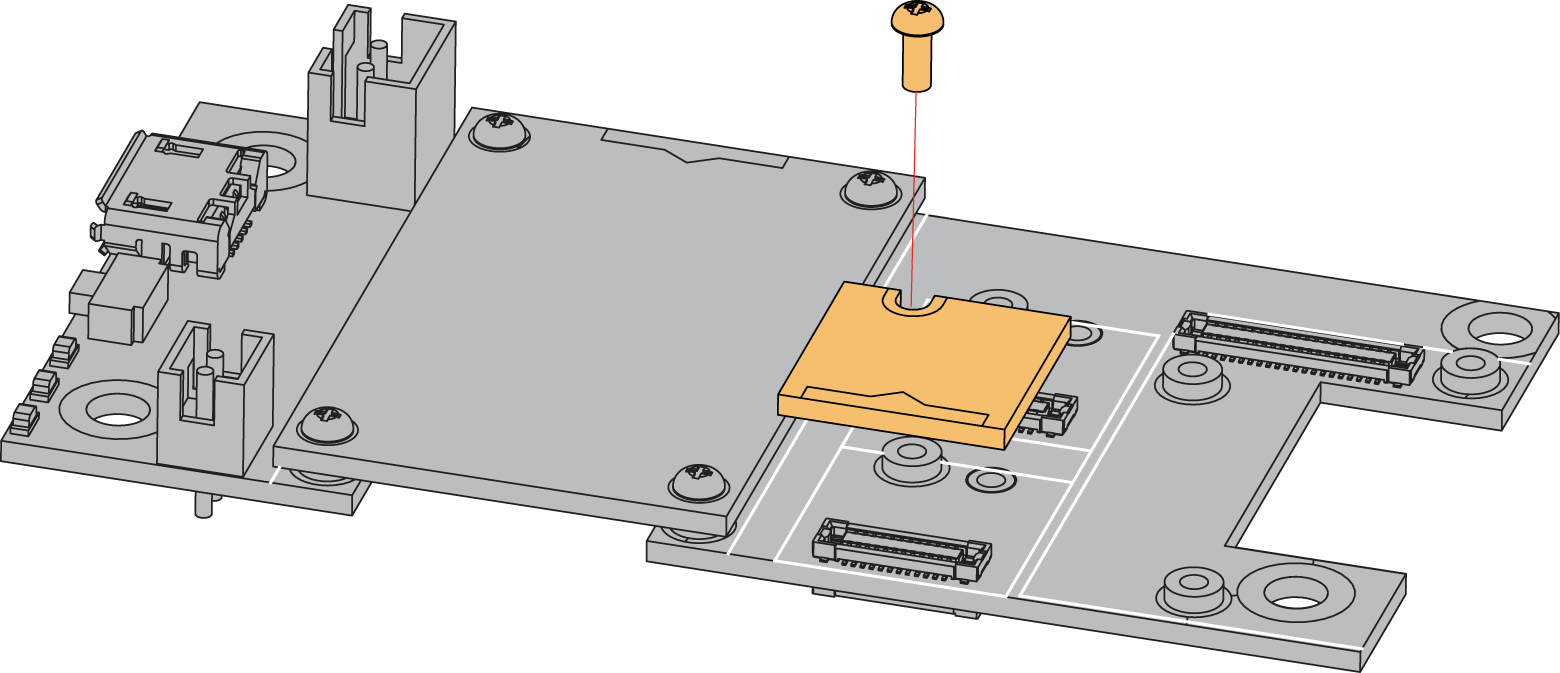 Figure 1: RAK1905 connection to WisBlock Base
Disassembling
The procedure in disassembling any type of WisBlock module is the same.
- Remove the screws.
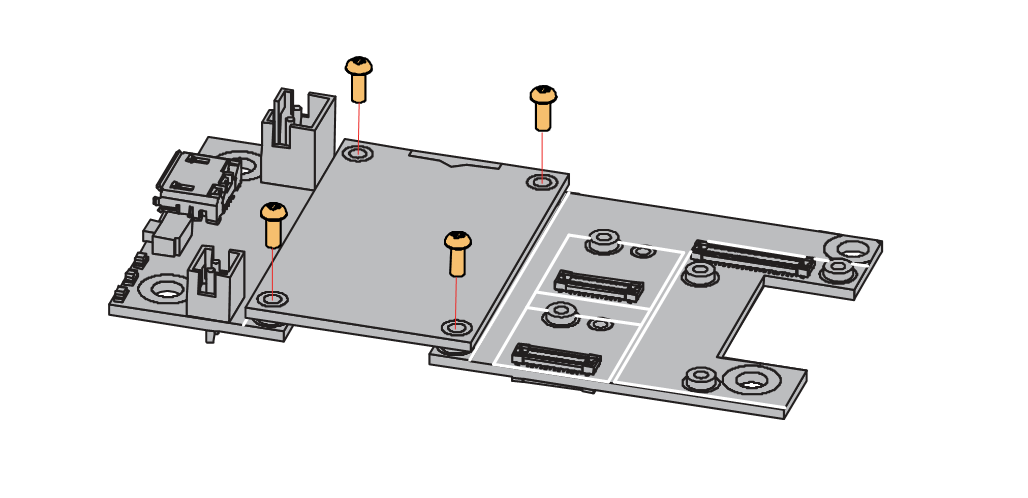 Figure 1: Removing screws from the WisBlock module
- Once the screws are removed, check the silkscreen of the module to find the correct location where force can be applied.
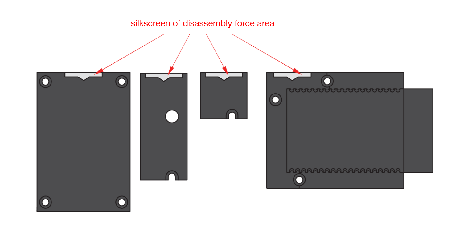 Figure 1: Detaching silkscreen on the WisBlock module
- Apply force to the module at the position of the connector, as shown in Figure 5, to detach the module from the baseboard.
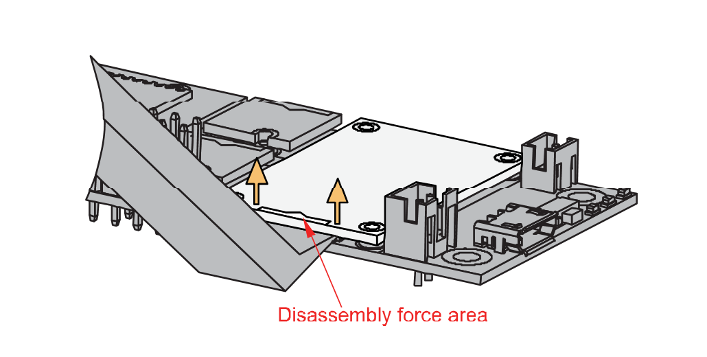 Figure 1: Applying even forces on the proper location of a WisBlock module
If you will connect other modules to the remaining WisBlock Base slots, check on the WisBlock Pin Mapper tool for possible conflicts. RAK1905 uses I2C communication lines, and it can cause possible conflict, especially on some IO modules.
After all this setup, you can now connect the battery (optional) and USB cable to start programming your WisBlock Core.
- Batteries can cause harm if not handled properly.
- Only 3.7-4.2 V rechargeable LiPo batteries are supported. It is highly recommended not to use other types of batteries with the system unless you know what you are doing.
- If a non-rechargeable battery is used, it has to be unplugged first before connecting the USB cable to the USB port of the board to configure the device. Not doing so might damage the battery or cause a fire.
- Only 5 V solar panels are supported. Do not use 12 V solar panels. It will destroy the charging unit and eventually other electronic parts.
- Make sure the battery wires match the polarity on the WisBlock Base board. Not all batteries have the same wiring.
Software Configuration and Example
Initial Test of the RAK1905 WisBlock Module
-
Install the RAKwireless Arduino BSPs for WisBlock by using the
package_rakwireless_index.jsonboard installation package, the WisBlock Core should now be available on the Arduino IDE. -
You need to select the WisBlock Core you have.
RAK4631 WisBlock Core
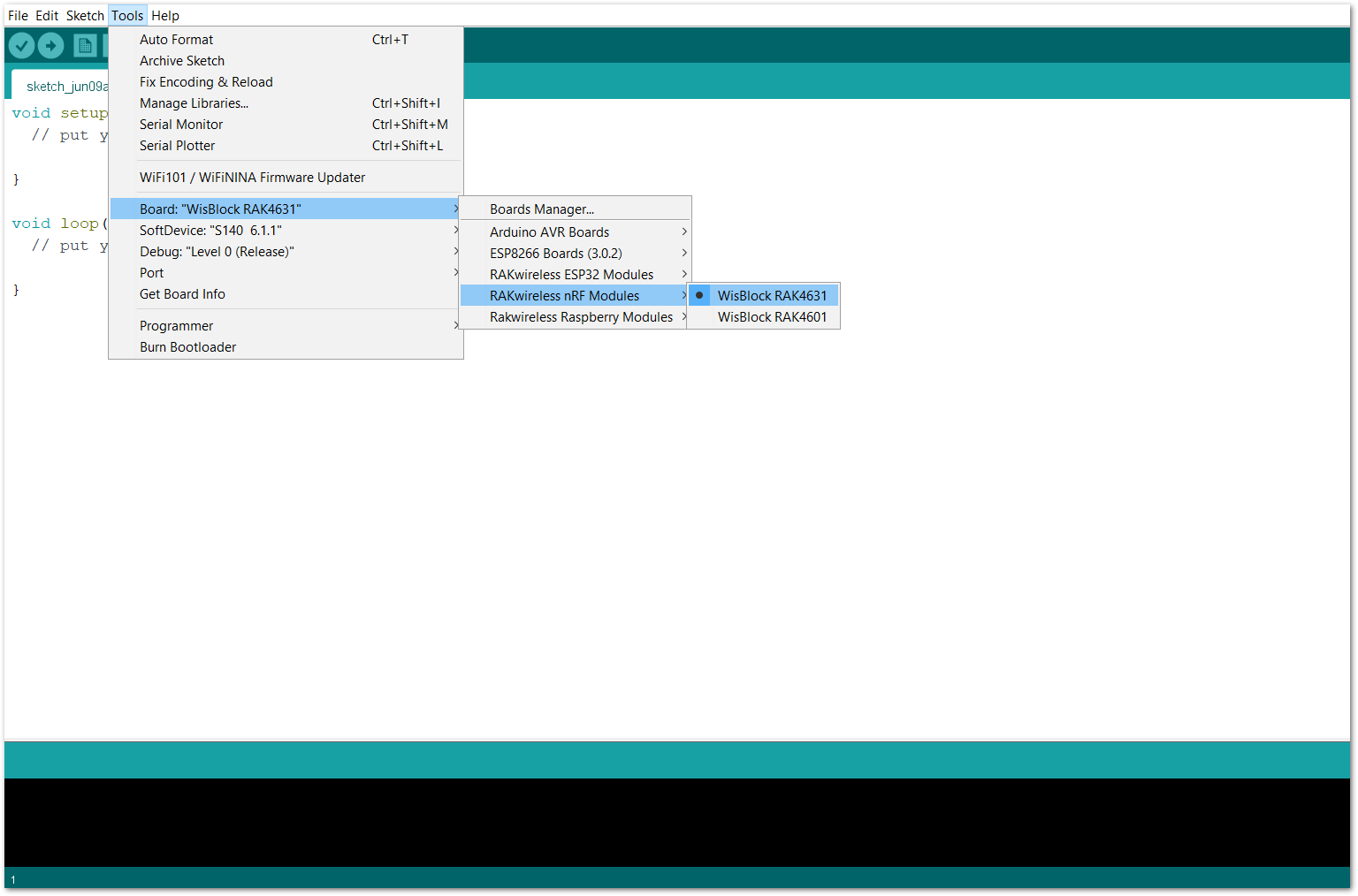 Figure 1: Selecting RAK4631 as WisBlock Core
RAK11200 WisBlock Core
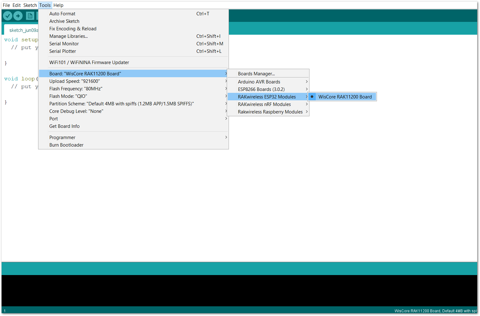 Figure 1: Selecting RAK11200 as WisBlock Core
RAK11310 WisBlock Core
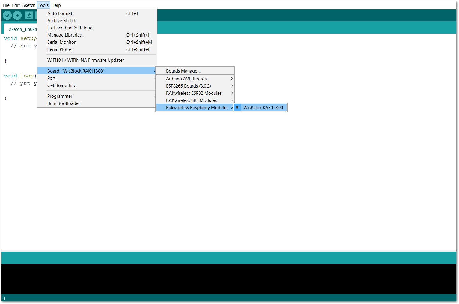 Figure 1: Selecting RAK11310 as WisBlock Core
- Copy the following sample code into your Arduino IDE:
Click to view the code
/**
   @file MPU9250_all_data.ino
   @author rakwireless.com
   @brief  This sketch shows how to get acceleration, gyroscocope, magnetometer and
           temperature data from the MPU9250. It might be a bit confusing with all the
           settings. Therefore you will also find sketches for the individual data.
   @version 0.1
   @date 2022-03-17
   @copyright Copyright (c) 2022
**/

#include <MPU9250_WE.h>
#include <Wire.h>
#define MPU9250_ADDR 0x68   // library: http://librarymanager/All#MPU9250_WE

/* There are several ways to create your MPU9250 object:
   MPU9250_WE myMPU9250 = MPU9250_WE()              -> uses Wire / I2C Address = 0x68
   MPU9250_WE myMPU9250 = MPU9250_WE(MPU9250_ADDR)  -> uses Wire / MPU9250_ADDR
   MPU9250_WE myMPU9250 = MPU9250_WE(&wire2)        -> uses the TwoWire object wire2 / MPU9250_ADDR
   MPU9250_WE myMPU9250 = MPU9250_WE(&wire2, MPU9250_ADDR) -> all together
   Successfully tested with two I2C busses on an ESP32
*/
MPU9250_WE myMPU9250 = MPU9250_WE(MPU9250_ADDR);

void setup() {
  pinMode(LED_BLUE, OUTPUT);
  digitalWrite(LED_BLUE, HIGH);
  time_t timeout = millis();
  Serial.begin(115200);
  while (!Serial)
  {
    if ((millis() - timeout) < 5000)
    {
      delay(100);
    }
    else
    {
      break;
    }
  }
  Wire.begin();
  if (!myMPU9250.init()) {
    Serial.println("MPU9250 does not respond");
    while (1) delay(100);
  }
  else {
    Serial.println("MPU9250 is connected");
  }
  if (!myMPU9250.initMagnetometer()) {
    Serial.println("Magnetometer does not respond");
    while (1) delay(100);
  }
  else {
    Serial.println("Magnetometer is connected");
  }

    Serial.println("RAK1905 Test!");
  /* The slope of the curve of acceleration vs measured values fits quite well to the theoretical
     values, e.g. 16384 units/g in the +/- 2g range. But the starting point, if you position the
     MPU9250 flat, is not necessarily 0g/0g/1g for x/y/z. The autoOffset function measures offset
     values. It assumes your MPU9250 is positioned flat with its x,y-plane. The more you deviate
     from this, the less accurate will be your results.
     The function also measures the offset of the gyroscope data. The gyroscope offset does not
     depend on the positioning.
     This function needs to be called at the beginning since it can overwrite your settings!
  */
  Serial.println("Position you MPU9250 flat and don't move it - calibrating...");
  delay(1000);
  myMPU9250.autoOffsets();
  Serial.println("Done!");

  /*  This is a more accurate method for calibration. You have to determine the minimum and maximum
      raw acceleration values of the axes determined in the range +/- 2 g.
      You call the function as follows: setAccOffsets(xMin,xMax,yMin,yMax,zMin,zMax);
      Use either autoOffset or setAccOffsets, not both.
  */
  //myMPU9250.setAccOffsets(-14240.0, 18220.0, -17280.0, 15590.0, -20930.0, 12080.0);

  /*  The gyroscope data is not zero, even if you don't move the MPU9250.
      To start at zero, you can apply offset values. These are the gyroscope raw values you obtain
      using the +/- 250 degrees/s range.
      Use either autoOffset or setGyrOffsets, not both.
  */
  //myMPU9250.setGyrOffsets(45.0, 145.0, -105.0);

  /*  You can enable or disable the digital low pass filter (DLPF). If you disable the DLPF, you
      need to select the bandwdith, which can be either 8800 or 3600 Hz. 8800 Hz has a shorter delay,
      but higher noise level. If DLPF is disabled, the output rate is 32 kHz.
      MPU9250_BW_WO_DLPF_3600
      MPU9250_BW_WO_DLPF_8800
  */
  myMPU9250.enableGyrDLPF();
  //myMPU9250.disableGyrDLPF(MPU9250_BW_WO_DLPF_8800); // bandwdith without DLPF

  /*  Digital Low Pass Filter for the gyroscope must be enabled to choose the level.
      MPU9250_DPLF_0, MPU9250_DPLF_2, ...... MPU9250_DPLF_7
      DLPF    Bandwidth [Hz]   Delay [ms]   Output Rate [kHz]
        0         250            0.97             8
        1         184            2.9              1
        2          92            3.9              1
        3          41            5.9              1
        4          20            9.9              1
        5          10           17.85             1
        6           5           33.48             1
        7        3600            0.17             8
        You achieve lowest noise using level 6
  */
  myMPU9250.setGyrDLPF(MPU9250_DLPF_6);

  /*  Sample rate divider divides the output rate of the gyroscope and accelerometer.
      Sample rate = Internal sample rate / (1 + divider)
      It can only be applied if the corresponding DLPF is enabled and 0<DLPF<7!
      Divider is a number 0...255
  */
  myMPU9250.setSampleRateDivider(5);

  /*  MPU9250_GYRO_RANGE_250       250 degrees per second (default)
      MPU9250_GYRO_RANGE_500       500 degrees per second
      MPU9250_GYRO_RANGE_1000     1000 degrees per second
      MPU9250_GYRO_RANGE_2000     2000 degrees per second
  */
  myMPU9250.setGyrRange(MPU9250_GYRO_RANGE_250);

  /*  MPU9250_ACC_RANGE_2G      2 g   (default)
      MPU9250_ACC_RANGE_4G      4 g
      MPU9250_ACC_RANGE_8G      8 g
      MPU9250_ACC_RANGE_16G    16 g
  */
  myMPU9250.setAccRange(MPU9250_ACC_RANGE_2G);

  /*  Enable/disable the digital low pass filter for the accelerometer
      If disabled the bandwidth is 1.13 kHz, delay is 0.75 ms, output rate is 4 kHz
  */
  myMPU9250.enableAccDLPF(true);

  /*  Digital low pass filter (DLPF) for the accelerometer, if enabled
      MPU9250_DPLF_0, MPU9250_DPLF_2, ...... MPU9250_DPLF_7
       DLPF     Bandwidth [Hz]      Delay [ms]    Output rate [kHz]
         0           460               1.94           1
         1           184               5.80           1
         2            92               7.80           1
         3            41              11.80           1
         4            20              19.80           1
         5            10              35.70           1
         6             5              66.96           1
         7           460               1.94           1
  */
  myMPU9250.setAccDLPF(MPU9250_DLPF_6);

  /* You can enable or disable the axes for gyroscope and/or accelerometer measurements.
     By default all axes are enabled. Parameters are:
     MPU9250_ENABLE_XYZ  //all axes are enabled (default)
     MPU9250_ENABLE_XY0  // X, Y enabled, Z disabled
     MPU9250_ENABLE_X0Z
     MPU9250_ENABLE_X00
     MPU9250_ENABLE_0YZ
     MPU9250_ENABLE_0Y0
     MPU9250_ENABLE_00Z
     MPU9250_ENABLE_000  // all axes disabled
  */
  //myMPU9250.enableAccAxes(MPU9250_ENABLE_XYZ);
  //myMPU9250.enableGyrAxes(MPU9250_ENABLE_XYZ);

  /*
     AK8963_PWR_DOWN
     AK8963_CONT_MODE_8HZ         default
     AK8963_CONT_MODE_100HZ
     AK8963_FUSE_ROM_ACC_MODE
  */
  myMPU9250.setMagOpMode(AK8963_CONT_MODE_100HZ);
  delay(200);
}

void loop() {
  xyzFloat gValue = myMPU9250.getGValues();
  xyzFloat gyr = myMPU9250.getGyrValues();
  xyzFloat magValue = myMPU9250.getMagValues();
  float temp = myMPU9250.getTemperature();
  float resultantG = myMPU9250.getResultantG(gValue);

  Serial.println("Acceleration in g (x,y,z):");
  Serial.print(gValue.x);
  Serial.print("   ");
  Serial.print(gValue.y);
  Serial.print("   ");
  Serial.println(gValue.z);
  Serial.print("Resultant g: ");
  Serial.println(resultantG);

  Serial.println("Gyroscope data in degrees/s: ");
  Serial.print(gyr.x);
  Serial.print("   ");
  Serial.print(gyr.y);
  Serial.print("   ");
  Serial.println(gyr.z);

  Serial.println("Magnetometer Data in µTesla: ");
  Serial.print(magValue.x);
  Serial.print("   ");
  Serial.print(magValue.y);
  Serial.print("   ");
  Serial.println(magValue.z);

  Serial.print("Temperature in °C: ");
  Serial.println(temp);

  Serial.println("********************************************");

  delay(1000);
}
If you experience any error in compiling the example sketch, check the updated code for your WisBlock Core Module that can be found on the RAK1905 WisBlock Example Code Repository and this sample code in GitHub will work on all WisBlock Core.
- Once the example code is open, install the MPU9250_WE library by clicking the link highlighted in yellow, as shown in Figure 9 and Figure 10.
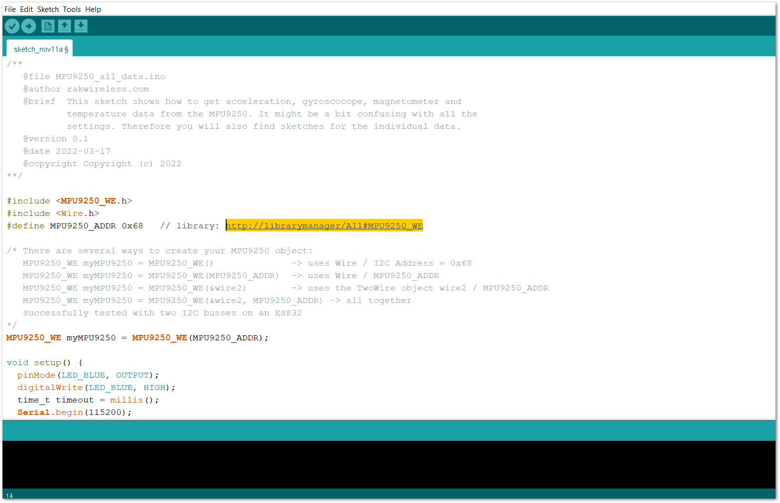 Figure 1: Accessing the library used for RAK1905 Module
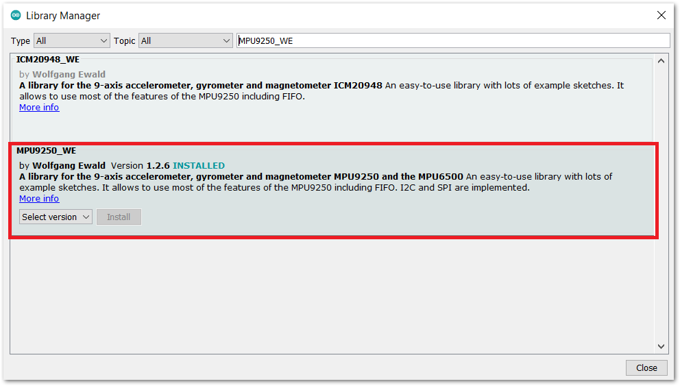 Figure 1: Installing the compatible library for RAK1905 Module
- After successful installation of the library, you can now select the right serial port and upload the code, as shown in Figure 11 and Figure 12.
If you are using the RAK11200 as your WisBlock Core, the RAK11200 requires the Boot0 pin to be configured properly first before uploading. If not done properly, uploading the source code to RAK11200 will fail. Check the full details on the RAK11200 Quick Start Guide.
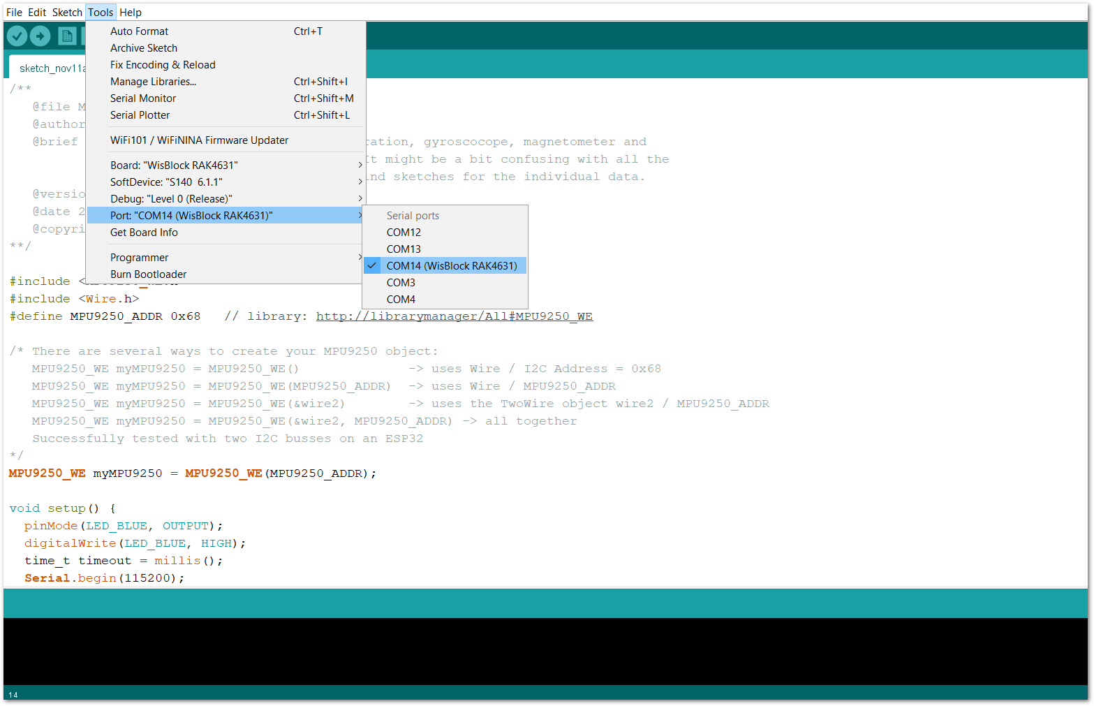 Figure 1: Selecting the correct serial port
 Figure 1: Uploading the RAK1905 example code
- When you have successfully uploaded the example sketch, open the serial monitor of the Arduino IDE and set the baud rate correctly. Try to move the device to any direction, position, or motion, then you will then see the sensor's output, as shown in Figure 13. Therefore, your RAK1905 is properly communicating to the WisBlock core.
After powering up, the sensor is calibrating itself and during this time, the sensor MUST NOT be moved.
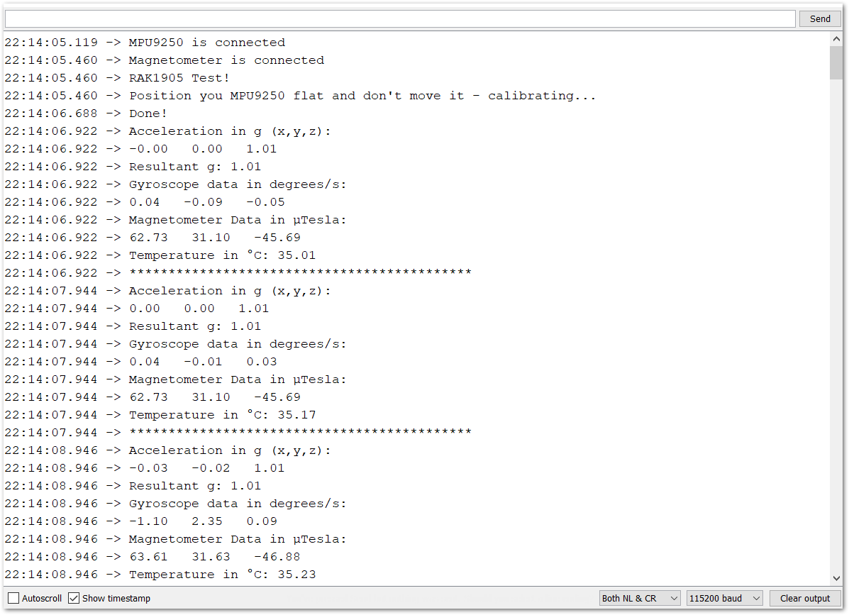 Figure 1: RAK1905 9DOF Sensor Module data logs