RAK1910 WisBlock GNSS Location Module Quick Start Guide
This guide introduces the RAK1910 WisBlock GNSS Location Module and how to program with it. The information obtained from the GPS will then be printed over the USB debug port of the WisBlock Base board.
Prerequisite
What Do You Need?
Before going through each and every step on using the RAK1910 WisBlock module, make sure to prepare the necessary items listed below:
Hardware
- RAK1910 WisBlock GNSS Location Module and GPS antenna
- Your choice of WisBlock Base
- Your choice of WisBlock Core
- USB Cable
- RAK19005 WisBlock Sensor Extension Cable (optional)
- Li-Ion/LiPo battery (optional)
- Solar charger (optional)
Software
- Download and install Arduino IDE.
- To add the RAKwireless Core boards on your Arduino board, install the RAKwireless Arduino BSP. Follow the steps in the GitHub repo.
Product Configuration
Hardware Setup
WisBlock can integrate a GPS receiver that allows to know the exact outside location of the device as well as the current date and time.
For more information about RAK1910, refer to the Datasheet.
Due to the weak GPS signal inside buildings, it is recommended to use the GPS module outdoors, with a direct line of sight to the sky. This will ensure the necessary signal quality to obtain valid GPS data.
The GPS module gives the following information:
- latitude
- longitude
- altitude
- speed
- direction
- date/time
RAK1910 module can be connected to the sensor's slot of WisBlock Base to communicate with the WisBlock Core, as shown in Figure 1. It will work on SLOT A, E, and F. Also, always secure the connection of the WisBlock module by using compatible screws.
 Figure 1: RAK1910 connection to WisBlock Base
Assembling and Disassembling WisBlock Modules
Assembling
As shown in Figure 2, the location for slots A, B, C, and D are properly marked on the silkscreen. Follow carefully the procedure defined in WisBlock Base board assembly/disassembly instructions in order to attach a WisBlock module. Once attached, carefully fix the module with one or more M1.2 x 3 mm screws depending on the module.
 Figure 1: RAK1910 connection to WisBlock Base
Disassembling
The procedure to disassemble any type of WisBlock module is the same.
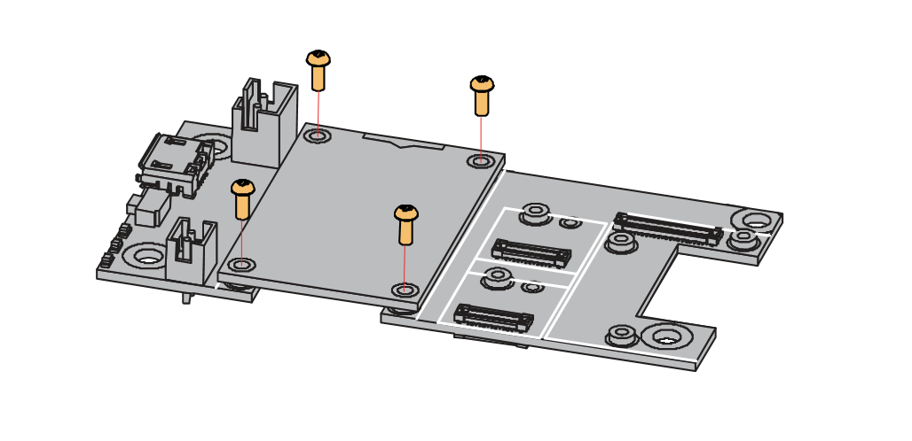
- First, remove the screws.
 Figure 1: Removing screws from the WisBlock module
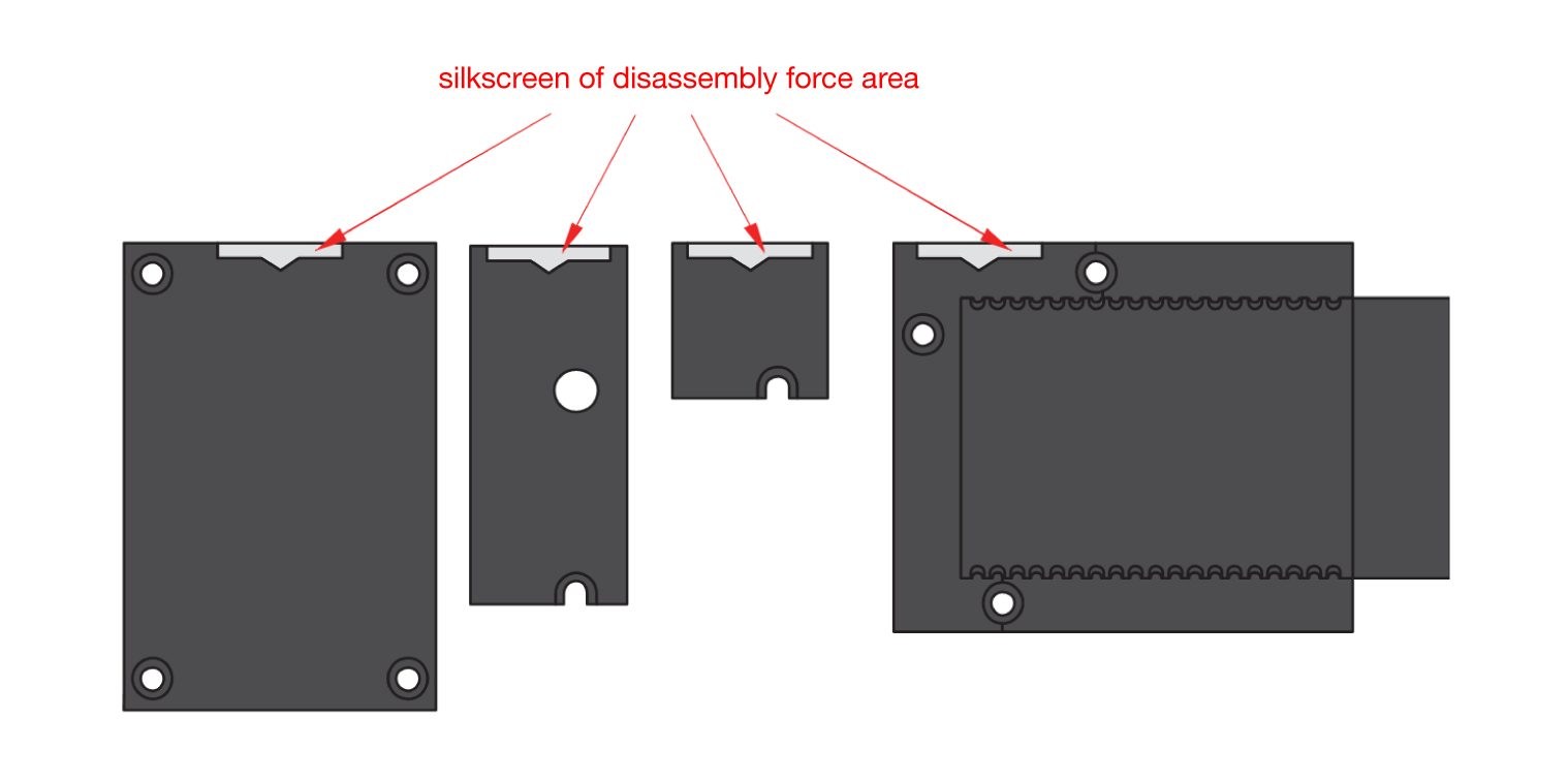
- Once the screws are removed, check the silkscreen of the module to find the correct location where force can be applied.
 Figure 1: Detaching silkscreen on the WisBlock module
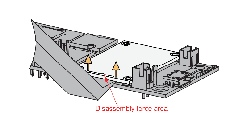
- Apply force to the module at the position of the connector, as shown in Figure 5, to detach the module from the baseboard.
 Figure 1: Applying even forces on the proper location of a WisBlock module
GPS Antenna
Another important component of RAK1910 is the GPS antenna. You need to ensure that it is properly connected to have a good GPS signal.
 Figure 1: GPS antenna
If you will connect other modules to the remaining WisBlock Base slots, check the WisBlock Pin Mapper tool for possible conflicts. RAK1910 uses UART communication lines and it can cause possible conflicts, especially to some IO modules.
After setting up, you can now connect the battery and USB cable to start programming your WisBlock Core.
- Batteries can cause harm if not handled properly.
- Only 3.7-4.2 V Rechargeable LiPo batteries are supported. It is highly recommended not to use other types of batteries with the system unless you know what you are doing.
- If a non-rechargeable battery is used, it has to be unplugged first before connecting the USB cable to the USB port of the board to configure the device. Not doing so might damage the battery or cause a fire.
- Only 5 V solar panels are supported. Do not use 12 V solar panels. It will destroy the charging unit and eventually other electronic parts.
- Make sure the battery wires match the polarity on the WisBlock Base board. Not all batteries have the same wiring.
Software Configuration and Example
The GPS module starts up by default at 9600 bps. This UART speed can be increased using the library functions that have been designed for controlling and managing the module.
The GPS receiver has two operational modes: the NMEA (National Marine Electronics Association) Mode and a Binary Mode called the UBX Protocol. The NMEA mode uses statements from this standard to obtain location, time, and date. The UBX Protocol is based on structured frames to establish communication between the microcontroller and the GPS receiver. The UBX Protocol allows you to configure your GPS module, request information about the position, navigation, even the hardware.
Here are the main NMEA statements that the RAK1910 GPS receiver supports. Others may be sent, automatically or upon request.
- NMEA GGA: Provides location data and an indicator of data accuracy.
- NMEA GSA: Provides the status of the satellites the GPS receiver has been connected to.
- NMEA GSV: Provides information about the satellites the GPS receiver has been connected to.
- NMEA RMC: Provides information about the date, time, location, and speed.
- NMEA VTG: Provides information about the speed and course of the GPS receiver.
- NMEA GLL: Provides information about the location of the GPS receiver.
The most important NMEA statements are the GGA (Global positioning system fix data) statement, which provides time and position, together with GPS fixing-related data (number of satellites in use, and the resulting HDOP, age of differential data if in use, etc.). The RMC (Recommended Minimum data) statement, which provides location, course, speed, and date/time; and the GSA (GNSS DOP and Active Satellites) statement, which provides information about the GPS receiver operating mode, satellites used for navigation, and DOP (dilution of precision) values.
- The included active GPS antenna must be securely attached to the iPEX antenna connector on the board. This is very important, otherwise the module will not work.
- You need to set up the device outdoors. It will take some time for the device to get stable satellite connectivity. If you will configure it indoors, it will probably not work, unless you are next to a window, and have a clear line of sight to the sky.
Initial Test of the RAK1910 WisBlock Module
-
Install the RAKwireless Arduino BSP for WisBlock by using the
package_rakwireless_index.jsonboard installation package. The WisBlock Core should now be available on the Arduino IDE. -
You need to select the WisBlock Core you have.
RAK4631 WisBlock Core
 Figure 1: Selecting RAK4631 as WisBlock Core
RAK11200 WisBlock Core
 Figure 1: Selecting RAK11200 as WisBlock Core
RAK11310 WisBlock Core
 Figure 1: Selecting RAK11310 as WisBlock Core
- Next, copy the following sample code into your Arduino IDE:
Click to view the example
/**
   @file RAK1910_GPS_UBLOX7.ino
   @author rakwireless.com
   @brief get and parse gps data
   @version 0.1
   @date 2020-12-28
   @copyright Copyright (c) 2020
**/

#include <Wire.h>

#include <TinyGPS.h>    //http://librarymanager/All#TinyGPS

TinyGPS gps;
String tmp_data = "";
int direction_S_N = 0;  //0--S, 1--N
int direction_E_W = 0;  //0--E, 1--W

void setup()
{
  // Initialize Serial for debug output
  time_t timeout = millis();
  Serial.begin(115200);
  while (!Serial)
  {
    if ((millis() - timeout) < 5000)
    {
      delay(100);
    }
    else
    {
      break;
    }
  }


  //gps init
  pinMode(WB_IO2, OUTPUT);
  digitalWrite(WB_IO2, 0);
  delay(1000);
  digitalWrite(WB_IO2, 1);
  delay(1000);

  Serial1.begin(9600);
  while (!Serial1)
    ;
  Serial.println("GPS uart init ok!");
}

void direction_parse(String tmp)
{
    if (tmp.indexOf(",E,") != -1)
    {
        direction_E_W = 0;
    }
    else
    {
        direction_E_W = 1;
    }

    if (tmp.indexOf(",S,") != -1)
    {
        direction_S_N = 0;
    }
    else
    {
        direction_S_N = 1;
    }
}

void loop()
{
  bool newData = false;
  unsigned long chars;
  unsigned short sentences, failed;

  // For one second we parse GPS data and report some key values
  for (unsigned long start = millis(); millis() - start < 1000;)
  {
    while (Serial1.available())
    {
      char c = Serial1.read();
      tmp_data += c;
      if (gps.encode(c))
        newData = true;
    }
  }
  direction_parse(tmp_data);
  tmp_data = "";

  if (newData)
  {
    float flat, flon;
    unsigned long age;
    gps.f_get_position(&flat, &flon, &age);
    if(direction_S_N == 0)
    {
      Serial.print("(S):");
    }
    else
    {
      Serial.print("(N):");
    }
    Serial.print("LAT=");
    Serial.print(flat == TinyGPS::GPS_INVALID_F_ANGLE ? 0.0 : flat, 6);
    if(direction_E_W == 0)
    {
      Serial.print(" (E):");
    }
    else
    {
      Serial.print(" (W):");
    }
    Serial.print("LON=");
    Serial.print(flon == TinyGPS::GPS_INVALID_F_ANGLE ? 0.0 : flon, 6);
    Serial.print(" SAT=");
    Serial.print(gps.satellites() == TinyGPS::GPS_INVALID_SATELLITES ? 0 : gps.satellites());
    Serial.print(" PREC=");
    Serial.print(gps.hdop() == TinyGPS::GPS_INVALID_HDOP ? 0 : gps.hdop());
  }

  gps.stats(&chars, &sentences, &failed);
  Serial.print(" CHARS=");
  Serial.print(chars);
  Serial.print(" SENTENCES=");
  Serial.print(sentences);
  Serial.print(" CSUM ERR=");
  Serial.println(failed);
  if (chars == 0)
    Serial.println("** No characters received from GPS: check wiring **");
}
If you experience any error in compiling the example sketch, check the updated code for your WisBlock Core Module that can be found on the RAK1910 WisBlock Example Code Repository and this sample code in Github will work on all WisBlock Core.
- Once the example code is open, install the TinyGPS library by clicking the highlighted link, as shown in Figure 10.
 Figure 1: Installing TinyGPS
- After the successful installation of the library, you can now select the right port and upload the code, as shown in Figure 11.
If you are using the RAK11200 as your WisBlock Core, the RAK11200 requires the Boot0 pin to be configured properly first before uploading. If not done properly, uploading the source code to RAK11200 will fail. Check the full details on the RAK11200 Quick Start Guide.
 Figure 1: Opening RAK1910 example for RAK4631 WisBlock Core
- When you successfully upload the example sketch, open the Serial Monitor of the Arduino IDE to see the logs. The GPS will try to get a signal fix from satellites, and this will vary depending on your location and whether you have a direct line of sight to the sky. It can take a few seconds to a few minutes. If you see the logs, as shown in Figure 12, your RAK1910 is properly communicating to the WisBlock core.
 Figure 1: Scanning GPS signal logs
- If everything is successful, you should now see the GPS coordinates on the Serial Monitor of the Arduino IDE, as shown in Figure 13.
It is possible that you will not see the same serial logs in Figure 12 as soon as you power up the unit, since the GPS module will still update its almanac and ephemeris data. The time it takes is called TTFF or Time to first fix.
It can range to more than 2 minutes depending on how good the satellite signals are in your location. After the almanac and ephemeris are updated, TTFF should be shorter, and getting a GPS signal fix will be faster.
 Figure 1: Scanning GPS signal logs
RAK1910 LoRaWAN GPS Tracker
For WisBlock Core RAK4630, it has an example for LoRaWAN GPS Tracker. For WisBlock Core RAK11310, it has an example for LoRaWAN GPS Tracker.
The following example codes are compatible to LoRaWAN GPS Tracker Kits:
You also need to have a RAK1904 (Accelerometer Module) for this example since it will trigger the transmission of LoRaWAN packets. You can connect the RAK1904 on SLOT C or SLOT D of the WisBlock Base, which are on the other side of the board.
After preparing the hardware, you can now open the example sketch, as shown in Figure 25.
 Figure 1: LoRaWAN GPS Tracker example
After successful compilation, you should be able to see a successful join request if you are within range of a compatible gateway and with the right LoRaWAN joining parameters. More information about the LoRaWAN configuration can be found on Quick Start Guide of RAK4631.
After uploading the code, the device will not automatically send GPS coordinates but only when a specific orientation is achieved. The following part of the code will trigger the sending of LoRaWAN packets.
data = "";
if (abs(x - z) < 400)
If the absolute value of the difference between the X and Z axis is less than 400, the LoRaWAN packets will be transmitted to the LoRaWAN network server. Physically, if you are using a WisBlock Base board, you can trigger this condition by positioning the WisBlock upright with the USB connector either at the top or at the bottom. You can create your own conditions too when to transmit the LoRaWAN Payload.
There will be no LoRaWAN transmission if there is no GPS signal found or if the accelerometer is not in the right orientation.
It can take a few seconds or minutes to get a good fix depending on your location and situation. If all are successful after waiting for the GPS signal, you should now see this on the serial monitor/terminal.
The packet should also arrive at the LoRaWAN network server you use. The values you see will not make sense and don't look like GPS coordinates. It is normal because the payload hasn't been decoded yet.
If you are using Chirpstack, you will see the packet as shown in Figure 28.
 Figure 1: Chirpstack LoRaWAN payload
If you are using The Things Stack (TTN V3), you will see the packet as shown in Figure 29.
 Figure 1: TTS LoRaWAN payload
Payload Decoding of LoRaWAN GPS Tracker
Data format
Data sent to LoRaWAN server of the example code has the following format:
- Buffer[0] - 0x09 (Header indicator that the data is the GPS coordinate).
- Buffer[1-4] - Latitude value in integer. To get the actual latitude value in float, this integer must be divided by 10000. This can be done on the payload decoder side.
- Buffer[5] - It can be 'S' or 'N' which pertains to geographical location.
- Buffer[6-9] - Latitude value in integer. To get the actual latitude value in float, this integer must be divided by 10000. This can be done on the payload decoder side.
- Buffer[10] - It can be 'E' or 'W' which pertains to geographical location.
Chirpstack Decoder
Here is the payload decoder that you can use for Chirpstack.
function Decode(fport, bytes)
{
  var longitude_int, latitude_int;
  var decoded = {"latitude":"","longitude":""};

  if (fport === 2) {
    if(bytes[0]==9) // check if the header byte is 9.
    {
      latitude_int = (bytes[1] << 24) | (bytes[2] << 16) | (bytes[3] << 8) | (bytes[4]);
      decoded.latitude = latitude_int / 100000;
      longitude_int = (bytes[6] << 24) | (bytes[7] << 16) | (bytes[8] << 8) | (bytes[9]);
      decoded.longitude = longitude_int / 100000;
      return decoded;
    }
  }
}
If you got the right payload, the decoded payload should look like in Figure 30.
 Figure 1: Chirpstack decoded GPS payload
TTS Decoder
Here is the payload decoder that you can use for TTS.
function Decoder(bytes, port)
{
  var longitude_int, latitude_int;
  var decoded = {};

  if (port === 2) {
    if(bytes[0]==9) // check if the header byte is 9.
    {
      latitude_int = (bytes[1] << 24) | (bytes[2] << 16) | (bytes[3] << 8) | (bytes[4]);
      decoded.latitude = latitude_int / 100000;
      longitude_int = (bytes[6] << 24) | (bytes[7] << 16) | (bytes[8] << 8) | (bytes[9]);
      decoded.longitude = longitude_int / 100000;
      return decoded;
    }
  }
}
After modifying the decoder in TTS, you can now see the GPS coordinates value as latitude and longitude.
 Figure 1: TTS Decoded GPS payload
Timing
In this LoRaWAN GPS example, an accelerometer is checked every 10 seconds. On actual LoRaWAN deployments, the delay should be much higher in order to follow the regulations stated on the LoRaWAN Regional Parameters specifications.
If there is no GPS coordinate transmission even if you are sure that the accelerometer is already in the right trigger orientation if (abs(x - z) < 400), then you need to check the RAK1910 GPS module if you can get GPS signal. Perform the initial RAK1910 quick test.
